Runtime name format explained for a FC Storage Device

Runtime Name

The name of the first path to the device. The runtime name is created by the host. The name is not a reliable identifier for the device, and is not persistent.
The runtime name has the following format:

vmhba#:C#:T#:L#

  • vmhba# is the name of the storage adapter. The name refers to the physical adapter on the host, not to the SCSI controller used by the virtual machines.
  • C# is the storage channel number.
  • T# is the target number. Target numbering is decided by the host and might change if there is a change in the mappings of targets visible to the host. Targets that are shared by different hosts might not have the same target number.
  • L# is the LUN number that shows the position of the LUN within the target. The LUN number is provided by the storage system. If a target has only one LUN, the LUN number is always zero (0).

For example, vmhba1:C0:T3:L1 represents LUN1 on target 3 accessed through the storage adapter vmhba1 and channel 0.

RDM’s – Physical and Virtual Compatibility Mode


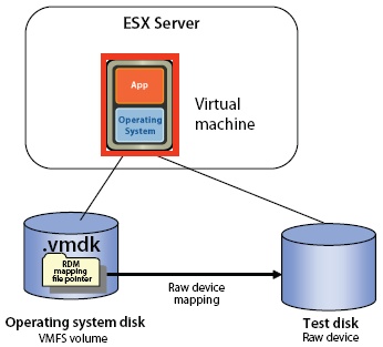
An RDM can be thought of as a symbolic link from a VMFS volume to a raw LUN. The mapping makes LUNs appear as files in a VMFS volume.

The mapping file, not the raw LUN, is referenced in the virtual machine configuration.
When a LUN is opened for access, the mapping file is read to obtain the reference to the raw LUN. Thereafter, reads and writes go directly to the raw LUN rather than going through the mapping file.

There are two types of RDMs: Virtual compatibility mode RDMs and physical compatibility mode RDMs.

Physical Mode RDM’s Uses

  • Useful if you are using SAN-aware applications in the virtual machine
  • Useful to run SCSI target based software
  • Physical mode for the RDM specifies minimal SCSI virtualization of the mapped device, allowing the greatest flexibility for SAN management software. In physical mode, the VMkernel passes all SCSI commands to the device, with one exception: the REPORT LUNs command is virtualized, so that the VMkernel can isolate the LUN for the owning virtual machine. Otherwise, all physical characteristics of the underlying hardware are exposed. Physical mode is useful to run SAN management agents or other SCSI target based software in the virtual machine.

Physical mode RDMs Limitations

  • No VMware snapshots
  • No VCB support, because VCB requires VMware snapshots
  • No cloning VMs that use physical mode RDMs
  • No converting VMs that use physical mode RDMs into templates
  • No migrating VMs with physical mode RDMs if the migration involves copying the disk
  • No VMotion with physical mode RDMs

Virtual mode RDM’s Advantage

  • Advanced file locking for data protection
  • VMware Snapshots
  • Allows for cloning
  • Redo logs for streamlining development processes
  • More portable across storage
    hardware, presenting the same behavior as a virtual disk file

Predictive and Adaptive Schemes for placing VMFS Datastores

Predictive

The Predictive Scheme utilizes several LUNs with different storage characteristics

  • Create several Datastores (VMFS or NFS) with different storage characteristics and label each datastore according to its characteristics
  • Locate each application in the appropriate RAID for its requirements by measuring the requirements in advance
  • Run the applications and see whether VM performance is acceptable or monitor HBA queues as they approach the queue full threshold
  • Use RDM’s sparingly and as needed

Adaptive

The Adaptive Scheme utilizes a small number of large LUNs

  • Create a standardised Datastore building bloc model (VMFS or NFS)
  • Place virtual disks on the Datastore
  • Run the applications and see whether disk performance is acceptable (On a VMFS Datastore, monitor the HBA queues as they approach the queue full threshold
  • If performance is acceptable, you can place additional virtual disks on the Datastore.If it isn’t Storage vMotion the disks on to a new Datastore
  • Use RDM’s sparingly

Private VLAN’s

Private VLANs are used to solve VLAN ID limitations and waste of IP addresses for certain network setups.

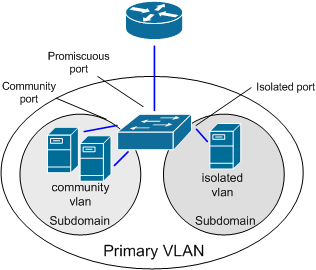
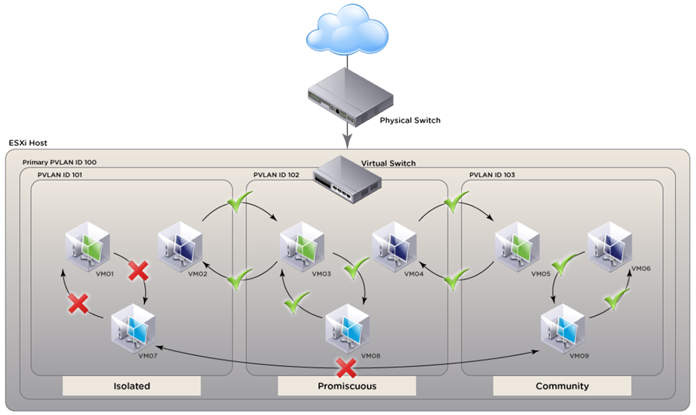
PVLANs segregate VLANs even further than normal, they are basically VLANs inside of VLANs. The ports share a subnet, but can be prevented from communicating. They use different port types:

Promiscuous ports – These will be the “open ports” of the PVLANs, they can communicate with all other ports.
Community ports – These ports can communicate with other community ports and promiscuous ports.
Isolated ports – These can ONLY communicate with promiscuous ports.

There are different uses for PVLANs. They are used by service providers to allow customer security while sharing a single subnet. Another use could be for DMZ hosts in an enterprise environment. If one host is compromised its ability to inflict damage to the other hosts will be severely limited.

How vSphere implements private VLANs

  • vSphere does not encapsulate traffic in private VLANs. In other words, no secondary private VLAN is encapsulated in a primary private VLAN packet
  • Traffic between virtual machines on the same private VLAN but on different hosts will need to move through the physical switch. The physical switch must be private VLAN aware and configured appropriately so traffic can reach its destination

Configuring and Assigning a Primary VLAN and Secondary VLAN

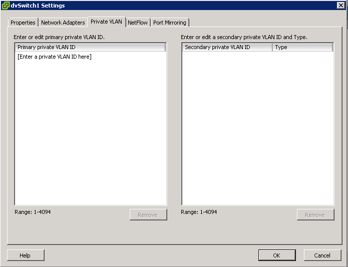
  • Right click the Distributed switch and select Edit Settings
  • Select the Private VLAN tab

pvlan

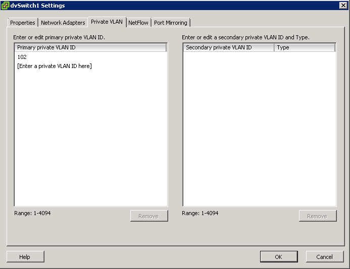
  • On the Primary tab, add the VLAN that is used outside the PVLAN domain. Enter a private VLAN
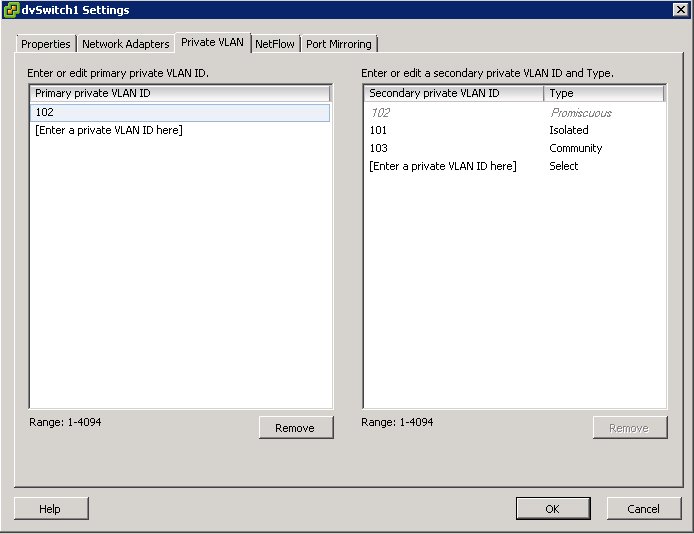
  • Note: There can be only one Promiscuous PVLAN and is created automatically for you

vlan6

  • For each new Secondary Private VLAN, click Enter a private VLAN ID here under Secondary Private VLAN ID and enter the number of the Secondary Private VLAN
  • Click anywhere in the dialog box, select the secondary private VLAN that you added and select Isolated or Community for the port type

pvlan4

Diagram of Configuration courtesy of VMware

pvlan2

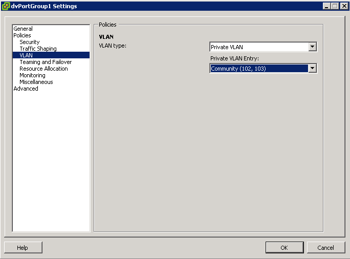
After the primary and secondary private VLANs are associated for the VDS, use the association to configure the VLAN policy for the distributed port group

  • Right click the Distributed Port Group in the networking inventory view and select Edit Settings
  • Select policies
  • Select the VLAN type to use and click OK

vlan5

Useful KB Article

Private VLAN (PVLAN) on vNetwork Distributed Switch – Concept Overview KB

Troubleshooting PVLANs

  1. Ensure that VLANs and PVLANs are properly configured on the physical switch.
  2. Promiscuous (Primary) PVLAN can communicate with all interfaces on the VLAN. There can only be one Primary PVLAN per VLAN.
  3. VMs in an Isolated (Secondary) PVLAN can only communicate with the Promiscuous port, not with other VMs in the Isolated PVLAN. To prevent communication between two VMs using PVLANs, place them in the Isolated PVLAN.
  4. VMs in the same Community (Secondary) PVLAN can communicate with each other and the Promiscuous port. There can be multiple Community PVLANs in the same PVLAN. Ensure that VMs are members of the same Community PVLAN if communication is required between them.
  5. Ensure that the correct port groups have been configured for each PVLAN.
  6. Verify that the VM(s) in question are configured to use the appropriate port group.

vSphere 5 Documentation Centre

Intended Audience

This information is intended for those who need to familiarize themselves with the components and capabilities of VMware vSphere. This information is for experienced Windows or Linux system administrators who are familiar with virtual machine technology and datacenter operations.

http://pubs.vmware.com/vsphere-50/index.jsp

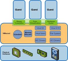
How is the VMKernel secured?

Memory Hardening – The ESX/ESXi kernel, user-mode applications, and executable components such as drivers and libraries are located at random, non-predictable memory addresses. Combined with the nonexecutable memory protections made available by microprocessors, this provides protection that makes it difficult for malicious code to use memory exploits to take advantage of vulnerabilities.
Kernel Module Integrity – Digital signing ensures the integrity and authenticity of modules, drivers and applications as they are loaded by the VMkernel. Module signing allows ESXi to identify the providers of modules, drivers, or applications and whether they are VMware-certified. Trusted Platform Module (ESXi ONLY and BIOS enabled) – This module is a hardware element that represents the core of trust for a hardware platform and enables attestation of the boot process, as well as cryptographic key storage and protection. Each time ESXi boots, TPM measures the VMkernel with which ESXi booted in one of its Platform Configuration Registers (PCRs). TPM measurements are propagated to vCenter Server when the host is added to the vCenter Server system

Useful VCP 5 Exam Link

http://www.aiotestking.com/vmware/category/vmware-certified-professional-on-vsphere5/

Simon Long’s VCP 5 practice exams

The VMware VCP 5 mock exam

Ingress and Egress Traffic Shaping

The terms Ingress source and Egress source are with respect to the VDS.

For example:

Ingress – When you want to monitor the traffic that is going out of a virtual machine towards the VDS, it is called Ingress Source traffic. The traffic seeks ingress to the VDS and hence the source is called Ingress.

Egress – When you want to monitor the traffic that is going out of the VDS towards the VM, it is called egress

Traffic Shaping concepts:

Average Bandwidth: Kbits/sec

Target traffic rate cap that the switch tries to enforce. Every time a client uses less than the defined Average Bandwidth, credit builds up.

Peak Bandwidth: Kbits/sec

Extra bandwidth available, above the Average Bandwidth, for a short burst. The availability of the burst depends on credit accumulated so far.

Burst Size: Kbytes

Amount of traffic that can be transmitted or received at Peak speed (Combining Peak Bandwidth and Burst Size you can calculate the maximum allowed time for the burst

Traffic Shaping on VSS and VDS

VSS

Traffic Shaping can be applied to a vNetwork Standard Switch port group or the entire vSwitch for outbound traffic only

VDS

Traffic Shaping can be applied to a vNetwork Distributed Switch dvPort or the entire dvPort Group for inbound and outbound traffic

IOPs

When planning for storage to your VMware architecture, it is easy to focus on the storage capacity dimension rather than focusing on availability and performance

Capacity is generally not the limit for proper storage configurations. Capacity reducing techniques such as deduplication, thin provisioning and compression means you can now use disk capacity far more efficiently than before.

So what are IOP’s?

IOPS (Input/Output Operations Per Second, pronounced eye-ops) are a common performance measurement used to benchmark computer storage devices like hard disk drives (HDD), solid state drives (SSD), and storage area networks (SAN). As with any benchmark, IOPS numbers published by storage device manufacturers do not guarantee real-world application performance

IOPS can be measured with applications, such as Iometer (originally developed by Intel), as well as IOzone and FIO and is primarily used with servers to find the best storage configuration.

The specific number of IOPS possible in any system configuration will vary greatly, depending upon the variables the tester enters into the program, including the balance of read and write operations, the mix of sequential and random access patterns, the number of worker threads and queue depth, as well as the data block sizes.There are other factors which can also affect the IOPS results including the system setup, storage drivers, OS background operations, etc. Also, when testing SSDs in particular, there are preconditioning considerations that must be taken into account.

Computer IOP’s

Virtual Desktops use 5-20 IOP’s

Light Servers use 50-100 IOP’s

Heavy Servers – Require independent measurement for true accuracy

Storage Drive IOP’s

Enterprise Flash Drives = 1000 IOP’s pr drive

FC 15K RPM SAS Drives = 180 IOP’s per drive

FC 10K RPM SAS Drives = 120 IOP’s per drive

10K RPM SATA Drives = 125-150 IOP’s per drive

7K RPM SATA Drives = 75-100 IOP’s per drive

5.4K RPM SATA Drives = 80 IOPS per drive

Performance Characteristics

The most common performance characteristics measured are sequential and random operations.

  • Sequential operations access locations on the storage device in a contiguous manner and are generally associated with large data transfer sizes, e.g. 128 KB.
  • Random operations access locations on the storage device in a non-contiguous manner and are generally associated with small data transfer sizes, e.g. 4 KB.

Useful Performance Link

http://kb.vmware.com/selfservice/microsites/search.do?language=en_US&cmd=displayKC&externalId=1031773

Network Time Sync for VMware ESXi Hosts

In a virtual infrastructure, network time synchronization is critical to keep servers on the same schedule as the services they rely on. For VMware ESXi hosts, you can implement Network Time Protocol (NTP) synchronization using the vSphere Client.

More on VMware networking

There are many reasons you should synchronize time for ESXi hosts. If they are integrated with Active Directory, for instance, you need time to be properly synchronized. You also need the time to be consistent when creating and resuming snapshots, because snapshots take point-in-time images of the server state. Luckily, setting up network time synchronization with the vSphere Client is pretty easy.

VMware network time synchronization: A walkthrough

To configure NTP synchronization, select the host, and on the Configuration tab, select Time Configuration under Software. You’ll now see the existing time synchronization status on that host. Next, click Properties. This selection shows the Time Configuration screen, where you can see the current time on the host. Make sure it’s not too different from the actual time, because a host that’s more than 1,000 seconds is considered “insane” and won’t synchronize.

After you set the local time on the host, select NTP Client Enabled. This activates NTP time synchronization for your host. Reboot the server, then go to Options to make sure NTP has been enabled. This gives you access to the NTP Startup Policy, where you should select “Start and stop with host.”

You’re not done with network time synchronization yet, though. Now, you need to choose NTP servers that your VMware ESXi hosts should synchronize with. Click NTP Settings and you’ll see the current list of NTP servers. By default, it’s empty. Click Add to add the name or address of the NTP server you’d like to use. The interface prompts you for an address, but you can enter a name that can be resolved by DNS as well.

If you’re not sure which NTP server to use for VMware network time synchronization, the Internet NTP servers in pool.ntp.org work well. You only need to choose one server from this group to add to the NTP servers list. If you want to synchronize with an internal or proprietary NTP server, however, you should specify at least two NTP servers.

At this point, make sure the option to restart the NTP server is selected. Click OK three times to save and apply your changes. From the Configuration screen on your ESXi host, you should now see that the NTP Client is running, and it will also show the list of current NTP servers your host is using.

With your ESXi hosts synchronized to the correct time, all the services and events that depend on time will function properly. More importantly, you won’t waste any more time because of misconfigured network time