SQL Database Tables getting too big in VMware

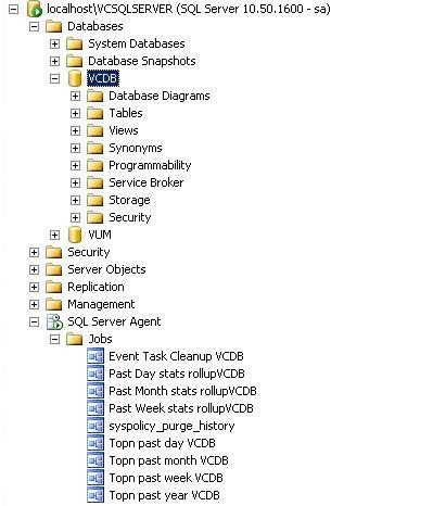
Checking vCenter DB Table sizes

Sometimes you can experience issues with the vCenter Database getting too large. If you want to check the table sizes to confirm this, please do the following.

  • Open SQL Management Studio
  • Select vCenter DB name
  • Execute the following query to get Table sizes

Create Table #Temp(Name sysname, rows int, reserved varchar(100), data varchar(100), index_size varchar(100), unused varchar(100))

exec sp_msforeachtable ‘Insert Into #Temp Exec sp_spaceused ”?”, ”true”’

Select * From #Temp

Drop Table #Temp

Purge Scripts

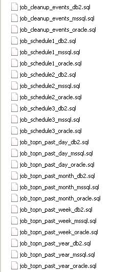
There are a set of purge scripts where you can set how much historical data you keep and it will remove everything else from the DB.

Take a look at this KB, it runs through the process and has a link to the scripts:

http://kb.vmware.com/kb/1025914

One thing I will say is that the scripts can take a long time to run, If the size of your DB is quite large, it could take quite a while to complete. I would kick it off and let it run over the weekend if it hasn’t completed by the end of the day. Also the scripts are perfectly safe but I would take a backup of the DB before doing anything just for peace of mind

DB Maintenance

You should run a shrink on the DB to remove empty space and a regular backup is a good idea as MS SQL uses this to do maintenance on the DB. If you check out the Microsoft documentation for your version of MS SQL there should be detail and recommendation for setting that up

Useful Links

Defragmenting VirtualCenter performance data indexes on a Microsoft SQL database:

http://kb.vmware.com/selfservice/microsites/search.do?language=en_US&cmd=displayKC&externalId=1003990

Unable to get an exclusive access to the vCenter Server repository:

http://kb.vmware.com/selfservice/microsites/search.do?language=en_US&cmd=displayKC&externalId=1006369

ESXi 4.1 Active Directory Integration

Although day-to-day vSphere management operations are usually done on vCenter Server logged in through the vSphere Client, there are instances when users must work with ESXi directly, such as with configuration backup and log file access.  Then there are monitoring solutions, which sometimes require direct access to the ESXi host; these would typically be configured to use service accounts. Prior to ESXi 4.1, you could only create local users, which each had separate locally-stored passwords per host.  Since this is cumbersome and doesn’t scale, VMware decided to address this in the vSphere 4.1 release.

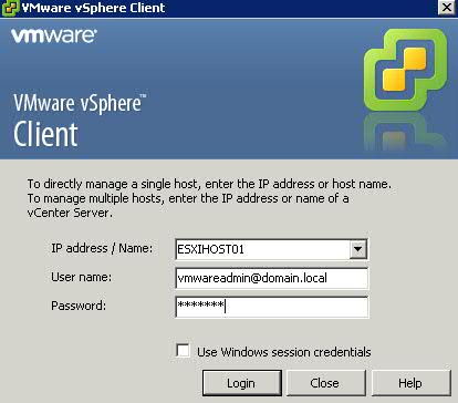
With ESXi 4.1, you can configure the host to join an Active Directory domain, and any user trying to access the host will automatically be authenticated against the centralized user directory.   Any time you are asked to provide credentials (e.g., logging in directly to the ESXi host using vSphere Client, or running a vCLI command or script), you can enter the username and password of a user in the domain to which the host is joined. The big advantage of this is that you can now continue to manage user accounts using Active Directory, which is significantly easier and more secure than trying to manage accounts independently on a per-host basis.

You can still have local users defined and managed on a host-by-host basis and configured using the vSphere client, vCLI or PowerCLI. This can be used in place of, or in addition to, the Active Directory integration.  I’m not sure if there is really a good reason to do this if the host is already joined to an AD domain, but this capability is available.

If the host is integrated with Active Directory, local roles can also be granted to Active Directory users and groups. For example, an Active Directory group can be created to include users who should have an administrator role on a subset of ESXi servers. On those servers, the administrator role can be granted to that Active Directory group; for all other servers, those users would not have an administrator role. ESXi 4.1 also automatically grants administrator access to the Active Directory group named “ESX Admins,” which allows the creation of a global administrators group.  (If you want to override this behavior, simply configure the roles on the ESXi host to give the “No Access” role to the “ESX Admins” group — this will override the default behavior).

Instructions

  • Select a Host > Click Configuration > Click Authentication Services


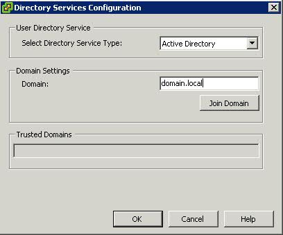
  • Click Properties and choose Active Directory from thr Drop Down Option and then type in the domain. In this example, it is domain.local

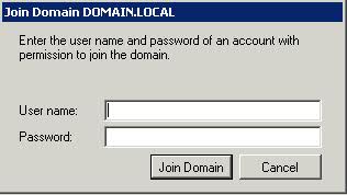
  • Click Join Domain and Enter  a username and password which has authority to join machines to the domain

  • You have now joined the host to the AD Domain
  • Log into Active Directory and you now need to create a new Global Security Group called ESX Admins. This is the default security group that the ESX host is going to be looking for
  • Right Click Group and Add Members
  • Now you can test this by opening up the vSphere client and test this

  • If you then click on the Hosts and click on Permissions, you will see the ESX Admins Group Listed
  • You can then add other Permissions by right clicking in the screen and selecting Add Permission
  • Choose your AD user and then select the VMware Role you want this AD user to have

Memory Over Allocation for VM’s – What Happens?

ESX employs a share-based allocation algorithm to achieve efficient memory utilization for all virtual machines and to guarantee memory to those virtual machines which need it most

ESX provides three configurable parameters to control the host memory allocation for a virtual machine

  • Shares
  • Reservation
  • Limit

Limit is the upper bound of the amount of host physical memory allocated for a virtual machine. By default, limit is set to unlimited, which means a virtual machine’s maximum allocated host physical memory is its specified virtual machine memory size

Reservation is a guaranteed lower bound on the amount of host physical memory the host reserves for a virtual machine even when host memory is overcommitted.

Memory Shares entitle a virtual machine to a fraction of available host physical memory, based on a proportional-share allocation policy. For example, a virtual machine with twice as many shares as another is generally entitled to consume twice as much memory, subject to its limit and reservation constraints.

Periodically, ESX computes a memory allocation target for each virtual machine based on its share-based entitlement, its estimated working set size, and its limit and reservation. Here, a virtual machine’s working set size is defined as the amount of guest physical memory that is actively being used. When host memory is undercommitted, a virtual machine’s memory allocation target is the virtual machine’s consumed host physical memory size with headroom

VMware Resource Management (Memory)

VMware® ESX(i)™ is a hypervisor designed to efficiently manage hardware resources including CPU, memory, storage, and network among multiple, concurrent virtual machines.

Memory Overcommittment

The concept of memory overcommitment is fairly simple: host memory is overcommitted when the total amount of guest physical memory of the running virtual machines is larger than the amount of actual host memory. ESX supports memory overcommitment from the very first version, due to two important benefits it provides:

  • Higher memory utilization: With memory overcommitment, ESX ensures that host memory is consumed by active guest memory as much as possible. Typically, some virtual machines may be lightly loaded compared to others. Their memory may be used infrequently, so for much of the time their memory will sit idle. Memory overcommitment allows the hypervisor to use memory reclamation techniques to take the inactive or unused host physical memory away from the idle virtual machines and give it to other virtual machines that will actively use it.
  • Higher consolidation ratio: With memory overcommitment, each virtual machine has a smaller footprint in host memory usage, making it possible to fit more virtual machines on the host while still achieving good performance for all virtual machines. For example, as shown in Figure 3, you can enable a host with 4G host physical memory to run three virtual machines with 2G guest physical memory each. Without memory overcommitment, only one virtual machine can be run because the hypervisor cannot reserve host memory for more than one virtual machine, considering that each virtual machine has overhead memory.

ESX uses several innovative techniques to reclaim virtual machine memory, which are:

  • Transparent page sharing (TPS)
  • Reclaims memory by removing redundant pages with identical content
  • Ballooning
  • Reclaims memory by artificially increasing the memory pressure inside the guest
  • Hypervisor/Host swapping
  • Reclaims memory by having ESX directly swap out the virtual machine’s memory
  • Memory compression
  • Reclaims memory by compressing the pages that need to be swapped out

Transparent Page Sharing

When multiple virtual machines are running, some of them may have identical sets of memory content. This presents opportunities for sharing memory across virtual machines (as well as sharing within a single virtual machine). For example, several virtual machines may be running the same guest operating system, have the same applications, or contain the same user data. With page sharing, the hypervisor can reclaim the redundant copies and keep only one copy, which is shared by multiple virtual machines in the host physical memory. As a result, the total virtual machine host memory consumption is reduced and a higher level of memory overcommitment is possible.
In ESX, the redundant page copies are identified by their contents. This means that pages with identical content can be shared regardless of when, where, and how those contents are generated. ESX scans the content of guest physical memory for sharing opportunities. Instead of comparing each byte of a candidate guest physical page to other pages, an action that is prohibitively expensive, ESX uses hashing to identify potentially identical pages.
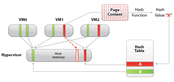
A hash value is generated based on the candidate guest physical page’s content. The hash value is then used as a key to look up a global hash table, in which each entry records a hash value and the physical page number of a shared page. If the hash value of the candidate guest physical page matches an existing entry, a full comparison of the page contents is performed to exclude a false match. Once the candidate guest physical page’s content is confirmed to match the content of an existing shared host physical page, the guest physical to host physical mapping of the candidate guest physical page is changed to the shared host physical page, and the redundant host memory copy (the page pointed to by the dashed arrow in the Figure above) is reclaimed. This remapping is invisible to the virtual machine and inaccessible to the guest operating system. Because of this invisibility, sensitive information cannot be leaked from one virtual machine to another.

A standard copy-on-write (CoW) technique is used to handle writes to the shared host physical pages. Any attempt to write to the shared pages will generate a minor page fault. In the page fault handler, the hypervisor will transparently create a private copy of the page for the virtual machine and remap the affected guest physical page to this private copy. In this way, virtual machines can safely modify the shared pages without disrupting other virtual machines sharing that memory. Note that writing to a shared page does incur overhead compared to writing to non-shared pages due to the extra work performed in the page fault handler.
In VMware ESX, the hypervisor scans the guest physical pages randomly with a base scan rate specified by Mem.ShareScanTime, which specifies the desired time to scan the virtual machine’s entire guest memory. The maximum number of scanned pages per second in the host and the maximum number of per-virtual machine scanned pages, (that is, Mem.ShareScanGHz and Mem.ShareRateMax respectively) can also be specified in ESX advanced settings. An example is shown in the Figure below

The default values of these three parameters are carefully chosen to provide sufficient sharing opportunities while keeping the CPU overhead negligible. In fact, ESX intelligently adjusts the page scan rate based on the amount of current shared pages. If the virtual machine’s page sharing opportunity seems to be low, the page scan rate will be reduced accordingly and vice versa. This optimization further mitigates the overhead of page sharing.
In hardware-assisted memory virtualization (for example, Intel EPT Hardware Assist and AMD RVI Hardware Assist systems, ESX will automatically back guest physical pages with large host physical pages (2MB contiguous memory region instead of 4KB for regular pages) for better performance due to less TLB misses. In such systems, ESX will not share those large pages because: 1) the probability of finding two large pages having identical contents is low, and 2) the overhead of doing a bit-by-bit comparison for a 2MB page is much larger than for a 4KB page. However, ESX still generates hashes for the 4KB pages within each large page. Since ESX will not swap out large pages, during host swapping, the large page will be broken into small pages so that these pre-generated hashes can be used to share the small pages before they are swapped out. In short, we may not observe any page sharing for hardware-assisted memory virtualization systems until host memory is overcommitted.

Ballooning

Ballooning is a completely different memory reclamation technique compared to transparent page sharing. Before describing the technique, it is helpful to review why the hypervisor needs to reclaim memory from virtual machines. Due to the virtual machine’s isolation, the guest operating system is not aware that it is running inside a virtual machine and is not aware of the states of other virtual machines on the same host. When the hypervisor runs multiple virtual machines and the total amount of the free host memory becomes low, none of the virtual machines will free guest physical memory because the guest operating system cannot detect the host’s memory shortage. Ballooning makes the guest operating system aware of the low memory status of the host.

In ESX, a balloon driver is loaded into the guest operating system as a pseudo-device driver.
VMware Tools must be installed in order to enable ballooning. This is recommended for all workloads. It has no external interfaces to the guest operating system and communicates with the hypervisor through a private channel. The balloon driver polls the hypervisor to obtain a target balloon size. If the hypervisor needs to reclaim virtual machine memory, it sets a proper target balloon size for the balloon driver, making it “inflate” by allocating guest physical pages within the virtual machine. The figure below illustrates the process of the balloon inflating

In the figure below, four guest physical pages are mapped in the host physical memory. Two of the pages are used by the guest application and the other two pages (marked by stars) are in the guest operating system free list. Note that since the hypervisor cannot identify the two pages in the guest free list, it cannot reclaim the host physical pages that are backing them. Assuming the hypervisor needs to reclaim two pages from the virtual machine, it will set the target balloon size to two pages. After obtaining the target balloon size, the balloon driver allocates two guest physical pages inside the virtual machine and pins them, as shown in Figure b. Here, “pinning” is achieved through the guest operating system interface, which ensures that the pinned pages cannot be paged out to disk under any circumstances. Once the memory is allocated, the balloon driver notifies the hypervisor about the page numbers of the pinned guest physical memory so that the hypervisor can reclaim the host physical pages that are backing them. In Figure b, dashed arrows point at these pages. The hypervisor can safely reclaim this host physical memory because neither the balloon driver nor the guest operating system relies on the contents of these pages. This means that no processes in the virtual machine will intentionally access those pages to read/write any values. Thus, the hypervisor does not need to allocate host physical memory to store the page contents. If any of these pages are re-accessed by the virtual machine for some reason, the hypervisor will treat it as a normal virtual machine memory allocation and allocate a new host physical page for the virtual machine. When the hypervisor decides to deflate the balloon—by setting a smaller target balloon size—the balloon driver deallocates the pinned guest physical memory, which releases it for the guest’s applications.
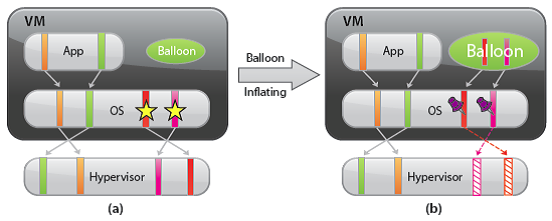

Typically, the hypervisor inflates the virtual machine balloon when it is under memory pressure. By inflating the balloon, a virtual machine consumes less physical memory on the host, but more physical memory inside the guest. As a result, the hypervisor offloads some of its memory overload to the guest operating system while slightly loading the virtual machine. That is, the hypervisor transfers the memory pressure from the host to the virtual machine. Ballooning induces guest memory pressure. In response, the balloon driver allocates and pins guest physical memory. The guest operating system determines if it needs to page out guest physical memory to satisfy the balloon driver’s allocation requests. If the virtual machine has plenty of free guest physical memory, inflating the balloon will induce no paging and will not impact guest performance. In this case, as illustrated in the figure, the balloon driver allocates the free guest physical memory from the guest free list. Hence, guest-level paging is not necessary. However, if the guest is already under memory pressure, the guest operating system decides which guest physical pages to be paged out to the virtual swap device in order to satisfy the balloon driver’s allocation requests. The genius of ballooning is that it allows the guest operating system to intelligently make the hard decision about which pages to be paged out without the hypervisor’s involvement.

Hypervisor/Host Swapping

In the cases where ballooning and transparent page sharing are not sufficient to reclaim memory, ESX employs hypervisor swapping to reclaim memory. At virtual machine startup, the hypervisor creates a separate swap file for the virtual machine. Then, if necessary, the hypervisor can directly swap out guest physical memory to the swap file, which frees host physical memory for other virtual machines.
Besides the limitation on the reclaimed memory size, both page sharing and ballooning take time to reclaim memory. The page-sharing speed depends on the page scan rate and the sharing opportunity. Ballooning speed relies on the guest operating system’s response time for memory allocation.
In contrast, hypervisor swapping is a guaranteed technique to reclaim a specific amount of memory within a specific amount of time. However, hypervisor swapping is used as a last resort to reclaim memory from the virtual machine due to the following limitations on performance:

  • Page selection problems: Under certain circumstances, hypervisor swapping may severely penalize guest performance. This occurs when the hypervisor has no knowledge about which guest physical pages should be swapped out, and the swapping may cause unintended interactions with the native memory management policies in the guest operating system.
  • Double paging problems: Another known issue is the double paging problem. Assuming the hypervisor swaps out a guest physical page, it is possible that the guest operating system pages out the same physical page, if the guest is also under memory pressure. This causes the page to be swapped in from the hypervisor swap device and immediately to be paged out to the virtual machine’s virtual swap device.

Page selection and double-paging problems exist because the information needed to avoid them is not available to the hypervisor.

  • High swap-in latency: Swapping in pages is expensive for a VM. If the hypervisor swaps out a guest page and the guest subsequently accesses that page, the VM will get blocked until the page is swapped in from disk. High swap-in latency, which can be tens of milliseconds, can severely degrade guest performance.

ESX mitigates the impact of interacting with guest operating system memory management by randomly selecting the swapped guest physical pages.

Memory Compression

The idea of memory compression is very straightforward: if the swapped out pages can be compressed and stored in a compression cache located in the main memory, the next access to the page only causes a page decompression which can be an order of magnitude faster than the disk access. With memory compression, only a few uncompressible pages need to be swapped out if the compression cache is not full. This means the number of future synchronous swap-in operations will be reduced. Hence, it may improve application performance significantly when the host is in heavy memory pressure. In ESX 4.1, only the swap candidate pages will be compressed. This means ESX will not proactively compress guest pages when host swapping is not necessary. In other words, memory compression does not affect workload performance when host memory is undercommitted.

Reclaiming Memory through Compression

Figure a,b and c illustrates how memory compression reclaims host memory compared to host swapping. Assuming ESX needs to reclaim two 4KB physical pages from a VM through host swapping, page A and B are the selected pages (Figure a,b,c). With host swapping only, these two pages will be directly swapped to disk and two physical pages are reclaimed (Figure b). However, with memory compression, each swap candidate page will be compressed and stored using 2KB of space in a per-VM compression cache. Note that page compression would be much faster than the normal page swap out operation which involves a disk I/O. Page compression will fail if the compression ratio is less than 50% and the uncompressible pages will be swapped out. As a result, every successful page compression is accounted for reclaiming 2KB of physical memory. As illustrated in Figure c, pages A and B are compressed and stored as half-pages in the compression cache. Although both pages are removed from VM guest memory, the actual reclaimed memory size is one page.

If any of the subsequent memory access misses in the VM guest memory, the compression cache will be checked first using the host physical page number. If the page is found in the compression cache, it will be decompressed and push back to the guest memory. This page is then removed from the compression cache. Otherwise, the memory request is sent to the host swap device and the VM is blocked.

Managing Per-VM Compression Cache

The per-VM compression cache is accounted for by the VM’s guest memory usage, which means ESX will not allocate additional host physical memory to store the compressed pages. The compression cache is transparent to the guest OS. Its size starts with zero when host memory is undercommitted and grows when virtual machine memory starts to be swapped out.
If the compression cache is full, one compressed page must be replaced in order to make room for a new compressed page. An age-based replacement policy is used to choose the target page. The target page will be decompressed and swapped out. ESX will not swap out compressed pages.
If the pages belonging to compression cache need to be swapped out under severe memory pressure, the compression cache size is reduced and the affected compressed pages are decompressed and swapped out.
The maximum compression cache size is important for maintaining good VM performance. If the upper bound is too small, a lot of replaced compressed pages must be decompressed and swapped out. Any following swap-ins of those pages will hurt VM performance. However, since compression cache is accounted for by the VM’s guest memory usage, a very large compression cache may waste VM memory and unnecessarily create VM memory pressure especially when most compressed pages would not be touched in the future. In ESX 4.1, the default maximum compression cache size is conservatively set to 10% of configured VM memory size. This value can be changed through the vSphere Client in Advanced Settings by changing the value for Mem.MemZipMaxPct.

When to reclaim Memory

ESX maintains four host free memory states: high, soft, hard, and low, which are reflected by four thresholds: 6%, 4%, 2%, and 1% of host memory respectively. Figure 8 shows how the host free memory state is reported in esxtop.
By default, ESX enables page sharing since it opportunistically “frees” host memory with little overhead. When to use ballooning or swapping (which activates memory compression) to reclaim host memory is largely determined by the current host free memory state.

In the high state, the aggregate virtual machine guest memory usage is smaller than the host memory size. Whether or not host memory is overcommitted, the hypervisor will not reclaim memory through ballooning or swapping. (This is true only when the virtual machine memory limit is not set.)
If host free memory drops towards the soft threshold, the hypervisor starts to reclaim memory using ballooning. Ballooning happens before free memory actually reaches the soft threshold because it takes time for the balloon driver to allocate and pin guest physical memory. Usually, the balloon driver is able to reclaim memory in a timely fashion so that the host free memory stays above the soft threshold.
If ballooning is not sufficient to reclaim memory or the host free memory drops towards the hard threshold, the hypervisor starts to use swapping in addition to using ballooning. During swapping, memory compression is activated as well. With host swapping and memory compression, the hypervisor should be able to quickly reclaim memory and bring the host memory state back to the soft state.
In a rare case where host free memory drops below the low threshold, the hypervisor continues to reclaim memory through swapping and memory compression, and additionally blocks the execution of all virtual machines that consume more memory than their target memory allocations.
In certain scenarios, host memory reclamation happens regardless of the current host free memory state. For example, even if host free memory is in the high state, memory reclamation is still mandatory when a virtual machine’s memory usage exceeds its specified memory limit. If this happens, the hypervisor will employ ballooning and, if necessary, swapping and memory compression to reclaim memory from the virtual machine until the virtual machine’s host memory usage falls back to its specified limit

VMware vSphere 5 Memory Management and Monitoring diagram

The diagram from this KB is fantastic for showing the interoperability between Memory Management Techniques

KB2017642

SMP (Symmetric Multi Processing)

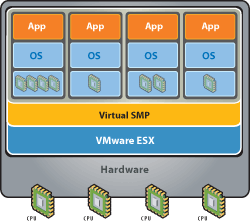
VMware® Virtual Symmetric Multi-Processing (SMP) enhances virtual machine performance by enabling a single virtual machine to use multiple physical processors, simultaneously. A unique VMware feature, Virtual SMP™ enables virtualization of the most processor- and
resource-intensive enterprise applications such as databases, ERP and CRM.

How Is VMware Virtual SMP Used in the Enterprise?

  • Create development and testing environments that are more realistic and can be quickly and easily deployed
  • Run resource intensive applications in virtualized environments.
  • Run enterprise application such as databases, and ERP or CRM, in virtual machines.
  • Scale computing environments without adding new hardware. Allow multiple processors to work together on a workload and increase utilization of existing resources.
  • Improve software development and deployment.

How Does VMware Virtual SMP Work?

VMware Virtual SMP makes it possible for a single virtual machine to span up to four physical processors, or CPUs. These processors share the same memory, and work on any task regardless of the location of the task in memory. Virtual SMP co-schedules non-idle
virtual processors synchronously while allowing over-commitment of the processors. Idle virtual processors can be de-scheduled with the guest operating system running inside the virtual machine and then re-used for other tasks. Virtual SMP periodically moves processing tasks between the available processors to re-balance the work load. Virtual SMP has built-in controls to minimize overhead on the system.

General Information

  • Poor performance of servers (if any) can be attributed to too many CPUs (as the wait time for CPU can increase if there are too any CPUs e.g. for a ‘single’threaded’ app on a a multi-vcpu VM)….
  • As long as the operating system is designed to support SMP then the operating system is responsible for balancing the processes among all the available CPUs as evenly as it can.  In most cases, adding more CPUs to an SMP system does not increase throughput in direct proportion to the new resources because workloads cannot always take advantage efficiently of multiple CPUs. There is also some overhead involved in sharing resources and scheduling processes. For example, a four-CPU SMP system is not four times as productive as a single-CPU system. The efficiency of a multiple-CPU SMP system, versus a single-CPU system, is defined by the workload’s ability to scale, or the workload’s scaling ratio. This scaling ratio varies for different workloads.
  • SMP systems are also affected by the need for locking and synchronization of resources. Before a task can modify a shared data item, it must ensure that no other task will change the data item. This is usually done by means of a lock. While a process or thread is waiting to obtain a lock, it is not productive. Further, while a thread is waiting for the lock, some of its cache lines may be replaced. Thus, when the thread is scheduled again, it may experience higher memory latency. The operating system’s kernel contains many shared data items, so it must perform synchronization internally. Synchronization delays can occur even in an application program that does not share data with other programs because the kernel services have to serialize shared kernel data. In addition to lock contention, path length also increases because more code is being executed.
  • The main advantage of deploying an SMP system is the ability to use multiple processors simultaneously to execute different tasks constituting a program, thereby increasing the throughput (for example, the number of transactions per second), compared to a single-CPU system. Only workloads that support parallelisation (including multiple processes or multiple threads that can run in parallel) can benefit from SMP. Single-threaded workloads can be scheduled to only one CPU at the time; and thus, cannot take advantage of additional CPUs being available. On the other hand, some modern applications with significant computational components have built in multi-threaded structures and a high scalability ratio. Good examples of the latter are Microsoft® SQL Server and Microsoft Exchange. Microsoft recommends deploying these applications on SMP systems with at least two CPUs

vMotion and NIC Teaming

vSphere 4 vMotion and NIC Teaming

In vSphere4 you can have only one VMkernel port for vMotion, so for network balance you have to use IP hash with Etherchannel
In vSphere 5 you can   have multiple VMkernel so you can balance vMotion  traffic across all NICs without any extra configuration on physical switch.

vSphere 5 vMotion and NIC Teaming

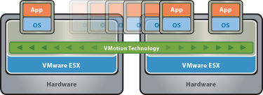
Among the many new networking features introduced in vSphere 5, perhaps one of the more significant improvements is multi-NIC support for vMotion.  This new enhancement will allow vSphere 5 to leverage multiple network adapters (in parallel) for a vMotion operation.  Previous releases, including vSphere 4.0 and 4.1, limited vMotion iterations to the bandwidth of a single network adapter.  Multi-NIC vMotion does not require any physical port configurations or load balancing option

Supported number of adapters for vMotion in vSphere 5 (per host):

1GbE – 16 NICs
10GbE – 4 NICs

Concurrent vMotions in vSphere 5 (per host):

1GbE – 4 vMotion operations
10GbE – 8 vMotion operations

Configuration

You will need to bind each VMkernel Interface (vmknic) to a physical NIC.

  • Create a VMkernel Interface and give it the name “vMotion-01″
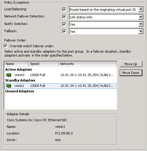
  • Go to the settings of this Portgroup and configure 1 physical NIC-port as active and all others as “standby” (see the screenshot below for an example)
  • Create a second VMkernel Interface and give it the name “vMotion-02″
  • Go to the settings of this Portgroup and configure a different NIC-port as active and all others as “standby

When you will initiate a vMotion multiple NIC ports can be used. Keep in mind that even when you vMotion just 1 virtual machine both links will be used. Also, if you don’t have dedicated links for vMotion you might want to consider using Network I/O Control. vMotion can saturate a link and at least when you’ve set up Network I/O Control and assigned the right amount of shares each type of traffic will get what it has been assigned.

YouTube Video Guide to Multi NIC vMotion setup

http://youtu.be/7njBRF2N0Z8

Example Setup (Thanks to Scott Aisenstat)

http://virtualistmanifesto.com/2011/10/06/vsphere-5-networking-multi-nic-vmotion/

Implementing Microsoft Network Load Balancing in a Virtualized Environment

Network Load Balancing is a feature of recent Microsoft server operating systems, including Windows 2000 Advanced Server, Windows Server 2003, and Windows Server 2008. This clustering technology enables you to improve the scalability and availability of Internet server programs, such as Web servers, proxy servers, DNS servers, FTP servers, virtual private network servers, streaming media servers, and terminal services servers.
In addition, it can detect host failures and automatically redistribute traffic to servers that are still operating.
In a VMware® Infrastructure 3 environment, you can create a cluster for Network Load Balancing using virtual machines on the same host or virtual machines on multiple hosts.

Network Load Balancing Basics

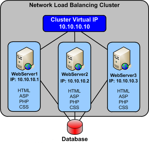
Network Load Balancing is implemented in a special driver installed on each Windows host in a cluster. The cluster presents a single IP address to clients. When client requests arrive, they go to all hosts in the cluster, and an algorithm implemented in the driver maps each request to a particular host. The other hosts in the cluster drop the request. You can set load partitioning to distribute specified percentages of client connections to particular hosts. You also have the option of routing all requests from a particular client to the host that handled that client’s first request.
Hosts in the cluster exchange heartbeat messages so they can maintain consistent information about what hosts are members of the cluster. If a host fails, client requests are rebalanced across the remaining hosts, with each remaining host handling a percentage of requests proportional to the percentage you specified in the initial configuration.

Planning a Network Load Balancing Cluster

Network Load Balancing relies on the fact that incoming packets are directed to all cluster hosts and passed to the Network Load Balancing driver for filtering.
You can configure a Network Load Balancing cluster in one of the following modes:

  • Multicast

Multicast mode allows communication among hosts because it adds a Layer 2 multicast
address to the cluster instead of changing the cluster. Communication among hosts is possible because the hosts retain their original unique media access control (MAC) addresses and already have unique, dedicated IP addresses. However, the address resolution protocol (ARP) reply that is sent by a host in the cluster (in response to an ARP request) maps the cluster’s unicast IP address to its multicast MAC address.
Some routers do not support the resolution of unicast IP addresses to multicast MAC addresses, and they discard the ARP reply. As a result, an administrator must add a static ARP entry in the router, mapping the cluster IP address to its MAC address.

NOTE VMware recommends that you use multicast mode, because unicast mode forces the physical switches on the LAN to broadcast all Network Load Balancing traffic to every machine on the LAN.

  • Unicast

Unicast mode works seamlessly with all routers and Layer 2 switches. However, this mode induces switch flooding, a condition in which all switch ports are flooded with NLB Traffic, even ports to which servers which not involved in NLB are attached. To communicate among hosts, you must have a second virtual adapter for each host.
Normally, switched environments avoid port flooding when a switch learns the MAC addresses of the hosts that are sending network traffic through it. The Network Load Balancing cluster masks the cluster’s MAC address for all outgoing traffic to prevent the switch from learning the MAC address.

On an ESX host, the VMkernel sends a reverse address resolution protocol (RARP) packet each time certain actions occur—for example, when a virtual machine is powered on, when there is a teaming failover, or when certain VMotion operations occur. The RARP packet gives physical switches the MAC address of the virtual machine involved in the action. In a Network Load Balancing cluster environment, after a Network Load Balancing node is powered on, the notification in the RARP packet exposes the MAC address of the cluster NIC. As a result, switches might begin to send all inbound traffic destined for the Network Load Balancing cluster through one switch port to a single node of the cluster.

Because the virtual switch operates with complete data about the underlying MAC addresses of the virtual NICs inside each virtual machine, it always correctly forwards packets containing a MAC address matching that of a running virtual machine. As a result of this behavior, the virtual switch does not forward traffic destined for the Network Load Balancing MAC address outside the virtual environment into the physical network, because it is able to forward it to a local virtual machine

Configuring Network Load Balancing in Windows

  1. Install a Windows operating system that supports Network Load Balancing in your virtual machines.
  2. You should install two virtual NICs in each virtual machine that will be part of the Network Load Balancing cluster. One virtual NIC from each virtual machine is used for Network Load Balancing. The other virtual NIC is used for management of the Windows virtual machine.
  3. Each Network Load Balancing node requires a static IP address to be assigned to the Network Load Balancing‐bound adapter. You need one or more additional static IP addresses to be used as the virtual IP addresses of the Network Load Balancing cluster. Use IP addresses that belong to the same subnet.
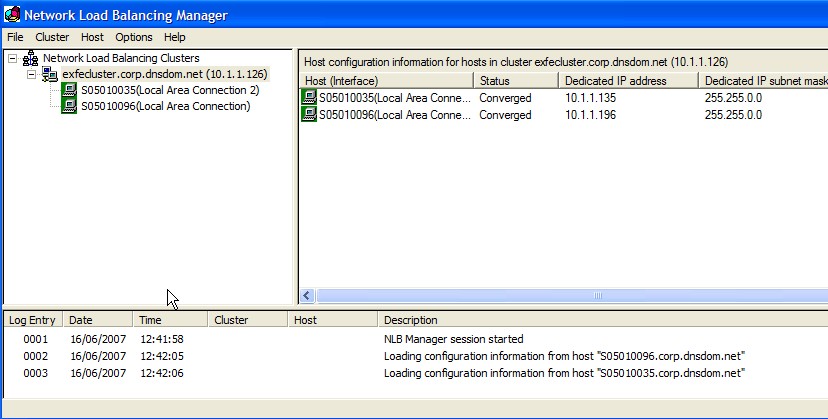
  4. Configure Network Load Balancing options using one of the following: Network Load Balancing Manager or Network Load Balancing Properties dialog box accessed through Network Connections
  5. VMware recommends that you use the Network Load Balancing Manager.
    Using both Network Load Balancing Manager and Network Connections to change Network Load Balancing properties can lead to unpredictable results.

You can use Network Load Balancing Manager from inside a node or from a remote machine that can communicate with all nodes. By default, Network Load Balancing Manager is installed on Windows Server 2003, and you can access it by clicking Settings > Control Panel > Administrative Tools > Network Load Balancing Manager.

Configuring Multicast Mode on VMware Switches

You do not need to take any special steps to configure your ESX host when you are using multicast mode.

Configuring Unicast Mode VMware Switches

This procedure helps prevent RARP packet transmission for the virtual switch as a whole. This setting affects all the port groups that use the switch. To prevent RARP Packet Transmission for a Virtual Switch, do the following

  1. Log on to the VI Client and select the ESX host.
  2. Click the Configuration tab.
  3. Choose Networking and, for the virtual switch, select Properties.
  4. On the Ports tab, select the virtual switch and click Edit.
  5. Click the NIC Teaming tab, set Notify Switches to No.
  6. Click OK and close the vSwitch Properties dialog box

Complete the following steps to prevent RARP packet transmission only for an individual port group. This setting overrides the setting you make for the virtual switch.

  1. Log on to the VI Client and select the ESX host.
  2. Click the Configuration tab.
  3. Choose Networking and, for the virtual switch, select Properties
  4. On the Ports tab, select the port group and click Edit.
  5. Click the NIC Teaming tab, set Notify Switches to No.
  6. Click OK and close the vSwitch Properties dialog box.
  7. Click OK and close the vSwitch Properties dialog box.

What happens to the Packets?

  • The packets/connections simply reach the network adaptor of each machine in the cluster
  • The NLB module sits right on top of the adaptor driver and receives the packet
  • Based on the source ip address of the client and/OR the port number of the client, an algorithm in the NLB module of each server in the cluster decides whether they should pickup this connection or not
  • The algorithm guarantees that only one machine in the cluster will pick up the packet. Think of this as an agree-upon horizontal partitioning strategy. For instance a trivial implementation could be, that in a two machine cluster – machine 1 picks up all connections with odd ip addresses and machine 2 picks up all connections with even IP addresses. This strategy is fool proof and does not require any communication between the machines at all. The actual algorithm is a randomization algorithm that uses more than just the client ip address (based on configuration) to determine whether it should pick up that packet
  • If the NLB module figures that this packet should be picked up by it, it simply passes it through the stack upwards. If not it simply discards the packet at this stage itself
  • NLB supports differential load balancing configurations wherein one can specify unequal distribution of load between machines in a cluster and its algorithm will automatically take care of it
  • NLB also maintains a heartbeat between machines and if any machine is found to be down, it will automatically redistribute the load amongst the remaining machines
  • NLB also supports client_affinity (another name for sticky sessions) where in connections originating from a single IP will be sent to a single source. This can screw up if one is using a reverse-proxy in front of the cluster, since all connections will appear to originate from a single ip address. One should not enable client_affinity if one has a reverse proxy. In most cases if you have a reverse-proxy, the reverse-proxy itself can perform relevant load balancing, so NLB would be redundant

As new machines join or are removed from the cluster, in order for the load to be distributed correctly among all active nodes, the algorithm must be re-executed in an extremely important re-evaluation process called convergence. It is also important to realize that at no time is NLB ever aware of what the load is on any particular cluster node because NLB cannot determine whether a node’s CPU usage is extremely high or that a node has little to no available memory to process a request

Advantages of NLB

  • Network Load Balancing is very efficient and can provide a very big performance improvement for each machine added into the cluster.
  • NLB has a fault tolerance capability. Many other load balancing implementations, such as Round Robin DNS (RRDNS), continue to send requests to servers that have “died” until system administrators pick up on the fact that there is a problem and then manually perform a configuration change. The key is redundancy in addition to load balancing; if any machine in the cluster goes down, NLB will re-balance the incoming requests to the still running servers thus handling scenarios where a power supply has burnt out, a network card has gone bad, the primary hard disk has crashed, etc
  • This level of redundancy increasing the load balancing capability becomes simply a matter of adding machines to the cluster, which results in a practically unlimited application scalability.
  • NLB works with any TCP or UDP application-based protocol. This means that it’s possible to configure a variety of NLB clusters within an organization, and each one can have its own specific function. For example, one cluster may be dedicated to handling all Internet-originated HTTP traffic while another may be used to serve all intranet requests. If the employees have a need for transferring files, there can be a FTP cluster acting as centralized file storage with closely monitored uploads and downloads
  • By far, one of the biggest advantages of NLB is its ease of use. NLB installs only a networking driver component – absolutely no special hardware is required. Not only does this facilitate the deployment of a load balancing solution, but it also significantly reduces costs

References

  • “Checklist: Enabling and configuring Network Load Balancing”

http://go.microsoft.com/fwlink/?LinkId=18371

  • Reasons for using NLB

http://technet2.microsoft.com/windowsserver/en/library/7698646d‐510e‐47f9‐9b09‐b31dec12be3a1033.mspx

VMware vApps

What is a vApp?

You can use VMware vSphere as a platform for running applications, in addition to using it as a platform for running virtual machines. The applications can be packaged to run directly on top of VMware vSphere. The format of how the applications are packaged and managed is called vSphere vApp.
A vApp is a container, like a resource pool and can contain one or more virtual machines. A vApp also shares some functionality with virtual machines. A vApp can power on and power off, and can also be cloned.
In the vSphere Client, a vApp is represented in both the Host and Clusters view and the VM and Template view. Each view has a specific summary page with the current status of the service and relevant summary information, as well as operations on the service.

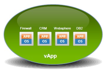
A vApp is basically a resource container for multiple virtual machines that work together as part of a multi-tier application.

The three applications on each server all work together and are mostly dependent on each other for the application to function properly. If one part of the tier became unavailable, the application will typically quit working as it relies on all the tiers for the application to work.

Virtualization can introduce some challenges with multi-tier applications. For example, if one tier is performing poorly due to resource constraints on a host, then the whole application will suffer as a result. Another challenge comes when powering on a host server, as often times one tier relies on another tier to be started first or the application will fail.

VMware introduced vApps as a method to deal with these problems by providing methods for setting power-on options, IP address allocation and resource allocation, and provide application-level customization for all the virtual machines in the vApp. When you configure a vApp in vSphere you specify properties for it, including CPU and memory resources, IP allocation, application information, and start order.

Distribution Format

The distribution format for vApp is OVF.

Note

The vApp metadata resides in the vCenter Server’s database, so a vApp can be distributed across multiple ESXi hosts. This information can be lost if the vCenter Server database is cleared or if a standalone ESXi host that contains a vApp is removed from vCenter Server. You should back up vApps to an OVF package to avoid losing any metadata.
vApp metadata for virtual machines within vApps do not follow the snapshots semantics for virtual machine configuration. So, vApp properties that are deleted, modified, or defined after a snapshot is taken remain intact (deleted, modified, or defined) after the virtual machine reverts to that snapshot or any prior snapshots.

Where can you create a vApp?

After you create a datacenter and add a clustered host enabled with DRS or a standalone host to your vCenter Server system, you can create a vApp.

You can create a vApp under the following conditions.

  • A standalone host is selected in the inventory that is running ESX 3.0 or greater.
  • A cluster enabled with DRS is selected in the inventory.
  • You can create vApps on folders, standalone hosts, resource pools, clusters enabled with DRS, and within other vApps.

Creating a vApp

  • Right click on a cluster or a host and select New vApp

  • Put in a name and select the Inventory location
  • Click Next

  • Adjust resources accordingly and click Next and Finish

Once you are done configuring a vApp, you can add virtual machines (VMs) to it by dragging them using the vSphere client. You can also create resource pools inside of them and nest vApps inside of vApps. If you edit the settings of a VM, select the Options tab, and then select vApp Options, you can enable the vApp functionality for the VM and set individual vApp options for the VM. Once you have created a vApp you can easily export it in Open Virtualization Format (OVF) format, as well as deploy new vApps from one that are already created

  • Go to the vApp in the Hosts and Clusters View and select Edit Settings. You can edit the CPU and memory resource allocation for the vApp

  • Click on Start Order. You can change the order in which virtual machines and nested vApps within a vApp start up and shut down. You can also specify delays and actions performed at startup and shutdown

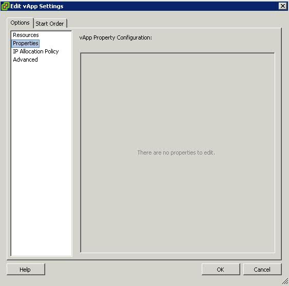
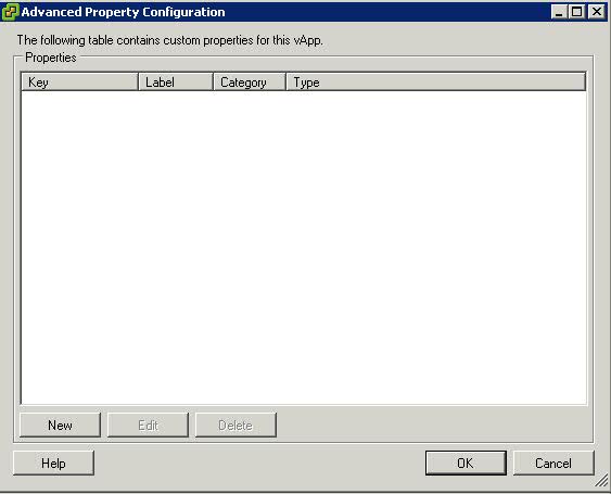
  • Click on Properties. You can edit any vApp property that is defined in Advanced Property Configuration

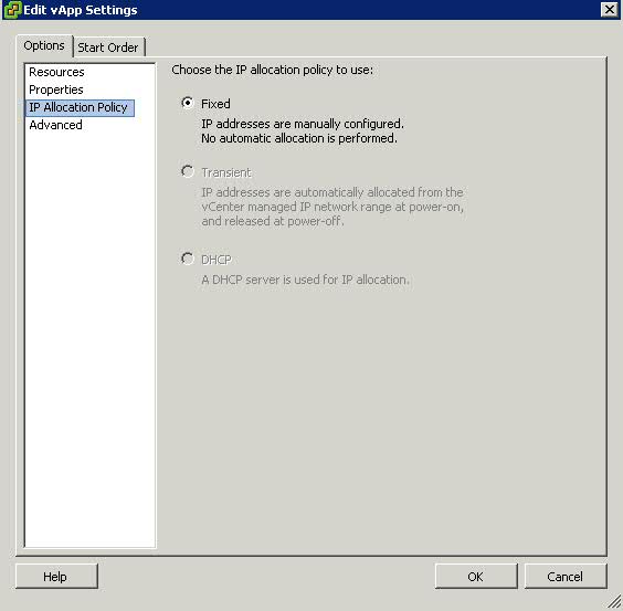
  • Click on IP Allocation Policy. You can edit how IP addresses are allocated for the vApp.

Fixed = IP addresses are manually configured. No automatic allocation is performed

Transient = IP addresses are automatically allocated using IP pools from a specified range when the vApp is powered on. The IP addresses are released when the appliance is powered off.

DHCP = A DHCP server is used to allocate the IP addresses. The addresses assigned by the DHCP server are visible in the OVF environments of virtual machines started in the vApp.

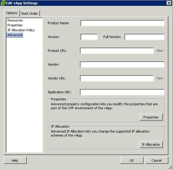
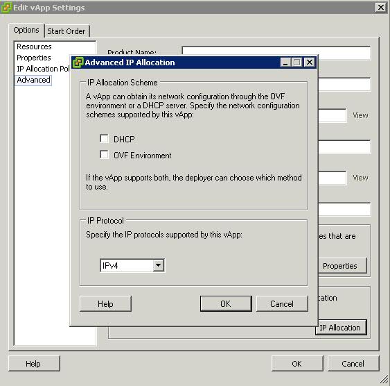
  • Click on Advanced. You can edit and configure advanced settings, such as product and vendor information, custom properties, and IP allocation


Enabling Host Monitoring in HA Clusters

VMware HA clusters enable a collection of ESX/ESXi hosts to work together so that, as a group, they provide higher levels of availability for virtual machines than each ESX/ESXi host could provide individually. When you plan the creation and usage of a new VMware HA cluster, the options you select affect the way that cluster responds to failures of hosts or virtual machines.
Before creating a VMware HA cluster, you should be aware of how VMware HA identifies host failures andisolation and responds to these situations. You also should know how admission control works so that you can choose the policy that best fits your failover needs. After a cluster has been established, you can customize its behavior with advanced attributes and optimize its performance by following recommended best practices.

How VMware HA works

VMware HA provides high availability for virtual machines by pooling them and the hosts they reside on into a cluster. Hosts in the cluster are monitored and in the event of a failure, the virtual machines on a failed host are restarted on alternate hosts.

Primary and Secondary Hosts in a VMware HA Cluster

When you add a host to a VMware HA cluster, an agent is uploaded to the host and configured to communicate with other agents in the cluster. The first five hosts added to the cluster are designated as primary hosts, and all subsequent hosts are designated as secondary hosts. The primary hosts maintain and replicate all cluster state and are used to initiate failover actions. If a primary host is removed from the cluster, VMware HA promotes another host to primary status.
Any host that joins the cluster must communicate with an existing primary host to complete its configuration (except when you are adding the first host to the cluster). At least one primary host must be functional for VMware HA to operate correctly. If all primary hosts are unavailable (not responding), no hosts can be successfully configured for VMware HA.

Failure Detection and Host Network Isolation

Agents communicate with each other and monitor the liveness of the hosts in the cluster. This is done through the exchange of heartbeats, by default, every second. If a 15-second period elapses without the receipt of heartbeats from a host, and the host cannot be pinged, it is declared as failed. In the event of a host failure, the virtual machines running on that host are failed over, that is, restarted on the alternate hosts with the most available unreserved capacity (CPU and memory.)

Note: In the event of a host failure, VMware HA does not fail over any virtual machines to a host that is in maintenance mode, because such a host is not considered when VMware HA computes the current failover level. When a host exits maintenance mode, the VMware HA service is re-enabled on that host, so it becomes available for failover again.

Host network isolation occurs when a host is still running, but it can no longer communicate with other hosts in the cluster. With default settings, if a host stops receiving heartbeats from all other hosts in the cluster for more than 12 seconds, it attempts to ping its isolation addresses. If this also fails, the host declares itself as isolated from the network.
When the isolated host’s network connection is not restored for 15 seconds or longer, the other hosts in the cluster treat it as failed and attempt to fail over its virtual machines. However, when an isolated host retains access to the shared storage it also retains the disk lock on virtual machine files. To avoid potential data corruption, VMFS disk locking prevents simultaneous write operations to the virtual machine disk files and attempts to fail over the isolated host’s virtual machines fail. By default, the isolated host shuts down its virtual
machines, but you can change the host isolation response to Leave powered on or Power off

Redundancy and Reducing Isolation

If you ensure that your network infrastructure is sufficiently redundant and that at least one network path is available at all times, host network isolation should be a rare occurrence.

Which setting should I use?

  • Shutdown

It depends. Some people prefer “Shut down” because they do not want to use a deprecated host and it will shut down your VMs in a clean manner.

The isolation response is a setting that needs to be taken into account when you create your design. For instance when using an iSCSI array or NFS choosing “leave powered on” as your default isolation response might lead to a split-brain situation depending on the version of ESX used. The reason for this being that the disk lock times out if the iSCSI network is also unavailable. In this case the VM is being restarted on a different host while it is not being powered off on the original host. In a normal situation this should not lead to problems as the VM is restarted and the host on which it runs owns the lock on the VMDK, but for some weird reason when disaster strikes you will not end up in a normal situation but you might end up in an exceptional situation

  • Leave Powered On

Many people prefer to use “Leave powered on” because it reduces the chances of a false positive. A false positive in this case is an isolated heartbeat network but a non-isolated VM network and a non-isolated iSCSI / NFS network.

How does HA knows if the host is isolated or completely unavailable when you have selected “leave powered on”?

HA actually does not know the difference. HA will try to restart the affected VMs in both cases. When the host has failed a restart will take place, but if a host is merely isolated the non-isolated hosts will not be able to restart the affected VMs. This is because of the VMDK file lock; no other host will be able to boot a VM when the files are locked. When a host fails this lock starves and a restart can occur.

Isolation Response Considerations

The default value for isolation/failure detection is 15 seconds. In other words the failed or isolated host will be declared dead by the other hosts in the HA cluster on the fifteenth second and a restart will be initiated by one of the primary hosts.

For now let’s assume the isolation response is “power off”. The “power off”(isolation response) will be initiated by the isolated host 1 second before the das.failuredetectiontime. A “power off” will be initiated on the fourteenth second and a restart will be initiated on the fifteenth second.

Does this mean that you can end up with your VMs being down and HA not restarting them?
Yes, when the heartbeat returns between the 14th and 15th second the “power off” could already have been initiated. The restart however will not be initiated because the heartbeat indicates that the host is not isolated anymore.

How can you avoid this?

Pick “Leave VM powered on” as an isolation response. Increasing the das.failuredetectiontime will also decrease the chances of running in to issues like these.

Basic design principle: Increase “das.failuredetectiontime” to 30 seconds (30000) to decrease the likely-hood of a false positive

Please see the below link for further information on this

http://rickardnobel.se/vmware-ha-das-failuredetectiontime/

Changing the IP Address of the SQL Database Server

If like us, you need to change the IP Address of you vCenter Database server, here are a few pointers

vCenter accesses the DB through an ODBC connection. That’s normally
configured with a FQDN or shortname  rather than an IP address so the
change shouldn’t cause a problem.

You can test it by going to Start –> Administrative Tools –> Data source
(ODBC). Open that up and click on the ‘System DSN’ tab.

Select the vCenter DSN and click on configure. From there you can run
through the wizard without changing anything and at the end there is ‘Test
connection button’. If that works you should be good to go

As long as your DNS servers are up to date there shouldn’t be an issue.