Determine requirements for and configure NPIV

Going-way-too-fast-coloring-page.png

What does NPIV stand for?

(N_Port ID Virtualization)

What is an N_Port?

An N_Port is an end node port on the Fibre Channel fabric. This could be an HBA (Host Bus Adapter) in a server or a target port on a storage array.

What is NPIV?

N_Port ID Virtualization or NPIV is a Fibre Channel facility allowing multiple N_Port IDs to share a single physical N_Port. This allows multiple Fibre Channel initiators to occupy a single physical port, easing hardware requirements in Storage Area Network design, especially where virtual SANs are called for. NPIV is defined by the Technical Committee T11 in the Fibre Channel – Link Services (FC-LS) specification

NPIV  allows a single host bus adaptor (HBA) or target port on a storage array to register multiple World Wide Port Names (WWPNs) and N_Port identification numbers.  This allows each virtual server to present a different world wide name to the storage area network (SAN), which in turn means that each virtual server will see its own storage — but no other virtual server’s storage

How NPIV-Based LUN Access Works

NPIV enables a single FC HBA port to register several unique WWNs with the fabric, each of which can be assigned to an individual virtual machine.

SAN objects, such as switches, HBAs, storage devices, or virtual machines can be assigned World Wide Name (WWN) identifiers. WWNs uniquely identify such objects in the Fibre Channel fabric. When virtual machines have WWN assignments, they use them for all RDM traffic, so the LUNs pointed to by any of the RDMs on the virtual machine must not be masked against its WWNs. When virtual machines do not have WWN assignments, they access storage LUNs with the WWNs of their host’s physical HBAs. By using NPIV, however, a SAN administrator can monitor and route storage access on a per virtual machine basis. The following section describes how this works.

When a virtual machine has a WWN assigned to it, the virtual machine’s configuration file (.vmx) is updated to include a WWN pair (consisting of a World Wide Port Name, WWPN, and a World Wide Node Name, WWNN). As that virtual machine is powered on, the VMkernel instantiates a virtual port (VPORT) on the physical HBA which is used to access the LUN. The VPORT is a virtual HBA that appears to the FC fabric as a physical HBA, that is, it has its own unique identifier, the WWN pair that was assigned to the virtual machine. Each VPORT is specific to the virtual machine, and the VPORT is destroyed on the host and it no longer appears to the FC fabric when the virtual machine is powered off. When a virtual machine is migrated from one ESX/ESXi to another, the VPORT is closed on the first host and opened on the destination host.

If NPIV is enabled, WWN pairs (WWPN & WWNN) are specified for each virtual machine at creation time. When a virtual machine using NPIV is powered on, it uses each of these WWN pairs in sequence to try to discover an access path to the storage. The number of VPORTs that are instantiated equals the number of physical HBAs present on the host. A VPORT is created on each physical HBA that a physical path is found on. Each physical path is used to determine the virtual path that will be used to access the LUN. Note that HBAs that are not NPIV-aware are skipped in this discovery process because VPORTs cannot be instantiated on them

Requirements

  • The fibre switch must support NPIV
  • The HBA must support NPIV.
  • RDMs must be used (Raw Device mapping)
  • Use HBAs of the same type, either all QLogic or all Emulex. VMware does not support heterogeneous HBAs on the same host accessing the same LUNs
  • If a host uses multiple physical HBAs as paths to the storage, zone all physical paths to the virtual machine. This is required to support multipathing even though only one path at a time will be active
  • Make sure that physical HBAs on the host have access to all LUNs that are to be accessed by NPIV-enabled virtual machines running on that host
  • When configuring a LUN for NPIV access at the storage level, make sure that the NPIV LUN number and NPIV target ID match the physical LUN and Target ID
  • Keep the RDM on the same datastore as the VM configuration file.

NPIV Capabilities

  • NPIV supports vMotion. When you use vMotion to migrate a virtual machine it retains the assigned WWN.
  • If you migrate an NPIV-enabled virtual machine to a host that does not support NPIV, VMkernel reverts to using a physical HBA to route the I/O
  • If your FC SAN environment supports concurrent I/O on the disks from an active-active array, the concurrent I/O to two different NPIV ports is also supported.

NPIV Limitations

  • Because the NPIV technology is an extension to the FC protocol, it requires an FC switch and does not work on the direct attached FC disks
  • When you clone a virtual machine or template with a WWN assigned to it, the clones do not retain the WWN.
  • NPIV does not support Storage vMotion.
  • Disabling and then re-enabling the NPIV capability on an FC switch while virtual machines are running can cause an FC link to fail and I/O to stop

Assign WWNs to Virtual Machines

You can create from 1 to 16 WWN pairs, which can be mapped to the first 1 to 16 physical HBAs on the host.

  • Open the New Virtual Machine wizard.
  • Select Custom, and click Next.
  • Follow all steps required to create a custom virtual machine.
  • On the Select a Disk page, select Raw Device Mapping, and click Next.
  • From a list of SAN disks or LUNs, select a raw LUN you want your virtual machine to access directly.
  • Select a datastore for the RDM mapping file.
  • You can place the RDM file on the same datastore where your virtual machine files reside, or select a different datastore.

Note: If you want to use vMotion for a virtual machine with enabled NPIV, make sure that the RDM file is located on the same datastore where the virtual machine configuration file resides.

  • Follow the steps required to create a virtual machine with the RDM.
  • On the Ready to Complete page, select the Edit the virtual machine settings before completion check box and click Continue.
  • The Virtual Machine Properties dialog box opens.
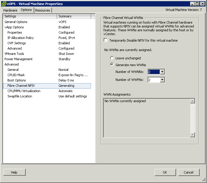
  • Click the Options tab, and select Fibre Channel NPIV
  • (Optional) Select the Temporarily Disable NPIV for this virtual machine check box
  • Select Generate new WWNs.
  • Specify the number of WWNNs and WWPNs.
  • A minimum of 2 WWPNs are needed to support failover with NPIV. Typically only 1 WWN is created for each virtual machine.
  • Click Finish.
  • The host creates WWN assignments for the virtual machine.

NPIV

What to do next

Register newly created WWN in the fabric so that the virtual machine is able to log in to the switch, and assign storage LUNs to the WWN

NPIV Advantages

  • Granular security: Access to specific storage LUNs can be restricted to specific VMs using the VM WWN for zoning, in the same way that they can be restricted to specific physical servers.
  • Easier monitoring and troubleshooting: The same monitoring and troubleshooting tools used with physical servers can now be used with VMs, since the WWN and the fabric address that these tools rely on to track frames are now uniquely associated to a VM.
  • Flexible provisioning and upgrade: Since zoning and other services are no longer tied to the physical WWN “hard-wired” to the HBA, it is easier to replace an HBA. You do not have to reconfigure the SAN storage, because the new server can be pre-provisioned independently of the physical HBA WWN.
  • Workload mobility: The virtual WWN associated with each VM follows the VM when it is migrated across physical servers. No SAN reconfiguration is necessary when the work load is relocated to a new server.
  • Applications identified in the SAN: Since virtualized applications tend to be run on a dedicated VM, the WWN of the VM now identifies the application to the SAN.
  • Quality of Service (QoS): Since each VM can be uniquely identified, QoS settings can be extended from the SAN to VMs

Identify Supported HBA types

ce-HBA-fig1a

HBA Adapters

The three types of Host Bus Adapters (HBA) that you can use on an ESXi host are

  • Ethernet (iSCSI)
  • Fibre Channel
  • Fibre Channel over Ethernet (FCoE).
  • In addition to the hardware adapters there is software versions of the iSCSI and FCoE adapters (software FCoE is new with version 5) are available.

Compatibility Guide

To see all the results search VMware’s compatibility guide

Determine use cases for and configure VMware DirectPath I/O

pci

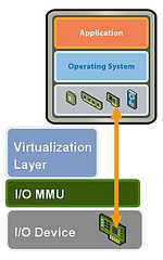
DirectPath I/O allows virtual machine access to physical PCI functions on platforms with an I/O Memory Management Unit.

The following features are unavailable for virtual machines configured with DirectPath

  • Hot adding and removing of virtual devices
  • Suspend and resume
  • Record and replay
  • Fault tolerance
  • High availability
  • DRS (limited availability. The virtual machine can be part of a cluster, but cannot migrate across hosts)
  •  Snapshots

Cisco Unified Computing Systems (UCS) through Cisco Virtual Machine Fabric Extender (VM-FEX) distributed switches support the following features for migration and resource management of virtual machines which use DirectPath I/O

  • Hot adding and removing of virtual devices
  • vMotion
  • Suspend and resume
  • High availability
  • DRS (limited availability
  •  Snapshots

Configure Passthrough Devices on a Host

  • Click on a Host
  • Select the Configuration Tab
  • Under Hardware, select Advanced Settings. You will see a warning message as per below

pass

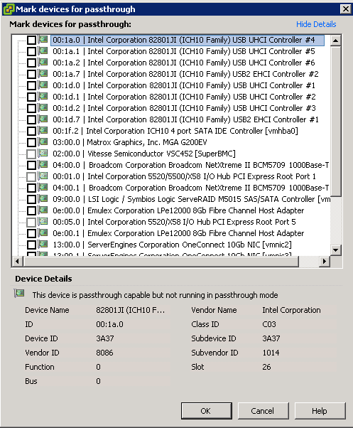
  • Click Configure Passthrough. The Passthrough Configuration page appears, listing all available passthrough devices.

passthrough

  • A green icon indicates that a device is enabled and active. An orange icon indicates that the state of the device has changed and the host must be rebooted before the device can be used

Capture

Configure a PCI Device on a VM

Prerequisites

Verify that a Passthrough networking device is configured on the host of the virtual machine as per above instructions

Instructions

  • Select a VM
  • Power off the VM
  • From the Inventory menu, select Virtual Machine > Edit Settings
  • On the Hardware tab, click Add.
  • Select PCI Device and click Next
  • Select the Passthrough device to use
  • Click Finish
  • Power on VM

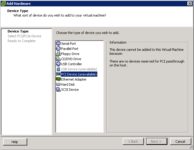
As per below I haven’t cofigured any pass thorugh devices but just to show you where the settings are

vmpci


Roaming Profiles and Redirecting Folders on Windows Server 2008 R2Terminal Servers

redirect

What is a Roaming Profile?

A roaming user profile is user data, stored in a specific folder structure, to follow users as they log on to and log off from different computers. Roaming user profiles are stored on a central server location. At log on, Windows copies the user profile from the central location to the local computer. When the user logs off, Windows copies changed user profile data from the client computer to the central storage location. This ensures that the client data follows users as they roam the environment.

Roaming user profiles solve part of the roaming problem, but it also creates added concerns. User profiles can increase in size, some as large as 20 megabytes or more. This increase causes delays in user logons, because it takes some time for Windows to copy the information to the local computer. Another concern with roaming user profiles is that they are saved only at logoff. Therefore, when a user logs on to one computer and changes data within their profile, the changes remain local and remain local until the user logs off, making real-time access to user data challenging in a roaming user environment. Folder Redirection reduces some of these problems.

Folder Redirection

Folder Redirection is a client side technology that provides an ability to change the target location of predetermined folders found within the user profile. This redirection is transparent to the user and gives the user a consistent way of saving their data, regardless of its storage location. Folder Redirection provides a way for administrators to divide user data from profile data. This division of user data decreases user logon times, and Windows downloads less data. Windows redirects the local folder to a central location, giving the user immediate access to their data when they save it, regardless of the computer they are using. This immediate access removes the need to update the user profile.

Folder Redirection helps with slow logons and missing data problems because the Application Data, Desktop, My Documents, My Pictures, and Start Menu can be supported by Folder Redirection in Windows XP/Vista/7

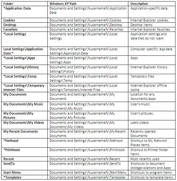
Windows XP Profile Folder Locations

* These directories are hidden by default. To see these directories, change the View Options.

XPLocation2

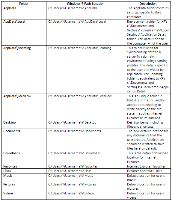
Windows 7 Profile Folder Locations

  • The biggest change is the location of the profiles themselves – the user profiles are now located under c:\users\<username> instead of c:\documents and settings\<username>
  • Appdata – This is now a combination of c:\documents and settings\\application data\ and c:\documents and settings\\local settings\ – this folder contains three folders – “Local”, “LocalLow” and “Roaming”

7Location2

Setting up a Profile and Home Directory Folder Requirements

Note: Profiles and Home Directories can be on the same server

  • A Profile Server
  • A Home Directory Server

Instructions

When setting up the file server you need to be sure that the permission on the folder are setup so that a user can create a new folder however you also need to ensure that they can only see their own files.

Note: When creating the Share, it is Best Practice to add a $ sign to the end of the Share which will keep it hidden from regular users

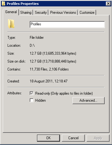
  • Create a new folder and call it Profiles

profile folder

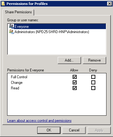
  • Click the Sharing tab and then click Advanced Sharing then click Permissions
  • Make sure the Everyone Group has Full Control
  • Make sure the Administrators Group has Full Control, you may have a differently named Admin Group so add as necessary
  • Make sure the SYSTEM group has Full Control

permissions

  • Click OK
  • Click on the Security Tab and Untick “Include inheritable permission form this object’s parent”
  • Click on the Security Tab and Select Advanced
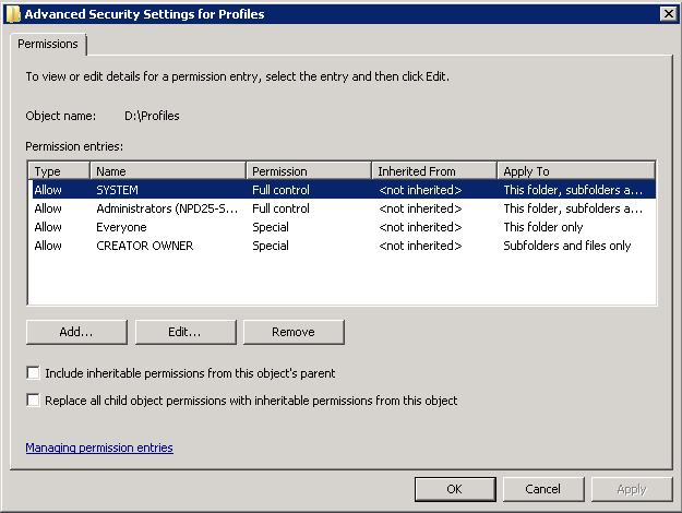
  • Select Change Permissions and make sure your permissions look like the below screenprint and conform to the below information
  • Configure the folder to not inherit permissions and remove all existing permissions.
  • Add the file server’s local Administrators group with Full Control of This Folder, Subfolders, and Files.
  • Add the Domain Admins domain security group with Full Control of This Folder, Subfolders, and Files.
  • Add the System account with Full Control of This Folder, Subfolders, and Files.
  • Add the Creator/Owner with Full Control of Subfolders and Files.
  • Add the Authenticated Users group with both List Folder/Read Data and Create Folders/Append Data – This Folder Only rights. The Authenticated Users group can be replaced with the desired group, but do not choose the Everyone group as a best practice.

The share permissions of the folder can be configured to grant administrators Full Control and authenticated users Change permissions.

perms2

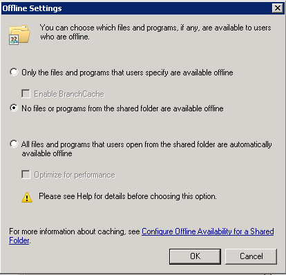
  • After you configure the share and security permissions, click on the Sharing tab and then the “Caching” button and select the “No Files or programs from the share folder are available offline” options then press OK then OK then Close.

caching

  • Next do exactly the same to create a shared folder for the Home Directory folder

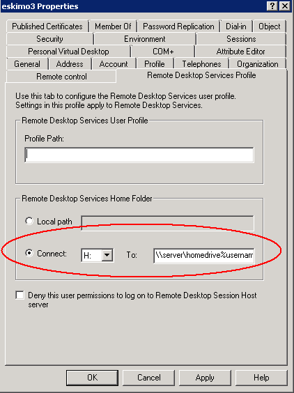
Setting up a User account with a Profile Path Remote Desktop Profile Path and Home Directory

NOTE: This can be controlled by Group Policy but do it manually while you test a user

NOTE: I had to put the same path in the Profile Path and the Remote Desktop Services Profile Path to get full roaming profile on my folders

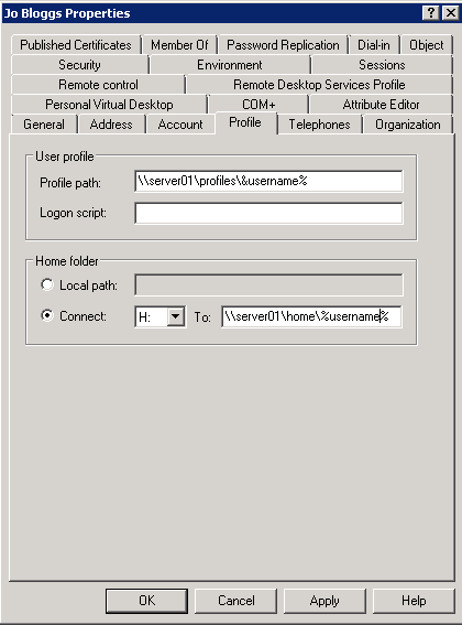
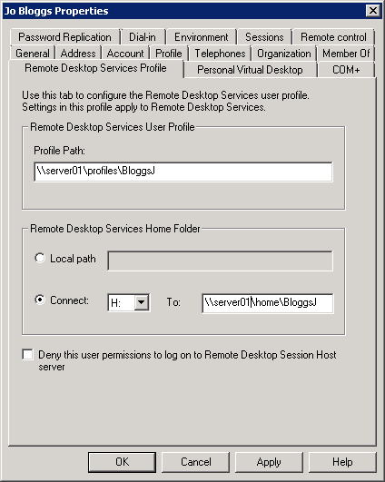
  • You configure the profile location for a user on the Profile or Remote Desktop Services Profile tab within Active Directory Users and Computers. Type a UNC path to where Windows should create the user profile. The following screen shots below give you an example a user account configured with a profile path and a Remote Desktop Services Profile
  • The folder redirection client side extension is only able to process two environment variables: %username% and %userprofile%. Other environment variables such as %logonserver%, %homedrive% and %homepath% will not work with folder redirection.

profiles2

  • And also add the same for the Remote Desktop Services Profile (Note this can be controlled by Group Policy as detailed at the end of this document. For now, I’ve just added it in manually so you can see where it is)

rdprofile

Setting up Group Policy for re-directing User Profile folders

  • To start the Group Policy snap-in from the Active Directory Users and Computers snap-in, click Start, point to Programs, click Administrative Tools, and then click Group Policy Management
  • In the MMC console tree, right-click the domain or the OU for which to access Group Policy and select  Create a GPO in this domain and link it here
  • Click New, and type the name to use for the GPO. For example, type Roaming Profile GPO
  • Expand the OU so you can see the new Policy and right click and Edit to open the Group Policy
  • Click Edit to open the Group Policy snap-in and edit the new GPO
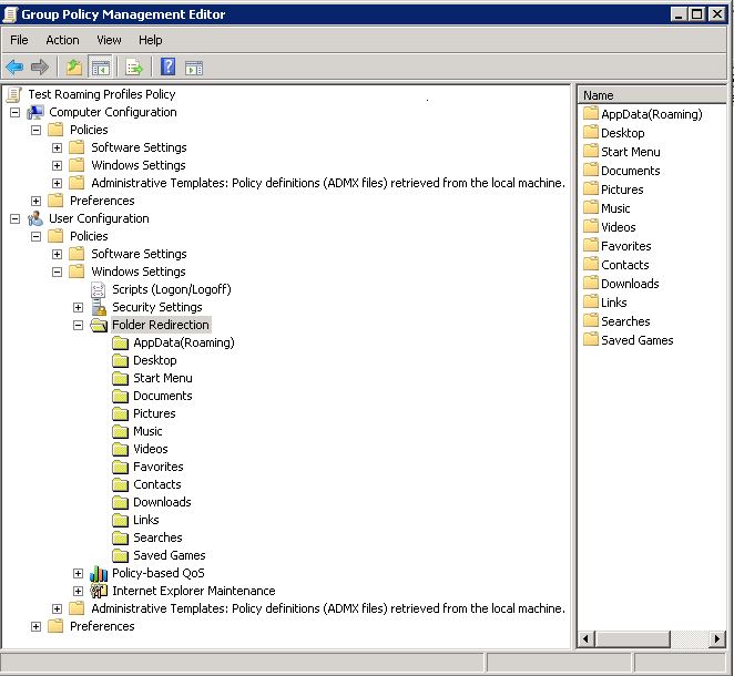
  • In the Group Policy console, expand the User Configuration, Policies, Windows Settings, and Folder Redirection nodes. Icons for the personal folders that can be redirected will be displayed

gpfolders1

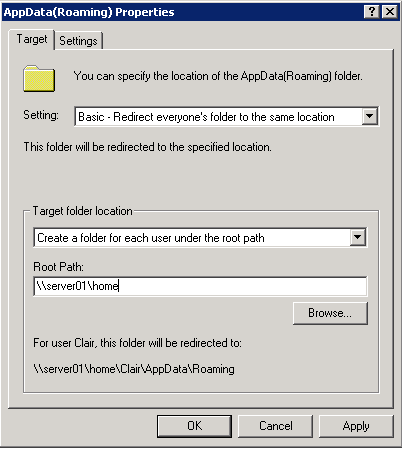
  • Right click on AppData (Roaming) and select Properties
  • There are 3 settings to choose from –  Not Configured, Basic Redirection and Advanced Redirection

Basic Redirection and Advanced Redirection are available to all folders listed in the snap-in. You use basic redirection when you store the selected folder in the Group Policy object on the same share for all users. You use Advanced Redirection when you want to redirect the selected folder to a different location based on a security group membership of the user. For example, you would use Advanced Folder Redirection when you want to redirect folders belonging to the Accounting group to the Finance server and folders belonging to the Sales group to the Marketing server

  • Choose Basic – Redirect everyone’s folder to the same location
  • Choose Create a folder for each user under the root path
  • Type the root path to the shared folder

appdatar

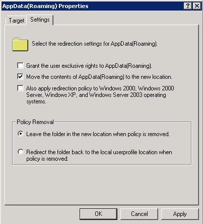
  • Click Settings
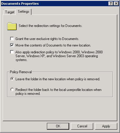
  • Untick Grant the User Exclusive rights to AppData(Roaming)

If you leave “Grant the user exclusive rights to Documents” ticked then when the folder is initially setup Windows will block inheritance on the folder and grant exclusive access to the users on these files. This will lockout even administrators to the files which makes administration of these folders very difficult. If an administrator did need to access these files they will need to take ownership which in turn removes access from the users to their files. The admin will then need to ensure that they need to re-setup the permission on the folder to ensure that they users can still access the files.

gpappdatasettings

  • Only apply redirection policy when you have multiple O/S’s
  • Generally recommended for Policy Removal to Leave the folder in the new location when the policy is removed
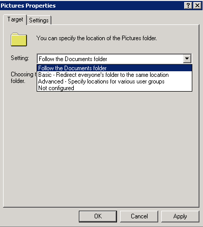
  • The Pictures, Music and Videos Properties page provides an additional options for the folder as seen in the below screenprint: Follow the Documents Folder

gppictures

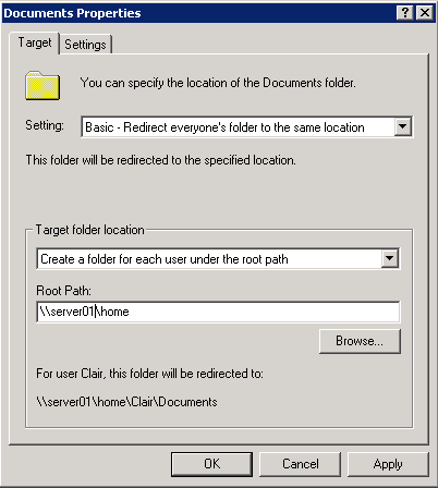
  • When it comes to the My Documents/Documents folder there are several options again
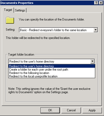
  • Note: Unlike Windows 2000, you do not need to type in the %username% variable. The folder redirection code will automatically create a My Documents folder for each user, inside a folder based on their user name. For example, type \\FolderServer\MyDocumentsFolders rather than \\FolderServer\MyDocumentsFolders\%username% as you would on Windows 2000.

docsnew1

  • Click the Settings Tab
  • By default, Administrators do not have permissions to users’ redirected folders. If you require the ability to go into the users folders you will want to go to the “Settings” Tab, and uncheck: “Grant the user exclusive rights to” on each folder that is redirected. This allows Administrators to enter the users redirected folder locations without taking ownership of the folder and files.

docsnew2

  • Note: If you already have a shared home folder as we set up earlier, it is best not to select Redirect to the Users Home Directory. See Link below for more info

http://support.microsoft.com/kb/321805

gpdocuments_homedir

  • Go through all the rest of the folders you want to redirect
  • Finish

When you enable folder redirection for users for the first time, you will find the logon to be very slow. You are in effect copying the contents of all the user’s personal folders across the network to the server and you can imagine the effect if you are doing this for multiple users at the same time when the login. Before applying this policy to an OU containing hundreds of users, it may be worth creating a new OU and migrating a few users at a time across and will also help you troubleshoot easier without thousands of helpdesk calls about profiles.

You can enable Access based Enumeration however if there is going to a lot of user folders on any one of these shares you could experience degradation of performance. Enabling ABE on a share does come at a price of performance

Other Group Policy Settings

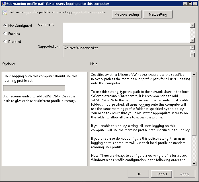
  • Setting the same Roaming Profile path for all users logging on

Navigate to Computer Configuration > Policies > Administrative Templates > System > User Profiles and enable the “Set roaming profile path for all users logging onto this computer” and configure the path to the shared folder for profiles.

gp1

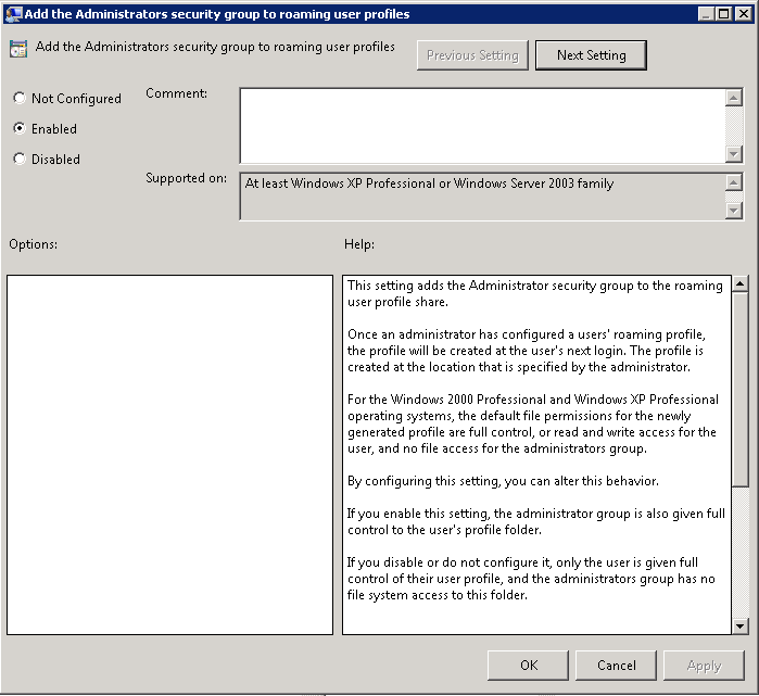
  • Add the Administrators Security Group to roaming user profiles

Navigate to Computer Configuration > Policies > Administrative Templates > System > User Profiles and enable the “Add the Administrators Security Group to roaming user profiles”

gp2

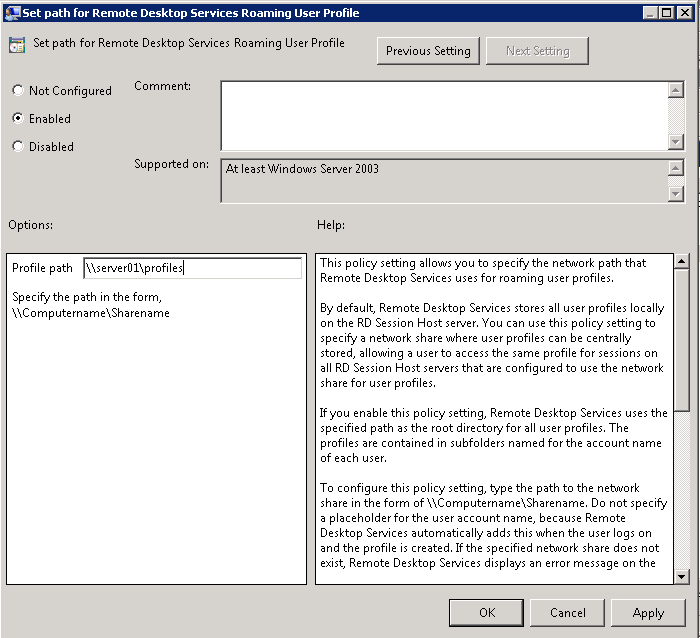
  • Set Path for the Remote Desktop Services Roaming User Profile

Navigate to Computer Configuration > Policies > Administrative Templates > Windows Components > Remote Desktop Services > Remote Desktop Session Host\Profiles

rdgp

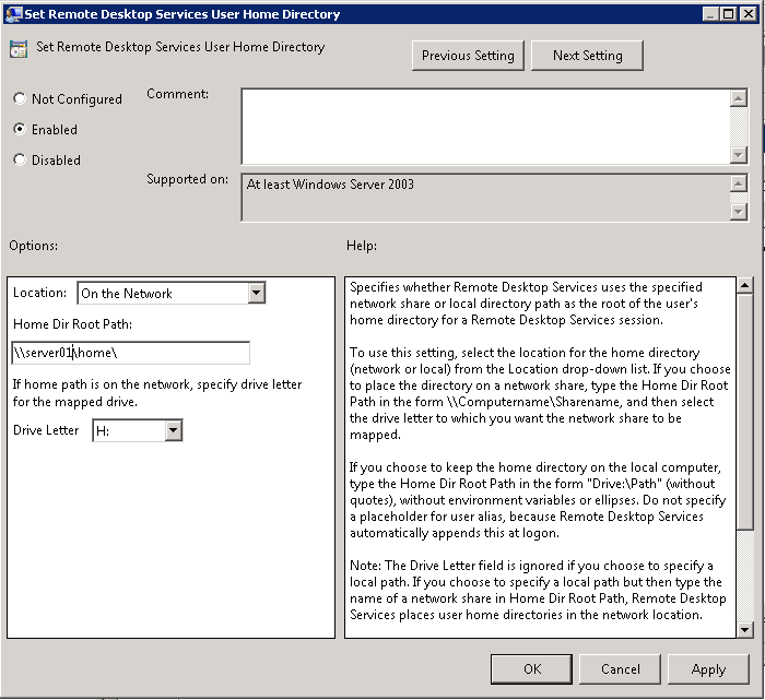
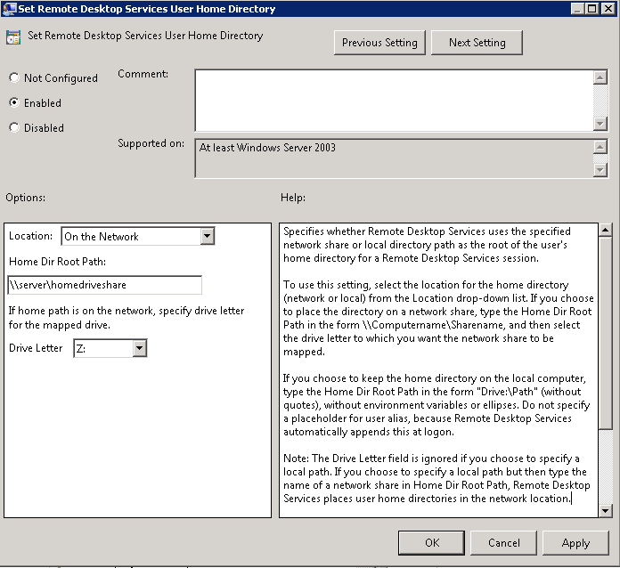
  • Set Remote Desktop Services User Home Directory

Navigate to Computer Configuration > Policies > Administrative Templates > Windows Components > Remote Desktop Services > Remote Desktop Session Host\Profiles

rdhome2

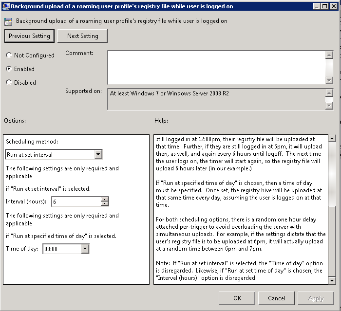
  • Background upload of a roaming profile’s registry while user is logged on

Navigate to Computer Configuration > Policies > Administrative Templates > System > User Profiles > Background upload of a roaming profile’s registry while user is logged on

sync

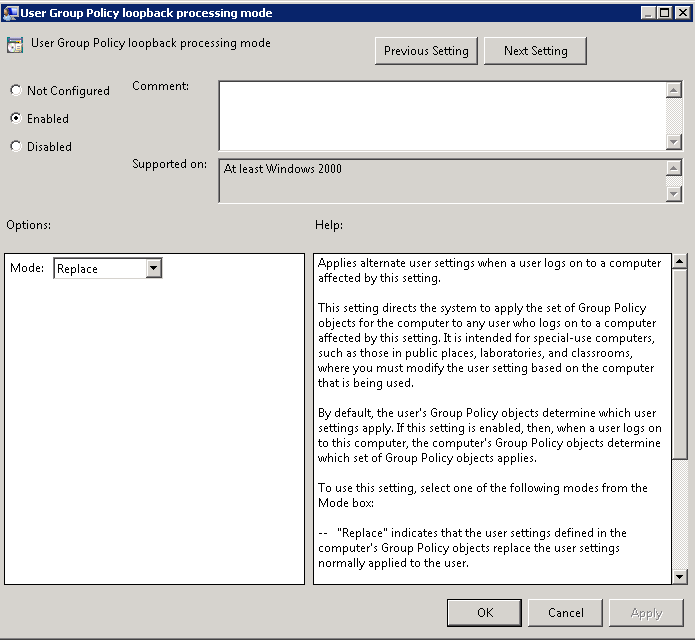
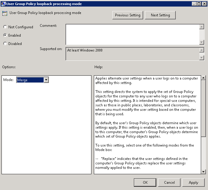
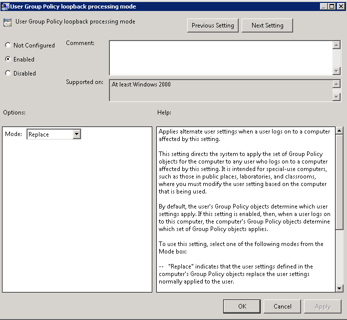
  • User Group Policy loopback processing mode

Navigate to: Computer Configuration > Policies > Admin Templates > System > Group Policy and change the following setting: User Group Policy loopback processing mode to Replace

loopback

Quotas

Quotas on Profile and Home Directories can be controlled to stop them growing large. Please see the following Blog post for details on setting this up

http://www.electricmonk.org.uk/?s=quota

Issues

  • If you set the Group Policy Computer Configuration > Administrative Templates > Windows Components > Remote Desktop Services > Remote Desktop Session Host > Profiles > Set Remote Desktop Services User Home Directory as per below

gpo

and

gpo2

  • You will get a folder mapped which is actually \\server\homedrive%username%.%domain%
  • The username only folder which is what you actually want when it is mapped not the username.domain folder is created just after the username.domain folder, this is actually when the redirection policy is running. The folder redirection is creating the username directory and you will see the redirected folders underneath this. If you try redirecting to %username%.%userdomain% it starts to mess redirection up.

What can you do?

  • You could live with the fact that your \\server\homedrive\%userame% folder is holding the redirected folders and
  • You could live with the fact that your \\server\homedrive%username%.%domain% folder is the offiical GPO created tshome folder
  • But you can not set this policy at all and simply leave it as unconfigured and set the home drive on the user’s AD Profile as per below
  • Then it setups correctly and you’ll see all your redirected folders in here as well.

gpo3


RAID Levels

mirror-from-IKEA

What is RAID?

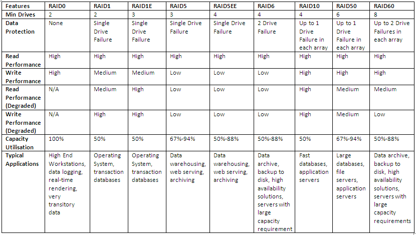
RAID stands for Redundant Array of Inexpensive (Independent) Disks. Data is distributed across the drives in one of several ways called “RAID levels”, depending on what level of redundancy and performance is required.

RAID Concepts

  • Striping
  • Mirroring
  • Parity or Error Correction
  • Hardware or Software RAID

RAID Levels

0,1,5 and 10 are the most commonly used RAID Levels

  • RAID 0

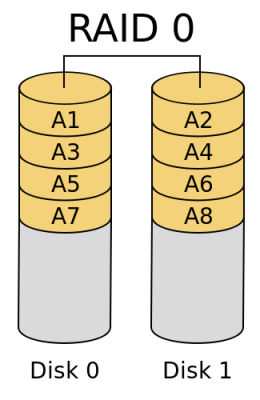
RAID_0.svg

RAID 0 (block-level striping without parity or mirroring) has no (or zero) redundancy. It provides improved performance and additional storage but no fault tolerance. Hence simple stripe sets are normally referred to as RAID 0. Any drive failure destroys the array, and the likelihood of failure increases with more drives in the array. A single drive failure destroys the entire array because when data is written to a RAID 0 volume, the data is broken into fragments called blocks. The number of blocks is dictated by the stripe size, which is a configuration parameter of the array. The blocks are written to their respective drives simultaneously on the same sector. This allows smaller sections of the entire chunk of data to be read off each drive in parallel, increasing bandwidth. RAID 0 does not implement error checking, so any read error is uncorrectable. More drives in the array means higher bandwidth, but greater risk of data loss.

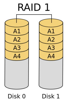
  • RAID 1

RAID_1.svg

In RAID 1 (mirroring without parity or striping), data is written identically to two drives, thereby producing a “mirrored set”; the read request is serviced by either of the two drives containing the requested data, whichever one involves least seek time plus rotational latency. Similarly, a write request updates the stripes of both drives. The write performance depends on the slower of the two writes (i.e., the one that involves larger seek time and rotational latency); at least two drives are required to constitute such an array. While more constituent drives may be employed, many implementations deal with a maximum of only two. The array continues to operate as long as at least one drive is functioning. With appropriate operating system support, there can be increased read performance as data can be read off any of the drives in the array, and only a minimal write performance reduction; implementing RAID 1 with a separate controller for each drive in order to perform simultaneous reads (and writes) is sometimes called “multiplexing” (or “duplexing” when there are only two drives)

When the workload is write intensive you want to use RAID 1 or RAID 1+0

  • RAID 5

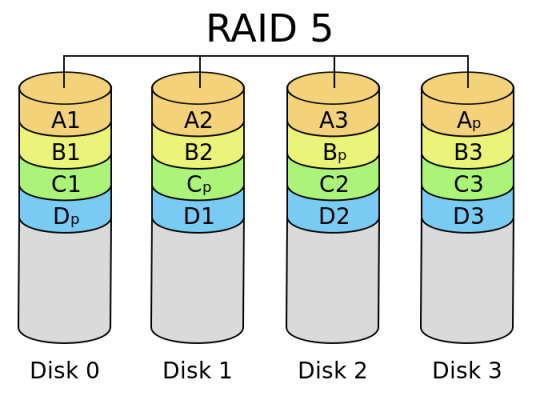
RAID_5.svg

RAID 5 (block-level striping with distributed parity) distributes parity along with the data and requires all drives but one to be present to operate; the array is not destroyed by a single drive failure. Upon drive failure, any subsequent reads can be calculated from the distributed parity such that the drive failure is masked from the end user. However, a single drive failure results in reduced performance of the entire array until the failed drive has been replaced and the associated data rebuilt, because each block of the failed disk needs to be reconstructed by reading all other disks i.e. the parity and other data blocks of a RAID stripe. RAID 5 requires at least three disks. Best cost effective option providing both performance and redundancy. Use this for DB that is heavily read oriented. Write operations will be dependent on the RAID Controller used due to the need to calculate the parity data and write it across all the disks

When your workloads are read intensive it is best to use RAID 5 or RAID 6 and especially for web servers where most of the transactions are read

Don’t use RAID 5 for heavy write environments such as Database servers

  • RAID 10 or 1+0 (Stripe of Mirrors)

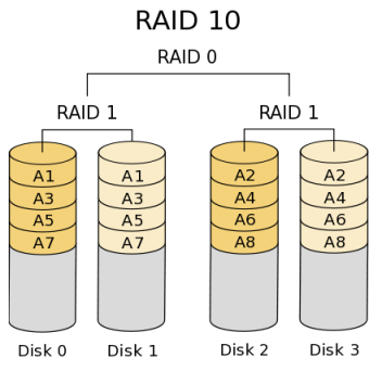
RAID_10

In RAID 10 (mirroring and striping), data is written in stripes across primary disks that have been mirrored to the secondary disks. A typical RAID 10 configuration consists of four drives, two for striping and two for mirroring. A RAID 10 configuration takes the best concepts of RAID 0 and RAID 1, and combines them to provide better performance along with the reliability of parity without actually having parity as with RAID 5 and RAID 6. RAID 10 is often referred to as RAID 1+0 (mirrored+striped) This is the recommended option for any mission critical applications (especially databases) and requires a minimum of 4 disks. Performance on both RAID 10 and RAID 01 will be the same.

  • RAID 01 (Mirror of Stripes)

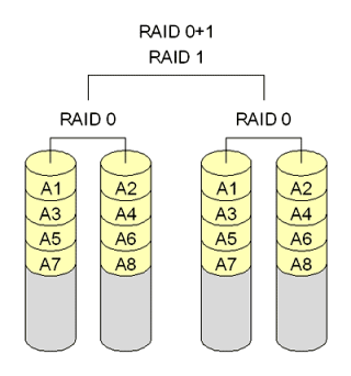
raid01

RAID 01 is also called as RAID 0+1. It requires a minimum of 3 disks. But in most cases this will be implemented as minimum of 4 disks. Imagine  two groups of 3 disks. For example, if you have total of 6 disks, create 2 groups. Group 1 has 3 disks and Group 2 has 3 disks.
Within the group, the data is striped. i.e In the Group 1 which contains three disks, the 1st block will be written to 1st disk, 2nd block to 2nd disk, and the 3rd block to 3rd disk. So, block A is written to Disk 1, block B to Disk 2, block C to Disk 3.
Across the group, the data is mirrored. i.e The Group 1 and Group 2 will look exactly the same. i.e Disk 1 is mirrored to Disk 4, Disk 2 to Disk 5, Disk 3 to Disk 6. This is why it is called “mirror of stripes”. i.e the disks within the groups are striped. But, the groups are mirrored. Performance on both RAID 10 and RAID 01 will be the same.

  • RAID 2

RAID2_arch.svg

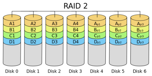
In RAID 2 (bit-level striping with dedicated Hamming-code parity), all disk spindle rotation is synchronized, and data is striped such that each sequential bit is on a different drive. Hamming-code parity is calculated across corresponding bits and stored on at least one parity drive. This theoretical RAID level is not used in practice. You need two groups of disks. One group of disks are used to write the data, another group is used to write the error correction codes. This is not used anymore. This is expensive and implementing it in a RAID controller is complex, and ECC is redundant now-a-days, as the hard disk themselves can do this themselves

  • RAID 3

RAID_3.svg

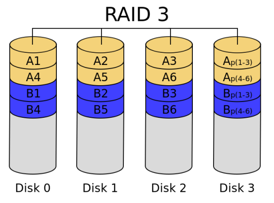
In RAID 3 (byte-level striping with dedicated parity), all disk spindle rotation is synchronized, and data is striped so each sequential byte is on a different drive. Parity is calculated across corresponding bytes and stored on a dedicated parity drive. Although implementations exist, RAID 3 is not commonly used in practice. Sequential read and write will have good performance. Random read and write will have worst performance.

  • RAID 4

675px-RAID_4.svg

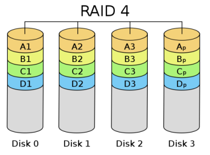
RAID 4 (block-level striping with dedicated parity) is identical to RAID 5 (see below), but confines all parity data to a single drive. In this setup, files may be distributed between multiple drives. Each drive operates independently, allowing I/O requests to be performed in parallel. However, the use of a dedicated parity drive could create a performance bottleneck; because the parity data must be written to a single, dedicated parity drive for each block of non-parity data, the overall write performance may depend a great deal on the performance of this parity drive.

  • RAID 6

RAID_6.svg

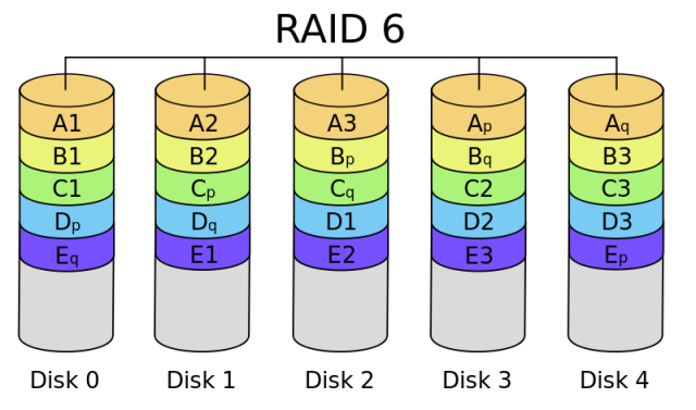
RAID 6 (block-level striping with double distributed parity) provides fault tolerance of two drive failures; the array continues to operate with up to two failed drives. This makes larger RAID groups more practical, especially for high-availability systems. This becomes increasingly important as large-capacity drives lengthen the time needed to recover from the failure of a single drive. Single-parity RAID levels are as vulnerable to data loss as a RAID 0 array until the failed drive is replaced and its data rebuilt; the larger the drive, the longer the rebuild takes. Double parity gives additional time to rebuild the array without the data being at risk if a single additional drive fails before the rebuild is complete. Like RAID 5, a single drive failure results in reduced performance of the entire array until the failed drive has been replaced and the associated data rebuilt.

Don’t use for high random write workloads

What is Parity?

Parity data is used by some RAID levels to achieve redundancy. If a drive in the array fails, remaining data on the other drives can be combined with the parity data (using the Boolean XOR function) to reconstruct the missing data.

For example, suppose two drives in a three-drive RAID 5 array contained the following data:

Drive 1: 01101101
Drive 2: 11010100

To calculate parity data for the two drives, an XOR is performed on their data:

01101101
XOR  11010100
_____________
10111001

The resulting parity data, 10111001, is then stored on Drive 3.

Should any of the three drives fail, the contents of the failed drive can be reconstructed on a replacement drive by subjecting the data from the remaining drives to the same XOR operation. If Drive 2 were to fail, its data could be rebuilt using the XOR results of the contents of the two remaining drives, Drive 1 and Drive 3:

Drive 1: 01101101
Drive 3: 10111001

as follows:

10111001
XOR  01101101
_____________
11010100

The result of that XOR calculation yields Drive 2’s contents. 11010100 is then stored on Drive 2, fully repairing the array. This same XOR concept applies similarly to larger arrays, using any number of disks. In the case of a RAID 3 array of 12 drives, 11 drives participate in the XOR calculation shown above and yield a value that is then stored on the dedicated parity drive.

RAID Level Comparison

RAID

Interesting Link

http://www.miracleas.com/BAARF/RAID5_versus_RAID10.txt


Adding the VMware Toobar to your browser

yeechat_help-20110110

For quick access to communities, documentation, downloads, support information and more, download the VMware Support Toolbar available on the link below

Link

http://vmwaresupport.toolbar.fm

TOOLBAR

Happy New Year 2013

Happy New Year to everyone and all the best for 2013

new-year-143a

Installing VMware vCenter Server 5.1 using the Simple Install method

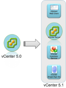
Architectural Changes

The vCenter Server 5.1 release includes significant architectural changes. You must understand these changes before attempting to freshly install or upgrade to vCenter Server 5.1 from older versions of the product. There are four separate services that constitute the vCenter Server 5.1 platform. These are below and must be installed in order

  • vCenter Single Sign On (SSO)
  • vCenter Inventory Service
  • vCenter Server
  • vSphere Web Client

Pre Requisites

Before installing vCenter Server 5.1, vSphere 5.1 requires you to install vCenter Single Sign On and install the Inventory Service. You can install vCenter Single Sign On, Inventory Service, and vCenter Server all on a single host machine using the vCenter Server Simple Install option. This option is appropriate for small deployments.

Alternatively, you can install vCenter Single Sign On, vCenter Inventory Service, and vCenter Server separately to customize the location and configuration of the components. (I found this to be the best way)

You also need Adobe Flash installed for the vSphere Web Client

If you are running vCenter as a Virtual Machine in Workstation then you will need at least 2GB RAM or more!

SSO-MultiSItesso-arch1

This blog will focus on installing vCenter Single Sign On, Inventory Service, and vCenter Server all on a single host machine running Windows Server 2008 R2 Enterprise

Instructions

Note: It may be best to install each component separately. I encountered a few errors when I went through the Simple Install Method. See screenprint below

Error

  • Download the ISO or installer from the VMware website
  • Make sure you have the .NET Framework installed
  • Attach the ISO or run the installer on your designated vCenter Server

vCenterInstaller

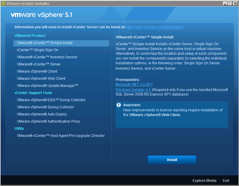
  • Select VMware vCenter Server Simple Install and Click Install

vcenter

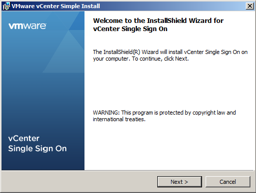
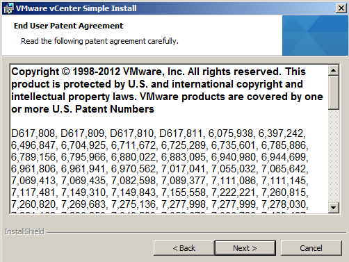
  • Click Next

vCenter0

  • Click Next

vCenter1

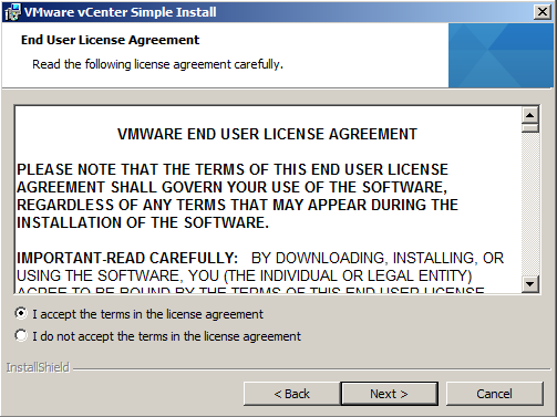
  • Select I accept the terms in the license agreement and click Next

vCenter2

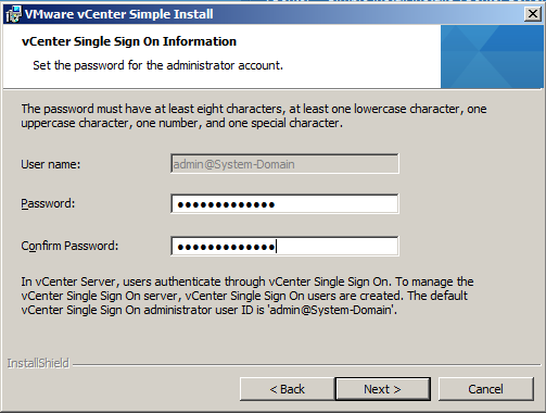
  • Put in a Strong Password and click Next. This is a local account not tied to AD or the Windows host. After SSO is installed, you can configure it for one or more LDAP/AD server and other identity sources.

Capture

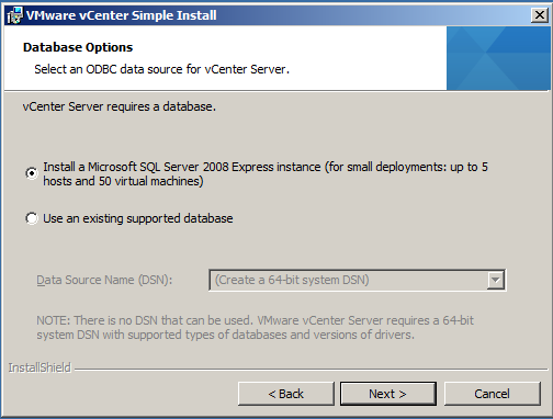
  • For this demo, we will just be using the Express Instance

vCenter4

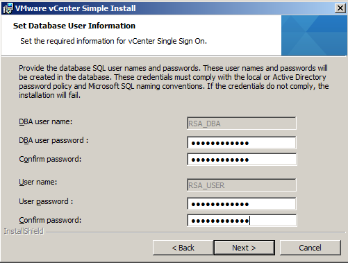
  • Put in the passwords for the RSA_USER and RSA_DBA accounts

vCenter5

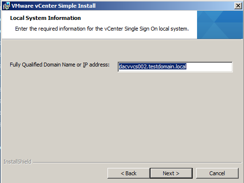
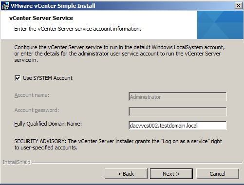
  • The FQDN should be in here automatically. If you get an error saying nslookup cannot perform a lookup against this address then check your DNS server

vCenter6

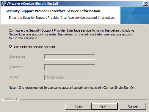
  • Use Network Service Account or put in a Username and Password
  • Click Next

Capture1

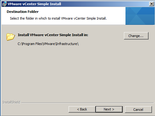
  • Choose the location to save into and click Next

Capture3

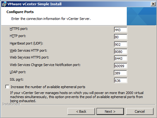
  • Check HTTP Port

Capture4

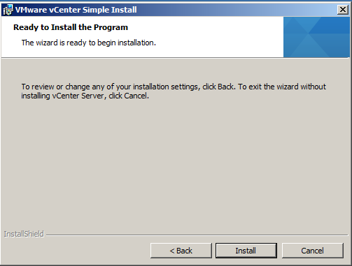
  •  Click Install and allow SQL DB to be installed and SSO
  • When this has finished you will get the screen below
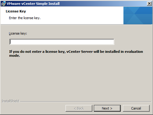
  • Put in a license key or just click Next if you are using it in Evaluation Mode

Capture

  • Click Next

Capture1

  • Click Next

Capture2

  • Click Next

Capture4

  • Click Next

Capture3

  • Click Next

Capture5

  • Click Install and then Finish
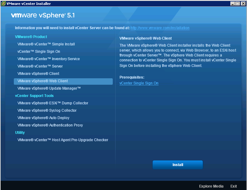
  • Install the vSphere 5 Web Client (Just follow the prompts)

Capture

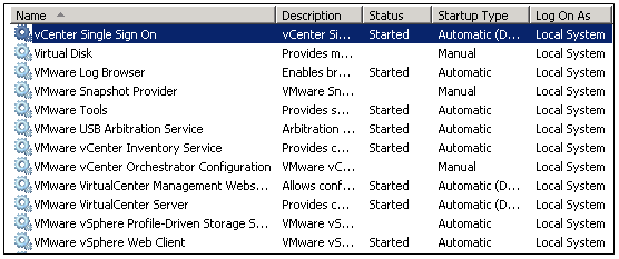
  • Next check all the vCenter and Webservices and SSO are running

service

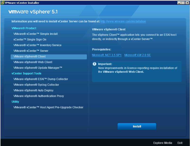
  • Install the vSphere 5 client

client5

  • Make sure you have downloaded and installed Adobe Flash
  • Just a quick point, make sure your vCenter Server has +2GB RAM or things just don’t work very well especially if you are running SSO, Inventory and vCenter on the same box as a test
  • You also may need to adjust your firewall for port 9443
  • If you are running 5.1 rather than 5.0, it is best to log into the vSphere Web Client first before on https://localhost:9443/vsphere-client/ using your SSO Login admin@System-Domain + inital setup password before logging into the vSphere Web Admin Assistant on https://localhost:9443/admin-app or you will get an error such as the below
The vSphere Web Client Administration Tool only supports registration of vCenter
 Server version 5.0.  For newer versions, the vCenter Server system must be regi
stered with the Lookup Service to allow the vSphere Web Client to discover the s
ystem.
  • Log into vSphere web client as admin (admin@System-Domain, this is the default user added during install of vcenter)
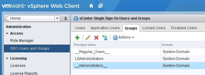
  • Go to Administration -> SSO Users and Groups
  • Go to Groups tab and click on __Administrators__
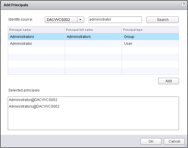
  • Click on the little man icon to Add Principals

Capture

  • Select the local vCenter server as the identity source and search for a local user. See Screenprint) you can add your Admins Group or any other group
  • Then add that user and click OK.
  • Log in as the local user.
  • You should see the vCenter listed after you log in, if not, you may need to reboot.

perms

Useful VMware KB for troubleshooting known certificate error

http://blogs.vmware.com/kb/2012/10/implementing-ca-signed-ssl-certificates-with-vsphere-5-1.html
SSO Issues (Cannot log in using Domain account to vClient etc)

http://blogs.vmware.com/kb/2012/10/vsphere-sso-resources.html
http://longwhiteclouds.com/2012/09/26/vsphere-5-1-gotcha-with-single-sign-on-sso/

  • Go to Administration
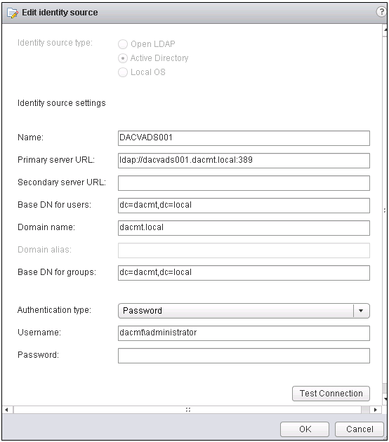
  • Single Sign On and Discovery > Configuration
  • Click the + sign to add a new identity source. E.g Active Directory Server.
  • Fill in as per your domain. Note my lab domain is dacmt.local
identity

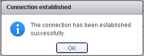
  • Click Test Connection
  • Wait for it to say Connection successful

connection good

  • Change the order of the domains so AD is at the top

Registering vCenter Server 5 (Not 5.1)

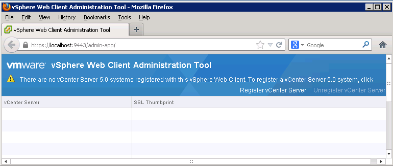
  • Log into the vSphere Web Admin Assistant on https://localhost:9443/admin-app

web

  • Click Register vCenter
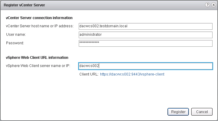
  • Enter the vCenter FQDN
  • Enter the Username and Password
  • Enter the vCenter hostname

vcenter

  • Click Register
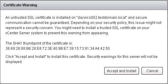
  • Accept the certificate

cert

Can you run vCenter 5 on Windows Servers 2012?

vCenter isn’t officially supported on Server 2012

What you will find is that the installation fails just before it tries to install the vSphere Profile-Driven Storage Service.

The reason why

To install that service, the vCenter service needs to be running. However, the vCenter service does not start properly in Windows Server 2012. This is due to a missing dependency. In particular, the VirtualCenter Server service relies on the ProtectedStorage service which was removed from Win8/Server 2012. The work around is the following open regedit and go to \System\CurrentControlSet\Services\vpxd and then open the DependOnService key and remove ProtectedStorage from the list. Reboot the machine and the vCenter service should come alive (might take a while). Then restart only the vCenter installation again once everything has come up (you need to wait for vCenter service to come alive which can take a few minutes). The install will continue from where it kicked off and finish

So the short version is, when the vCenter install fails, go to registry and remove ProtectedStorage dependency from the vpxd service, reboot and it should work. Restart the vcenter install and it will finish as per normal.

Should you delete files in the \WinSXS directory?

92736_340

Recently following a clear out of my Windows 7 64bit laptop and running TreeSize to locate offending large files and folders, I found a 6GB folder called WinSXS. Not having a clue about what this folder was, I decided to investigate..

First of all “Can I delete the \Windows\Winsxs directory?”

To answer the question, the answer is actually: No.

Why?

Because the component store (\Winsxs) is needed to repair the OS binaries in the event that a file becomes corrupted or, in worst case scenarios, compromised.  There are a few directories in the component store so let’s look at them and what their general role is in Windows. WinSxS folder replaces the old $NTUninstall folders from XP which is one of the reasons it grows after installing Updates

  1. \Winsxs\Catalogs:  Contains security catalogs for each manifest on the system
  2. \Winsxs\InstallTemp: Temporary location for install events
  3. \Winsxs\Manifests: Component manifest for a specific component, used during operations to make sure files end up where they should
  4. \Winsxs\Temp: Temp directory used for various operations, you’ll find pending renames here
  5. \Winsxs\Backup: Backups of the manifest files in case the copy in \Winsxs\Manifests becomes corrupted
  6. \Winsxs\Filemaps: File system mapping to a file location
  7. \Winsxs\<big_long_file_name>: The payload of the specific component, typically you will see the binaries here.

Explanation

The Windows component store (C:\Windows\winsxs) directory is used during servicing operations within Windows installations.  Servicing operations include, but are not limited to, Windows Update, Service Pack and hotfix installations.

The component store contains all of the files needed for a Windows installation and any updates to those files are also held within the component store as they are installed.  This will cause the component store to grow over time as more updates, features or roles are added to the installation.  The component store utilizes NTFS hard links between itself and other Windows directories to increase the robustness of the Windows platform.

The component store will show a large directory size due to the way the Windows Explorer shell accounts for hard links.  The Windows shell will count each reference to a hard link as a single instance of the file for each directory the file resides in. For example, if a file named advapi32.dll was 700 KB in size and was contained in the component store and the \Windows\system32 directory, Windows Explorer would inaccurately report that it consumes 1400 KB of hard disk space

The component store cannot reside on another volume other than the system volume due to the use of NTFS hard links.  Attempting to move the component store will result in the inability to properly install Windows updates, Service Packs, roles or features.  Additionally, it is not recommended that files be manually removed or deleted from the component store.

To reduce the size of the component store directory on a Windows installation you can choose to make the service pack installation permanent and reclaim used space from the Service Pack files.  Doing this will make the Service Pack permanent and it will not be removable.

To remove the Service Pack files from a Windows installation use the following in-box utilities:

  • Windows Vista Service Pack 1 installed: VSP1CLN.EXE
  • Windows Vista Service Pack 2 or Windows Server 2008 Service Pack 2 installed: Compcln.exe
  • Windows 7 Service Pack 1 or Windows Server 2008 R2 Service Pack 1 installed: DISM /online /Cleanup-Image /SpSuperseded or Disk Cleanup Wizard (cleanmgr.exe)

Scavenging may also be proactively performed on Windows Vista and Windows 2008 installations by forcing a removal event on the system.  Scavenging will attempt to remove any unneeded system binaries from the installation and allow Windows to reclaim the disk space.  To issue an uninstall event on a Windows installation, simply add and remove any unneeded system component that is not already installed and reboot the Windows installation.  Scavenging will be performed during the subsequent reboot of the operating system.

NOTE: Scavenging is performed automatically on Windows 7 and Windows 2008 R2 installation

TechNet Virtual Labs

BWatom

What are TechNet Virtual Labs?

TechNet Virtual Labs enable you to quickly evaluate and test Microsoft’s newest products and technologies through a series of guided, hands-on labs that you can complete in 90 minutes or less. There is no complex setup or installation required, and you can use TechNet Virtual Labs online immediately, free

What Labs are available?

  • Exchange Server
  • SQL Server 2012
  • SQL Server 2008 R2
  • Internet Information Services (IIS)
  • Windows Server 2008
  • Windows Server 2012
  • Windows Small Business Server
  • Windows Azure
  • Windows 7
  • Forefront Security
  • System Center
  • Microsoft Lync Server
  • Microsoft Office
  • Sharepoint

Link

http://technet.microsoft.com/en-us/virtuallabs/default.aspx

Server 2012 Labs

http://technet.microsoft.com/en-us/windowsserver/hh968267.aspx