What is DPM?
The vSphere Distributed Power Management (DPM) feature allows a DRS cluster to reduce its power consumption by powering hosts on and off based on cluster resource utilization.
vSphere DPM monitors the cumulative demand of all virtual machines in the cluster for memory and CPU resources and compares this to the total available resource capacity of all hosts in the cluster. If sufficient excess capacity is found, vSphere DPM places one or more hosts in standby mode and powers them off after migrating their virtual machines to other hosts. Conversely, when capacity is deemed to be inadequate, DRS brings hosts out of standby mode (powers them on) and uses vMotion to migrate virtual machines to them. When making these calculations, vSphere DPM considers not only current demand, but it also honors any user-specified virtual machine resource reservations.
ESXi hosts cannot automatically be brought out of standby mode unless they are running in a cluster managed by vCenter Server.
Power Management Protocols
vSphere DPM can use one of three power management protocols to bring a host out of standby mode:
- Intelligent Platform Management Interface (IPMI)
- Hewlett-Packard Integrated Lights-Out (iLO), or
- Wake-On-LAN (WOL)
Each protocol requires its own hardware support and configuration. If a host does not support any of these protocols it cannot be put into standby mode by vSphere DPM. If a host supports multiple protocols, they are used in the following order: IPMI, iLO, WOL.
Configure IPMI or iLO Settings for vSphere DPM (Host First)
IPMI is a hardware-level specification and Hewlett-Packard iLO is an embedded server management technology. Each of them describes and provides an interface for remotely monitoring and controlling computers.
You must perform the following procedure on each host.
Prerequisites
- Both IPMI and iLO require a hardware Baseboard Management Controller (BMC) to provide a gateway for accessing hardware control functions, and allow the interface to be accessed from a remote system using serial or LAN connections. The BMC is powered-on even when the host itself is powered-off. If properly enabled, the BMC can respond to remote power-on commands.
- If you plan to use IPMI or iLO as a wake protocol, you must configure the BMC. BMC configuration steps vary according to model. See your vendor’s documentation for more information.
- With IPMI, you must also ensure that the BMC LAN channel is configured to be always available and to allow operator-privileged commands.
- On some IPMI systems, when you enable “IPMI over LAN” you must configure this in the BIOS and specify a particular IPMI account.
- vSphere DPM using only IPMI supports MD5- and plaintext-based authentication, but MD2-based authentication is not supported. vCenter Server uses MD5 if a host’s BMC reports that it is supported and enabled for the Operator role. Otherwise, plaintext-based authentication is used if the BMC reports it is supported and enabled. If neither MD5 nor plaintext authentication is enabled, IPMI cannot be used with the host and vCenter Server attempts to use Wake-on-LAN.
Instructions to Configure BMC from UEFI
(Alternatively, you may configure IPMI by pressing Ctrl + E during boot)
During these steps, remember to record the IP address and MAC address of the BMC.
- Power on the host
- Enter the Unified Server Configurator (UEFI v2.1) by pressing F10 (System Services) at boot
- After the application start, select Configuration Wizards
- Select iDRAC Configuration
- Enable IPMI Over LAN, click Next
- Enter a Host Name String that aligns with the ESXi host name, click Next
- Enter a unique IP Address and the details of your network, click Next
- Optionally configure IP6, click Next
- Click Next at the Virtual Media Configuration screen
- At the LAN User Configuration screen, we configured an account and password, click Next
- At the summary screen, click Apply
- Click Finish, Back, Exit and Reboot
Configure Wake On LAN
- Power on the host
- Press Ctrl + S to Enter Broadcom Comprehensive Configuration Management
- Select the adapter to be used for WOL
- Select MBA Configuration
- Enable Pre-boot Wake On LAN
- Press Escape, Escape, Save and Exit
- Repeat steps 3 – 6 for any other adapters
- Press Escape
Configure IPMI/iLO for vSphere 5
Note: This may only be done from a connection to vCenter. This is a feature that relies upon DRS.
- Press Ctrl + Shift + H to enter the Host and Cluster View from within vSphere Client
- Select the Host to enable IPMI/iLO (You should configure IPMI/iLO on all hosts in your cluster)
3.Click the Configuration Tab > Software > Power Management
4.Click Properties
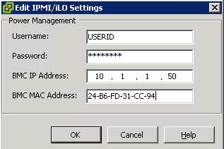
5.Enter the Username, Password, IP Address, and MAC Address
- First you may need to log into IPMI, ILO or WOL and obtain the IP and MAC Address
- Log into vCenter
- Select a host
- Select Configuration
- Select Power Management
- Click Properties
- Enter the following information.
- User name and password for a BMC account. (The user name must have the ability to remotely power the host on.)
- IP address of the NIC associated with the BMC, as distinct from the IP address of the host. The IP address should be static or a DHCP address with infinite lease.
- MAC address of the NIC associated with the BMC.
Configure Wake on LAN Settings for vSphere DPM (Host First)
The use of Wake-on-LAN (WOL) for the vSphere DPM feature is fully supported, if you configure and successfully test it according to the VMware guidelines. You must perform these steps before enabling vSphere DPM for a cluster for the first time or on any host that is being added to a cluster that is using vSphere DPM.
Prerequisites
Before testing WOL, ensure that your cluster meets the prerequisites.
- Your cluster must contain at least two ESX 3.5 (or ESX 3i version 3.5) or later hosts.
- Each host’s vMotion networking link must be working correctly. The vMotion network should also be a single IP subnet, not multiple subnets separated by routers
- The vMotion NIC on each host must support WOL. To check for WOL support, first determine the name of the physical network adapter corresponding to the VMkernel port by selecting the host in the inventory panel of the vSphere Client, selecting the Configuration tab, and clicking Network Adapters

- The Wake On LAN Supported column for the relevant adapter should show Yes.
- To display the WOL-compatibility status for each NIC on a host, select the host in the inventory panel o the vSphere Client, select the Configuration tab, and click Network Adapters. The NIC must show Yes in the Wake On LAN Supported column.
- The switch port that each WOL-supporting vMotion NIC is plugged into should be set to auto negotiate the link speed, and not set to a fixed speed (for example, 1000 Mb/s). Many NICs support WOL only if they can switch to 100 Mb/s or less when the host is powered off.
- After you verify these prerequisites, test each ESXi host that is going to use WOL to support vSphere DPM.
- When you test these hosts, ensure that the vSphere DPM feature is disabled for the cluster
- CAUTION Ensure that any host being added to a vSphere DPM cluster that uses WOL as a wake protocol is tested and disabled from using power management if it fails the testing. If this is not done, vSphere DPM might power off hosts that it subsequently cannot power back up.
Procedure
- Click the Enter Standby Mode command on the host’s Summary tab in the vSphere Client.
- This action powers down the host.
- Try to bring the host out of standby mode by clicking the Power On command on the host’s Summary tab.
- Observe whether or not the host successfully powers back on.
- For any host that fails to exit standby mode successfully, select the host in the cluster Settings dialog box’s Host Options page and change its Power Management setting to Disabled.
- After you do this, vSphere DPM does not consider that host a candidate for being powered off.
Enabling vSphere DPM for a DRS Cluster
After you have performed configuration or testing steps required by the wake protocol you are using on each host, you can enable vSphere DPM.
Configure the power management automation level, threshold, and host-level overrides. These settings are configured under Power Management in the cluster’s Settings dialog box.
If a host in your DRS cluster has USB devices connected, disable DPM for that host. Otherwise, DPM might turn off the host and sever the connection between the device and the virtual machine that was using it.
Instructions
- Right click the cluster and select Edit Settings
- Select Power Management
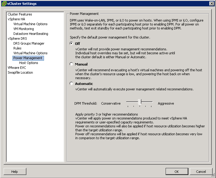
- These priority ratings are based on the amount of over- or under-utilization found in the DRS cluster and the improvement that is expected from the intended host power state change. A priority-one recommendation is mandatory, while a priority-five recommendation brings only slight improvement.
- The DRS threshold and the vSphere DPM threshold are essentially independent. You can differentiate the aggressiveness of the migration and host-power-state recommendations they respectively provide
Host-Level Overrides
When you enable vSphere DPM in a DRS cluster, by default all hosts in the cluster inherit its vSphere DPM automation level.
You can override this default for an individual host by selecting the Host Options page of the cluster’s Settings dialog box and clicking its Power Management setting. You can change this setting to the following options:
- Disabled
- Manual
- Automatic
NOTE: Do not change a host’s Power Management setting if it has been set to Disabled due to failed exit standby mode testing.
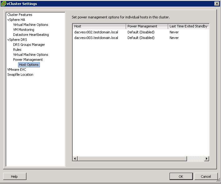
- After enabling and running vSphere DPM, you can verify that it is functioning properly by viewing each host’s Last Time Exited Standby information displayed on the Host Options page in the cluster Settings dialog box and on the Hosts tab for each cluster. This field shows a timestamp and whether vCenter Server Succeeded or Failed the last time it attempted to bring the host out of standby mode. If no such attempt has been made, the field displays Never.
NOTE: Times for the Last Time Exited Standby text box are derived from the vCenter Server event log. If this log is cleared, the times are reset to Never.
Power Management Techniques
After VMware DPM has determined the number of hosts needed to handle the load and to satisfy all relevant constraints and VMware DRS has distributed virtual machines across the hosts in keeping with resource allocation constraints and objectives, each individual powered-on host is free to handle power management of its hardware. For CPU power management, ESX 3.5 and 4 place idle CPUs in C1 halt state. ESX 4 also has support for host-level power-saving mechanisms through changing ACPI P-states; also known as dynamic voltage and frequency scaling (DVFS). DVFS runs CPUs at a lower speed and possibly at a lower voltage when there is sufficient excess capacity where the workload will not be affected. DVFS is “off” by default but can be turned on by setting the Power.CpuPolicy advanced option to “dynamic” for the hardware that supports it. Host-level power management is synergistic with VMware DPM. Even though it can provide additional power savings beyond VMware DPM, it cannot save as much power as VMware DPM does by powering hosts down completely.
vSphere DPM Powers off the host when the cluster load is low
- DPM considers a 40 minute load history
- Migrates all VMs to other hosts
vSphere DPM powers on the host when the cluster load is high
- DPM considers a 5 minute load history
- Wake up packets are sent to the host which boots up
- DRS initiates and some VMs are migrated to this host
VMware DPM Operation
The goal of VMware DPM is to keep the utilization of ESX hosts in the cluster within a target range, subject to the constraints specified by the VMware DPM operating parameters and those associated with VMware HA and VMware DRS. VMware DPM evaluates recommending host power-on operations when there are hosts whose utilization is above this range and host power-off operations when there are hosts whose utilization is below it. Although this approach might seem relatively straightforward, there are key challenges that VMware DPM must overcome to be an effective power-saving solution. These include the following:
- Accurately assess workload resource demands. Overestimating can lead to less than ideal power savings. Underestimating can result in poor performance and violations of VMware DRS resource-level SLAs.
- Avoid powering servers on and off frequently, even if running workloads are highly variable. Powering servers on and off too often impairs performance because it requires superfluous VMotion operations.
- React rapidly to sudden increase in workload demands so that performance is not sacrificed when saving power.
- Select the appropriate hosts to power on or off. Powering off a larger host with numerous virtual machines might violate the target utilization range on one or more smaller hosts.
• Redistribute virtual machines intelligently after hosts are powered on and off by seamlessly leveraging VMware DRS.
VMware DPM is run as part of the periodic VMware DRS invocation (every five minutes by default), immediately after the core VMware DRS cluster analysis and rebalancing step is complete. VMware DRS itself may recommend host power-on operations, if the additional capacity is needed as a prerequisite for migration recommendations to honor VMware HA or VMware DRS constraints, to handle user requests involving host evacuation (such as maintenance mode), or to place newly powered-on virtual machines.
Evaluating Utilization
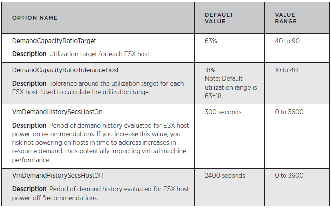
VMware DPM evaluates the CPU and memory resource utilization of each ESX host and aims to keep the host’s resource utilization within a target utilization range. VMware DPM may take appropriate action when the host’s utilization falls outside the target range. The target utilization range is defined as:
Target resource utilization range = DemandCapacityRatioTarget ± DemandCapacityRatioToleranceHost
By default, the utilization range is 45% to 81% (that is, 63% ±18%)
Each ESX host’s resource utilization is calculated as demand/capacity for each resource (CPU and memory). In this calculation, demand is the total amount of the resource needed by the virtual machines currently running on the ESX host and capacity is the total amount of the resource currently available on the ESX host. A virtual machine’s demand includes both its actual usage and an estimate of its unsatisfied demand, to account for cases in which the demand value is constrained by the ESX host’s available resources. If an ESX host faces heavy contention for its resources, its demand can exceed 100 percent. VMware DPM computes actual memory usage using a statistical sampling estimate of the virtual machine’s working set size. It also computes the estimate of unsatisfied demand for memory using a heuristic technique.
VMware DPM calculates an ESX host’s resource demand as the aggregate demand over all the virtual machines running on that host. It calculates a virtual machine’s demand as its average demand over a historical period of time plus two standard deviations (capped at the virtual machine’s maximum demand observed over that period). Using a virtual machine’s average demand over a period of time, rather than simply its current demand, is intended to ensure that the demand used in the calculation is not anomalous. This approach also smoothes out any intermediate demand spikes that might lead to powering hosts on and off too frequently. The default period of time VMware DPM evaluates when it calculates average demand that may lead to host power-on recommendations is the past 300 seconds (five minutes). When it calculates average demand for host power-off recommendations, the default period of time VMware DPM evaluates is the past 2400 seconds (40 minutes). The default time period for evaluating host power-on recommendations is shorter because rapid reactions to power on hosts are considered more important than rapid reactions to power off hosts. In other words, providing the necessary resources for workload demands has a higher priority than saving power.
If any host’s CPU or memory resource utilization during the period evaluated for host power-on recommendations is above the target utilization range, VMware DPM evaluates powering hosts on. If any host’s CPU and any host’s memory resource utilization over the period evaluated for host power-off recommendations is below the target utilization range and there are no recommendations to power hosts on, VMware DPM evaluates powering hosts off.
In addition, when VMware DPM runs VMware DRS in what-if mode to evaluate the impact of host power-on and power-off, CPU and memory reservations are taken into account (as well as all other cluster constraints). VMware DRS will reject proposed host power-off recommendations that will violate reservations and VMware DRS will initiate host power-on operations to satisfy reservations.
Useful Link
http://www.vmware.com/files/pdf/Distributed-Power-Management-vSphere.pdf

