Memory Overcommitment and Java Applications

java

How can we monitor Java Applications on Virtualised Systems?

We can’t determine all we need to know about a Java workload from system tools such as System Monitor. We need to use specialized Java monitoring tools such as the below tools which helps us see inside the Java Heap, Garbage Collection, and other relevant Java metrics.

  • JConsole
  • vCenter Operations Suite

What is the Java Heap?

The Java Heap is used to store objects that the program is working on. For example, an object could be a customer record, a file or anything else the program has to manipulate. As objects are created, used and discarded by the program, you will see the Heap memory size change. Discarded objects (referred to as dead objects) are not immediately removed from the heap when the program is done with them. Instead, a special task called Garbage Collection, runs through the heap to detect dead objects. Once it detects a dead object, it deletes the object and frees up the memory.

The Java Heap is divided in to pools of memory, referred to as generations. There are three generations called

  • Eden Space
  • Survivor Space
  • Tenured Gen

This helps the Garbage collection (GC) process become more efficient by reducing the amount of memory it has to scan each time a GC is run. GC is run on the ‘Eden Space’ more often as this is where new objects are stored. GC runs less often on the Survivor space and even less often on the Tenured Gen space. If an object survives one GC run in the Eden Space, it is moved to the Survivor Space. If an object exists in the Survivor Space for some time, it is moved to the Tenured Gen.

Memory Reclamation Techniques

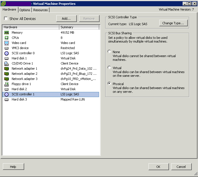
When running Java workloads on in an x86 Virtual Machine (i.e. a VM in the VMware sense of the word), it is recommended that you do not overcommit memory because the JVM memory is an active space where objects are constantly being created and garbage collected. Such an active memory space requires its memory to be available all the time. If you overcommit memory, memory reclamation techniques such as compression, ballooning or swapping may occur and impede performance

  • Memory compression involves compressing pages of memory (zipping) and storing them compressed instead of in native format. It has a performance impact because resources are used to compress and uncompress memory as it is being accessed. The host attempts to only compress inactive memory pages if at all possible. As GC runs through the java heap, it accesses lots of memory that may behave been marked as inactive. This causes any memory that has been compressed to decompress using up further VM resources.
  • Ballooning employs the memory balloon driver (vmmemctl), which is part of the VMware Tools package. This is loaded into the guest operating system on boot. When memory resources on the host become scarce (contended), the host tells the balloon driver to request memory (inflate) up to a target size (balloon target). The target is based on the amount of inactive memory the host believes the guest is holding on to. The memory balloon driver starts to request memory from the guest OS to force the guest to clean up inactive memory. Once the balloon driver has been allocated memory by the guest OS, it releases this back to other VMs by telling the Hypervisor that the memory is available. Once again, what appears to be inactive memory to the host may soon be subject to garbage collection, and become active again. If the guest has no inactive memory to release, it starts paging memory to disk in response to the request for memory from the balloon driver. This has a very negative impact on java performance
  • Swapping. This is a last resort memory reclamation technique that no application wants to be faced with. A serious decline in performance is likely with swapping

Best Practices

  • Enterprise Java Applications on VMware Best Practice Guide, which says you should not exceed 80% CPU utilization on the ESX host.
  • Reserving memory at the VM level is in general not a good idea, but essential for Java workloads due to the highly active java memory heap space. However, creating a memory reservation is a manual intervention step that we should try to avoid. Consider the situation in a large, dynamic, automated self-service environment (i.e. Cloud). Also, if we’re reserving memory for peak workloads within our java applications, we’re wasting resources as our applications don’t run at peak workload all the time. It would be good if the Java VM would just talk to the vSphere VM to let it know what memory is active, and what memory is idle so that vSphere could manage memory better, and the administrator could consolidate Java workloads without the fear of memory contention, or reserving memory for peak times.
  • Introducing VMware vFabric Elastic Memory for Java (EM4J). With EM4J, the traditional memory balloon driver is replaced with the EM4J balloon driver. The EM4J memory balloon sits directly in the Java heap and works with new memory reclamation capabilities introduced in ESXi 5.0. EM4J works with the hypervisor to communicate system-wide memory pressure directly into the Java heap, forcing Java to clean up proactively and return memory at the most appropriate times—when it is least active. You no longer have to be so conservative with your heap sizing because unused heap memory is no longer wasted on uncollected garbage objects. And you no longer have to give Java 100% of the memory that it needs; EM4J ensures that memory is used more efficiently, without risking sudden and unpredictable performance problems.

vFabric Elastic Memory for Java (EM4J)

vFabric Elastic Memory for Java (EM4J) is a set of technologies that helps optimize memory utilization for ESXi virtual machines running Java workloads.

EM4J provides vSphere administrators with the following tools:

  • The EM4J plug-in for the vSphere Web Client, together with the EM4J Console Guest Collector, provides a detailed, historical view of virtual machine and JVM memory usage, which helps vSphere administrators size the VM and Java heap memory optimally.
  • The EM4J agent establishes a memory balloon in the Java heap, which helps maintain predictable Java application performance when host memory becomes scarce. The balloon works with the ESXi hypervisor to reclaim memory from the Java heap when other VMs need memory.
  • The EM4J plug-in and the EM4J agent can be used together or independently.

For more information about EM4J, see vFabric Elastic Memory for Java Documentation at the link below

http://www.vmware.com/support/pubs/vfabric-em4j.html


Using VMware PowerCLI to manage VMware vSphere Update Manager Tasks

index

Requirements

  • PowerCLI 4.1 or higher
  • Update Manager PowerCLI Plugin
  • .NET 2.0 SP1
  • Windows PowerShell 2.0/3.0

Procedure

Install Update Manager PowerCLI

  1. Download the Update Manager PowerCLI plugin (You will need to login)
  2. https://my.vmware.com/group/vmware/get-download?downloadGroup=VUM51PCLI
  3. Navigate to the directory containing the Update Manager PowerCLI installation files.
  4. Run VMware-UpdateManager-Pscli-5.0.0-432001. Note that the version may be different for your installation.
  5. If prompted with a User Access Control warning, click Yes.
  6. On the Welcome screen, click Next.
  7. Accept the License Agreement, click Next.
  8. Click Install.
  9. Click Finish once the installation completes.
  10. Open the vSphere PowerCLI console from the Windows Start menu or by clicking the vSphere PowerCLI shortcut icon.
  11. Type Connect-VIServer
  12. Ignore the yellow certificate warnings or you can type the command to ignore them
  13. Type Get-Command -PSSnapin VMware.VumAutomation to get all the commands associated with this pssnapin

powercli

To create Patch Baselines

updatemanager

Attaching and Detaching Baselines

2

Scanning a Virtual Machine

3

To verify whether a virtual machine has at least one baseline with Unknown compliance status attached to it and start a scan

4

Staging Patches

Staging can be performed only for hosts, clusters, and datacenters.

5

Remediating Inventory Objects

You can remediate virtual machines, virtual appliances, clusters, and hosts.

6

Downloading Patches and Scanning Objects

7

VMware Link

http://pubs.vmware.com/vsphere-50/topic/com.vmware.ICbase/PDF/vsphere-update-manager-powercli-50-inst-admg.pdf

Quest ActiveRoles Management Shell for Active Directory

untitled

Quest ActiveRoles Management Shell for Active Directory

The ActiveRoles Management Shell for Active Directory is a set of predefined commands for Windows PowerShell, the new command line and scripting language developed by Microsoft. These commands are designed to help administrators automate common, repetitive and bulk management tasks such as creating, removing or updating objects in Active Directory.
By using the ActiveRoles Management Shell for Active Directory to build your scripts, you can harness Quest ActiveRoles Server to leverage proven rules, roles, workflow and attestation features giving you a robust management option for Windows PowerShell and Active Directory.

The management operations are performed either via the Quest ActiveRoles Server proxy service or by directly accessing directory data on domain controllers. In both cases, the ActiveRoles Management Shell provides a flexible scripting platform that can reduce the complexity of current Microsoft Visual Basic scripts. Tasks that previously required many lines in Visual Basic scripts can now be done by using as little as one line of code in the ActiveRoles Management Shell.

Installing the ActiveRoles Management Shell

q1

q2

q3

q4

q5

Opening the ActiveRoles Management Shell

You can open the ActiveRoles Management Shell by using either of the
following procedures. Each procedure loads the ActiveRoles Management Shell
snap-in into Windows PowerShell. If you do not load the ActiveRoles
Management Shell snap-in before you run a command (cmdlet) provided by
that snap-in, you will receive an error.

To open the ActiveRoles Management Shell from the Programs menu

  • Select Start | All Programs | Quest Software | ActiveRoles Management Shell for Active Directory.

To add the ActiveRoles Management Shell snap-in from Windows
PowerShell

  • Select Start | All Programs | Windows PowerShell 1.0 | Windows PowerShell.
  • At the Windows PowerShell prompt, enter the following command:
  • Add-PSSnapin Quest.ActiveRoles.ADManagement

Using the ActiveRoles Management Shell

  • Select Start | All Programs | Quest Software | ActiveRoles Management Shell for Active Directory.

q0

Admin Guide

Quest ActiveRoles Management Shell Admin Guide

Example Command to check for inactive users in Active Directory

get-qaduser -SizeLimit 0 | Where-Object{$_.LastLogon -lt $limit -OR $lastLogon -ne $null} | Sort-Object LastLogon | Select-Object Name, SAMAccountName, LastLogon | Export-CSV C:\PATH\TO\file.csv


Understand appropriate use cases for CPU affinity

magnet

What is CPU Affinity?

By specifying a CPU affinity setting for each virtual machine, you can restrict the assignment of virtual machines to a subset of the available processors in multiprocessor systems. By using this feature, you can assign each virtual machine to processors in the specified affinity set.

CPU affinity specifies virtual machine-to-processor placement constraints and is different from the relationship created by a VM-VM or VM-Host affinity rule, which specifies virtual machine-to-virtual machine host placement constraints.
In this context, the term CPU refers to a logical processor on a hyperthreaded system and refers to a core on a non-hyperthreaded system.

The CPU affinity setting for a virtual machine applies to all of the virtual CPUs associated with the virtual machine and to all other threads (also known as worlds) associated with the virtual machine. Such virtual machine threads perform processing required for emulating mouse, keyboard, screen, CD-ROM, and miscellaneous legacy devices.

By setting a CPU affinity on the virtual machine you are limiting the available CPUs on which the virtual machine can run. It does not dedicate that CPU to that virtual machine and therefore does not restrict the CPU scheduler from using that CPU for other virtual machines

Problems with CPU Affinity

In some cases, such as display-intensive workloads, significant communication might occur between the virtual CPUs and these other virtual machine threads. Performance might degrade if the virtual machine’s affinity setting prevents these additional threads from being scheduled concurrently with the virtual machine’s virtual CPUs. Examples of this include a uniprocessor virtual machine with affinity to a single CPU or a two-way SMP virtual machine with affinity to only two CPUs.

Consider your resource management needs before you enable CPU affinity on hosts using hyperthreading. For example, if you bind a high priority virtual machine to CPU 0 and another high priority virtual machine to CPU 1, the two virtual machines have to share the same physical core. In this case, it can be impossible to meet the resource demands of these virtual machines. Ensure that any custom affinity settings make sense for a hyperthreaded system

For the best performance

When you use manual affinity settings, VMware recommends that you include at
least one additional physical CPU in the affinity setting to allow at least one of the virtual machine’s threads to be scheduled at the same time as its virtual CPUs. Examples of this include

  • A uniprocessor virtual machine with affinity to at least two CPUs
  • A two-way SMP virtual machine with affinity to at least three CPUs

Assign a Virtual Machine to a Specific Processor
Using CPU affinity, you can assign a virtual machine to a specific processor. This allows you to restrict the assignment of virtual machines to a specific available processor in multiprocessor systems.

Procedure

  • In the vSphere Client inventory panel, select a virtual machine and select Edit Settings.
  • Select the Resources tab and select Advanced CPU
  • Click the Run on processor(s) button
  • Select the processors where you want the virtual machine to run and click OK
  • If you cannot see this option, it is because the host is in a DRS Cluster, the CPU affinity “Run on processor” feature  is not availble as its the DRS that manages ressources!

affinity

Use cases for CPU Affinity

  • Cisco’s Unity

Cisco Unity messaging is a real-time application, which makes it more difficult to virtualize than traditional data-centric applications, such as database and email servers. (For example, to support 144 concurrent voice sessions, Cisco Unity messaging must place 7,200 packets on the wire at a precise 20 ms interval.) Delivering this level of performance in a reliable, predictable, and serviceable manner requires some concessions, primarily surrounding CPU Affinity

Read this article on CPU Affinity

http://frankdenneman.nl/2011/01/11/beating-a-dead-horse-using-cpu-affinity/

Installing ESXi 5.1 as a VM on an ESXi 5.1 Host

images

Installing ESXi 5.1 as VM on an ESXi 5.1 Host

This article explains how to install VMware ESXi in a virtual machine. Installing ESXi in a virtual machine provides a way to try the product without dedicating hardware to it. A virtual ESXi machine may be useful if you are studying to become a VCP (VMware Certified Professional)

Nested Virtualisation Check

A quick way to verify whether your CPU truly supports both Intel-VT+EPT or AMD-V+RVI, you can paste the following into a browser:

https://[your-esxi-host-ip-address]/mob/?moid=ha-host&doPath=capability

You will need to login with your root credentials and then look for the “nestedHVSupported” property and if it states false, it means you maybe able to install nested ESXi or other hypervisor, but you will not be able to run nested 64-bit VMs, only 32-bit VMs, assuming you have either Intel-VT or AMD-V support on your CPUs.

Capture

  • Intel VT-x or AMD-V is required for running “Nested Virtualization” which supports nested 32-bit VMs
  • Intel EPT or AMD RVI is required for running nested 64-bit VMs

Instructions

  • Download the ESXi 5.1 ISO image from the VMware Download site
  • Log into your physical host with the vClient
  • Click on your Physical Host
  • Select Create Virtual Machine
  • Select Custom
  • Type a name for your Virtual ESXI 5.1 Host
  • Choose a Datastore
  • Select Virtual Machine Version 8
  • Choose Linux > Red Hat Enterprise Linux 6 (64bit)
  • Choose 2 Virtual Sockets and 1 core per virtual socket
  • Choose 2 or 4GB RAM
  • Choose your network
  • Choose your SCSI Controller. LSI Logic SAS is probably the best one to choose
  • Select a Create a new Virtual Disk
  • Select Disk size.
  • Choose your Disk Provisioning Method. Thick Provisioned Lazy Zero is ok
  • Select Store with the Virtual Machine
  • Choose Advanced Options. These can probably be left as they are
  • Next > Finish
  • When the VM is built, click Edit Settings
  • Attach your VMware ESXi 5.1 ISO to the VMs CD Drive and select to Connect at Power On
  • This next option is critical to allow a virtual machine to power on within the virtualized ESXi system. The advanced option “monitor_control.restrict_backdoor” with a value of “True” must be added to the virtual machine’s general options. The configuration parameters section is empty on the virtual machine at this point because it has not been created yet. If you have ever been in this section of the virtual machine configuration for a virtual machine that already exists, there are a number of options that are populated.
  • If you are using an i3 or later processor (that is, you do not have a Core 2 Duo), you can enable nested VT. This allows you to run 64bit virtual machines within ESXi. To enable nested VT, add this line – vhv.enable = “TRUE” to the .vmx file of the ESXi virtual machine:
  • Start the VM
  • Press Enter to start the boot process
  • Press fn+F11 to accept the EULA and continue
  • Select the virtual drive where you want to install. Press Enter to continue
  • Select a keyboard layout. Press Enter to continue.
  • Enter a root password. Press the down arrow key, then enter the password again to confirm. Press Enter to continue
  • This warning appears: <HARDWARE_VIRTUALIZATION WARNING: Hardware Virtualization is not a feature of the CPU, or is not enabled in the BIOS> This is generally expected. Press Enter to carry on
  • Confirm that the info on the screen is correct then press F11 to install
  • Reboot when required and remove the attached ISO
  • If virtual machines on the virtual ESXi server are going to be powered on, the Enable Promiscuous Mode option will need to be enabled on the vSwitch on which the virtual ESXi server resides.
  • The ESXi guest starts with an IP address assigned from DHCP. To set a static IP address: Press fn+F2.
  • Enter your password, then press Enter.
  • Select Configure Management Network, then press Enter.
  • Select IP Configuration, then press Enter.
  • Select Set static IP addresses and network configuration, then press the space bar.
  • Press the down arrow key to select IP Address field, then enter the correct information.
  • If you need to set the Subnet or Default Gateway, press the down arrow key to select those fields.
  • After you have finished adjusting the settings, press Enter to exit.
  • Press ESC to exit the configuration screen.
  • When you are prompted to restart the management network for the changes to take effect, press Y.
  • Press ESC again to go back to the main screen.

Running Hyper V

  • Edit your Virtual Switch and enable Promiscuous Mode
  • Upgrade your Hyper V VM to Hardware Version 9
  • Use WinSCP to tweak the hyperv.vmx file
  • guestOS = “winhyperV”
  • featMask.vm.hv.capable = “Min:1” followed by a carriage return
  • Save Changes

Configure an Auto Deploy Reference Host

Cloud

Introduction

In an environment where no state is stored on the host, a reference host helps you set up multiple hosts with the same configuration. You configure the reference host with the logging, coredump, and other settings that you want, save the host profile, and write a rule that applies the host profile to other hosts as needed.

You can configure the storage, networking, and security settings on the reference host and set up services such as syslog and NTP. The exact setup of your reference host depends on your environment, but you might consider the following customization.

custom

Auto Deploy Reference Host Setup

custom

Configuring an Auto Deploy Reference Host

  • vSphere Client

The vSphere Client supports setup of networking, storage, security, and most other aspects of an ESXi host. You can completely set up your environment and export the host profile for use by Auto Deploy.

  • vSphere Command Line Interface

You can use vCLI commands for setup of many aspects of your host. vCLI is especially suitable for configuring some of the services in the vSphere environment. Commands include vicfg-ntp (set up an NTP server), esxcli system syslog (set up a syslog server), and vicfg-route (set up the default route).

  • Host Profile Interface

You can either set up a host with vSphere Client or vCLI and save the host profile for that host, or you can configure the host profiles directly with the Host Profiles interface in the vSphere Client

Provision/Reprovision ESXi Hosts using AutoDeploy

index

Provisioning and Reprovisioning

Provisioning a host that has never been provisioned with Auto Deploy (first boot) differs from subsequent boot processes. You must prepare the host, define the image using the Image Builder PowerCLI, and fulfill all other prerequisites before you can provision the host.

vSphere Auto Deploy supports multiple reprovisioning options. You can perform a simple reboot or reprovision with a different image or a different host profile.

Provisioning for the first time

Capture2

Subsequent boot of an AutoDeployed ESXi Host

depot

Reprovisoning

vSphere Auto Deploy supports multiple reprovisioning options. You can perform a simple reboot or reprovision with a different image or a different host profile.

The following reprovisioning operations are available.

  • Simple reboot.
  • Reboot of hosts for which the user answered questions during the boot operation.
  • Reprovision with a different image profile.
  • Reprovision with a different host profile.

Test and Repair Rule Compliance

  • When you add a rule to the Auto Deploy rule set or make changes to one or more rules, unprovisioned hosts that you boot are automatically provisioned according to the new rules. For all other hosts, Auto Deploy applies the new rules only when you test their rule compliance and perform remediation.
    This task assumes that your infrastructure includes one or more ESXi hosts provisioned with Auto Deploy, and that the host on which you installed VMware PowerCLI can access those ESXi hosts.

Prerequisites

  • Install VMware PowerCLI and all prerequisite software.
  • If you encounter problems running PowerCLI cmdlets, consider changing the execution policy.

Procedure changing the host profile used in the rule

  • Check which Auto Deploy rules are currently available. The system returns the rules and the associated items and patterns
  • Get-DeployRule
  • Make a change to one of the available rules, for example, you might change the image profile and the name of the rule. You cannot edit a rule already added to a rule set. Instead, you copy the rule and replace the item you want to change.
  • Copy-DeployRule -DeployRule testruleimageprofile -ReplaceItem DACVESX002_Host_Profile
  • Verify that the host that you want to test rule set compliance for is accessible.
    Get-VMHost -Name 10.1.1.100
  • Test the rule set compliance for that host and bind the return value to a variable for later use.
  • $tr = Test-DeployRuleSetCompliance 10.1.1.100
  • Examine the differences between what is in the rule set and what the host is currently using $tr.itemlist The system returns a table of current and expected items.
  • Remediate the host to use the revised rule set the next time you boot the host.
  • Repair-DeployRuleSetCompliance $tr

deployrulescompliance

What to do next

If the rule you changed specified the inventory location, the change takes effect immediately. For all other changes, boot your host to have Auto Deploy apply the new rule and to achieve compliance between the rule set and the host.

Please see Pages 81-85 of the vSphere Installation and Setup Guide

Configure Bulk Licensing

images

You can use the vSphere Client or ESXi Shell to specify individual license keys, or you can set up bulk licensing by using PowerCLI cmdlets. Bulk licensing works for all ESXi hosts, but is especially useful for hosts provisioned with Auto Deploy.

Assigning license keys through the vSphere Client or assigning licensing by using PowerCLI cmdlets functions differently as shown in the table below

license

Procedure

lic

Demo

  • Connect to vCenter and create the following 2 variables
  • $licenseDataManager = Get-LicenseDataManager
  • $hostContainer = Get-DataCenter -Name DataCenterName

bulklicense

  • Note this is as far as I can go as I don’t have any license keys 🙂

Installing Microsoft Failover Clustering on VMware vSphere 4.1 with RDMs

This is a quick guide to installing Microsoft Failover Clustering on VMware vSphere 4.1 on 2 VMs across the 2 hosts

Pre-Requisites

  • Failover Clustering feature is available with Windows Server 2008/R2 Enterprise/Data Center editions. You don’t have this feature with the Standard edition of Windows Server 2008/R2
  • You also need a form of Shared Storage (FC)
  • To use the native disk support included in failover clustering, use basic disks, not dynamic disks and format as NTFS
  • Setup 1 Windows 2008 R2 Domain Controller Virtual Machine with Active Directory Services and a Domain
  • Setup 1 x Windows Server 2008 R2 Virtual Machine for Node 1 of the Windows Cluster with 2 NICs
  • Setup 1 x Windows Server 2008 R2 Virtual Machine for Node 2 of the Windows Cluster with 2 NICs

Instructions

  • Make sure all Virtual Machine are joined to the domain
  • Make sure all Virtual Machines are fully updated and patched with the latest S/W updates
  • You may need to adjust your Windows Firewall
  • On the first network adapter rename this as Public and on the second adapter, rename this as Private or MSCS Heartbeat
  • On the first network adapter, add the static IP address, Subnet Mask, Gateway and DNS
  • On the second network adapter, just add the IP Address and Subnet Mask
  • Go back to the original screen and untick the following boxes
  • Clear the Client for Microsoft Networks
  • Clear the File and Printer Sharing
  • Clear QOS Packet Scheduler
  • Clear Link Layer Toplogy checkboxes

Link Layer

  • Click Properties on Internet Protocol Version 4 (TCP/IPv4)

  • Click the DNS tab and clear the Register this Connection’s Addresses in DNS

DNS

  • Select the WINS tab and clear the Enable LMHOSTS Lookup checkbox

LMHOSTS

  • After you configured the IP addresses on every network adapter verify the order in which they are accessed. Go to Network Connections click Advanced > Advanced Settings and make sure that your LAN connection is the first one. If not click the up or down arrow to move the connection on top of the list. This is the network clients will use to connect to the services offered by the cluster.

BINDING

Adding Storage

I am assuming that your Storage Admin has already pre-created the LUNs that we are going to assign

  •  Go to vCenter and click Edit Settings
  • Select Add > Select Hard Disk

adddisks

  • Select Raw Device Mapping

rdm1

  • You will see that there are 4 LUNs available. This is because I want to set up Microsoft Failover Clustering with SQL Failover clustering and I need 4 disks for the Quorum, SQL Data, SQL Logs and MSDTC

RDM2

  • Select to store with the Virtual Machine. When an RDM is used, a small VMDK file is created on a VMFS Datastore and is a pointer to the RDM. This will be used when you configure the 2nd node in the cluster

rdm3a

  • Select Compatibility Mode. Physical Compatibility Mode is required for Microsoft Failover Cluster across hosts

rdm4

  • Review and Finish
  • Because you added the new disk as a new device on a new bus, you now have a new virtual SCSI controller which will default to the recommended type, LSI Logic SAS for Windows 2008 and Windows 2008 R2

rdm5

  • In Edit Settings, you need to click on the newly created SCSI Controller and select Physical for SCSI Bus Sharing. This is required for failover clustering to detect the storage as usable

rdm6

  • You now need to repeat this action for all RDMs you need to add
  • When you have finished adding all the RDMs you should see the following in Edit Settings for the VM

rdm7

  • You should now have the following setup to work with

RDM8

  • Next we need to add the RDMs to the second VM which is a slightly different procedure
  • Click Edit Settings on the 2nd VM and Add Hard Disk

adddisks

  • Select Choose and existing Virtual Disk

rdm9

  • To select the RDM Pointer file browse to the datastore and folder for the VM where you created the pointer file on the first VM

rdm10a

  • Select the same SCSI Virtual Device Node you setup on the first VM for the first RDM

rdm11

  • Review Settings and make sure everything is correct

RDM12

  • Next you will need to set the SCSI Bus Sharing Mode to Physical and verify that the type is LSI Logic SAS

rdm13

  • You now need to do the same for all the disks that have been added
  • Check everything looks correct and this is your storage setup

Configuring the storage on the VMs

  • Power on Node/VM1
  • Connect to Node1/VM1
  • Launch Server Manager and navigate to Disk Management under Storage
  • In Disk Manager you will see the new disks as being offline
  • Right click each disk and select Online and if necessary right click again and select Initialise Disk then select the MBR partition type
  • Create a simple volume on all 4 disks which should then look like the below

Disks

  • Next Power on and log into Node2/VM2
  • Open Disk Management and right click each disk and select Online. Once the Disks are online you will see the volume labels and status
  • If the disks have been assigned the next available drive letters then you will need to change the drive letters to match the letters you assigned on Node1/VM1
  • The disks will now look identical to Node1/VM1

Install Microsoft Failover Clustering

You will need to install Failover Clustering on both nodes as per below procedure

  • Open Server Manager > Add Features > Failover Clustering

cluster1

  • Click Install

cluster2

  • On the first Node1/VM1 click Start > Administrative Tools > Failover Cluster Manager
  • Click on Validate a Cluster

cluster3

  • Validation will run a variety of tests against your virtual hardware including the storage and networking to verify if the hardware is configured correctly to support a failover cluster. To pass all tests, both nodes must be online and the hardware must be configured correctly

cluster4

  • Select your 2 Nodes/VMs

cluster5

  • Click Next and Run all Tests

cluster6

  • Verify the server names and check the tests

cluster7

  • Click Run and the tests will begin

cluster8

  • Your configuration is now validated and you can check the reports for anything which is incorrect

cluster9

  • Click Create the cluster now using the validated nodes

cluster10

  • Type a name for your cluster
  • Type an IP Address for the Cluster IP

cluster11

  • Check details are all correct and click Create

cluster12

  • Finish and check everything is setup OK

cluster13

  • If you want to install SQL Server clustering, we will need to install a MSDTC Service
  • Go to Services and Applications – right click and select “Configure a service or application

CLUSTER14

  • Click Next and select DTC

cluster15

  • Put in a name and IP Address for the DTC

CLUSTER16

  • Click Next and select the storage you created for the MSDTC

cluster17

  • Click Next and Review the confirmation

cluster18

  • Click Next and the MSDTC Service will be created

cluster19

  • Finish and make sure everything was setup successfully

cluster20

  •  Congratulations, you have now set up your Windows Failover Cluster
  • Check that your Windows Cluster IP and your MSDTC IP are listed in DNS

To set up SQL Server Failover Clustering

http://www.electricmonk.org.uk/2012/11/13/sql-server-2008-clustering/

Utilise AutoDeploy cmdlets to deploy ESXi Hosts

index

Introduction

When you start a physical host set up for Auto Deploy, Auto Deploy uses a PXE boot infrastructure in conjunction with vSphere host profiles to provision and customize that host. No state is stored on the host itself, instead, the Auto Deploy server manages state information for each host.

  • The ESXi host’s state and configuration is run in memory
  • When the host is shutdown the state information is cleared from memory
  • Based on PXE Boot environments
  • Works with Image Buillder, vCenter Server and Host Profiles
  • Eliminates the need for a boot device
  • Common image across all hosts

With Autodeploy the previous boot device information is stored on the host and managed by vCenter

Image

Autodeploy Architecture

Capture

What does what?

Capture

 Rules engine

You specify the behavior of the Auto Deploy server by using a set of rules written in Power CLI. The Auto Deploy rule engine checks the rule set for matching host patterns to decide which items (image profile, host profile, or vCenter Server location) to provision each host with.

PowerCLI cmdlets are used to set, evaulate and update image profile and host profile rules

The Rules engine maps software images and host profiles to hosts based on the attributes of the host. For example

  • Rules can be based on IP or MAC Address
  • The -AllHosts option can be used for every host

What’s in the Rules engine?

Capture

What else is required?

req

Boot Process

process

AutoDeploy First Boot Process

Capture

AutoDeploy cmdlets

cmdlets

 Procedure

  • Log into PowerCLI and follow the below steps
  • Note to be careful with syntax and case sensitivity

Capture2

Demo

  • Log into PowerCLI
  • Type add-esxsoftwaredepot E:\Depot\VMware-ESXi-5.1.0-799733-depot.zip
  • Type get-esximageprofile
  • Type new-deployrule -name testruleimageprofile – item VMware-ESXi-5.1.0-799733-standard -allhosts

The above commands will add a software depot, get the ESXi image profiles then create a deployment rule named “testruleimageprofile” and will use the “VMware-ESXi-5.1.0-799733-standard” image profile or type in the customprofile you have created and will apply the rule to “Allhosts” or any ESXi host boots from it.

depot

  • Or
  • Log into PowerCLI
  • Type add-esxsoftwaredepot E:\Depot\VMware-ESXi-5.1.0-799733-depot.zip
  • Type get-esximageprofile
  • Type new-deployrule -name testruleimageprofile – item “ESXi-5.1.0-799733-standard”,”Cluster”,”DACVESX001 Host Profile” -pattern “ipv4=10.1.1.100-10.1.1.105”

The above commands will add a software depot, get the ESXi image profiles then create a deployment rule named “testruleimageprofile” and will use the “VMware-ESXi-5.1.0-799733-standard” image profile,  The Cluster Name “Cluster” and the Host Profile Name DACVESX001 Host Profile with a pattern to apply this to the IP range 10.1.1.100-10.1.1.105

autodeploynewrule

  • Click Enter and you should see the following screen appear

Capture

  • Add the second cluster rule

depot3

  • Once the deployment rules have been created successfully, add them to the working rule set by using the Add-DeployRule cmdlet. The following example adds the two deployment rules created previously to the working rule set
  • Add the Rules to the Working Rule Set
  • By default deploy rules are added to the active rule set. You add rules to the working rule set by including the -NoActivate flag when using the Add-DeployRule cmdlet.

depot2

  • Use the Get-DeployRuleSet to verify the rules were created

depot4

  • When the deployment rules have been added to the working rule set successfully, vSphere Auto Deploy will commence copying VIBs to the Auto Deploy server as required. In our case the VIBs associated with Brocade will be copied
  • Type Exit to Quit PowerCLI