DHCP Failover in Windows Server 2012

dhcp

DHCP Failover Overview

DHCP failover in Windows Server 2012 enables administrators to deploy a highly resilient DHCP service to support a large enterprise without the challenges of setting up Failover Clustering. The main points to remember are…

  • Provide DHCP service availability at all times on the enterprise network.
  • If a DHCP server is no longer reachable, the DHCP client is able to extend the lease on its current IP address by contacting another DHCP server on the enterprise network.
  • DHCP failover is not supported for more than two DHCP servers. The failover relationship is always comprised of two DHCP servers.
  • For DHCP failover to function correctly, time must be kept synchronized between the two servers in a failover relationship. Time synchronization can be maintained by deployment of the Network Time Protocol (NTP) or any alternate mechanism. When the failover configuration wizard is run, it will compare the current time on the servers being configured for failover. If the time difference between the servers is greater than one minute, the failover setup process will halt with a critical error instructing the administrator to synchronize the time on the servers

The DHCP server failover feature provides the ability to have two DHCP servers provide IP addresses and option configuration to the same subnet or scope, providing for continuous availability of DHCP service to clients. The two DHCP servers replicate lease information between them, allowing one server to assume responsibility for servicing of clients for the entire subnet when the other server is unavailable. It is also possible to configure failover in a load-balancing configuration with client requests distributed between the two servers in a failover relationship.

DHCP failover in Windows Server 2012 provides support for a maximum of two DHCP servers, and the failover relationship is limited to IPv4 scopes and subnets. Network nodes using Internet Protocol version 6 (IPv6) typically determine their own IPv6 address using stateless IP auto configuration. In this mode, the DHCP server delivers only the DHCP option configuration, and the server does not maintain any lease state information. A high availability deployment for stateless DHCPv6 is possible by simply setting up two servers with identical option configuration. Even in a stateful DHCPv6 deployment, the scopes do not run under high address utilization, which makes split scope a viable solution for high availability.

DHCP Failover Architecture

You can have 2 modes of DHCP Failover

  • Hot Standby
  • Load Sharing

Hot standby mode

In hot standby mode, 2 servers operate in a failover relationship where an active server is responsible got leasing IP addresses and configuration information to all clients in a scope or subnet. The secondary server assumes this responsibility if there primary server becomes unavailable. A server is primary or secondary in the context of a subnet. For instance, a server that has the role of a primary for a given subnet could be a secondary server for another subnet

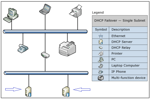
Hot standby mode of operation is best suited to deployments where a central office or data center server acts as a standby backup server to a server at a remote site, which is local to the DHCP clients (ex: hub and spoke deployment). In such deployments, it is undesirable to have a remote standby server service any clients unless the local DHCP server becomes unavailable. The figure below is an example of a hub and spoke deployment

Load Sharing Mode

In a load sharing mode deployment, which is the default mode of operation, the two servers simultaneously serve IP addresses and options to clients on a given subnet. The client requests are load balanced and shared between the two servers.

The load sharing mode of operation is best suited to deployments where both servers in a failover relationship are located at the same physical site. Both servers respond to DHCP client requests based on the load distribution ratio configured by the administrator

DHCP1

Instructions

  • First of all we need to install DHCP on the first of the two DHCP Servers
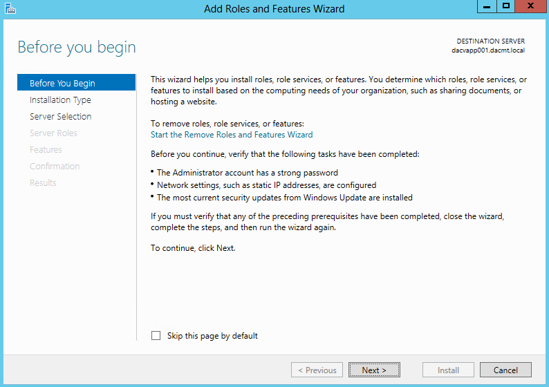
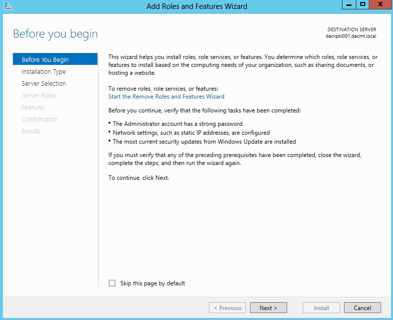
  • Open Server Manager and click Add Roles and Features

DHCP2

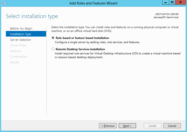
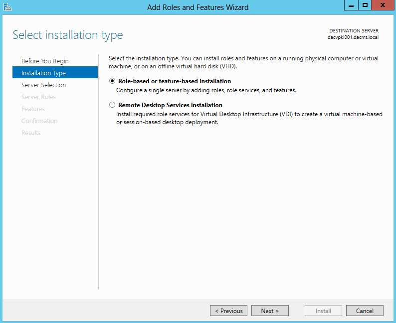
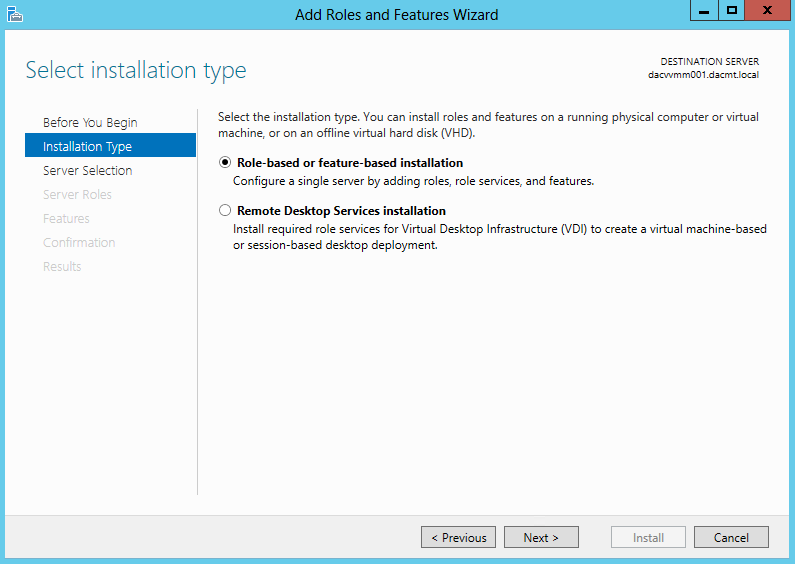
  • Select Installation Type > Choose Role based or Feature based installation

DHCP3

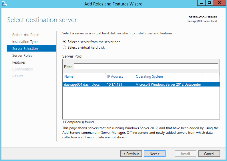
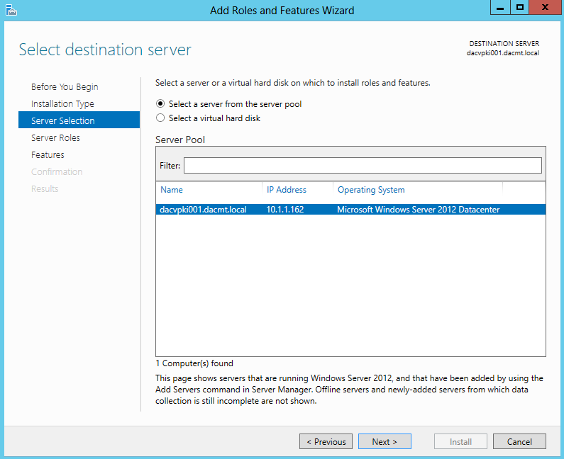
  • Select Destination Server

DHCP4

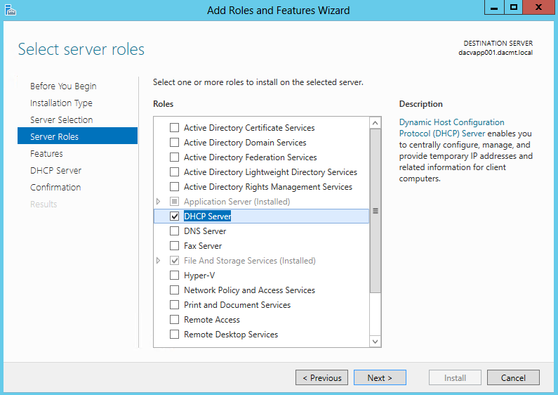
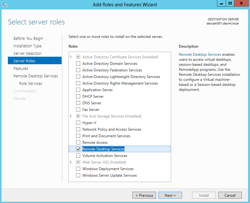
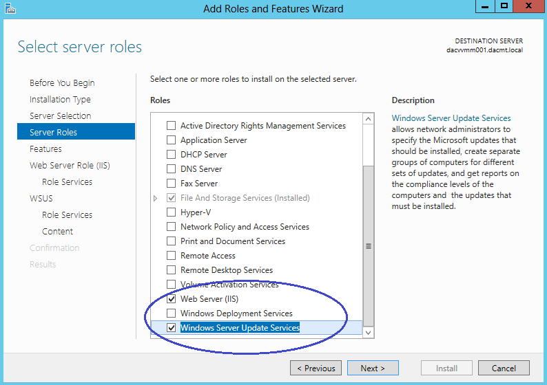
  • Select Server Role

DHCP5

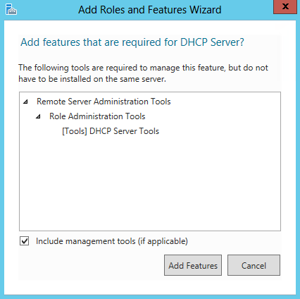
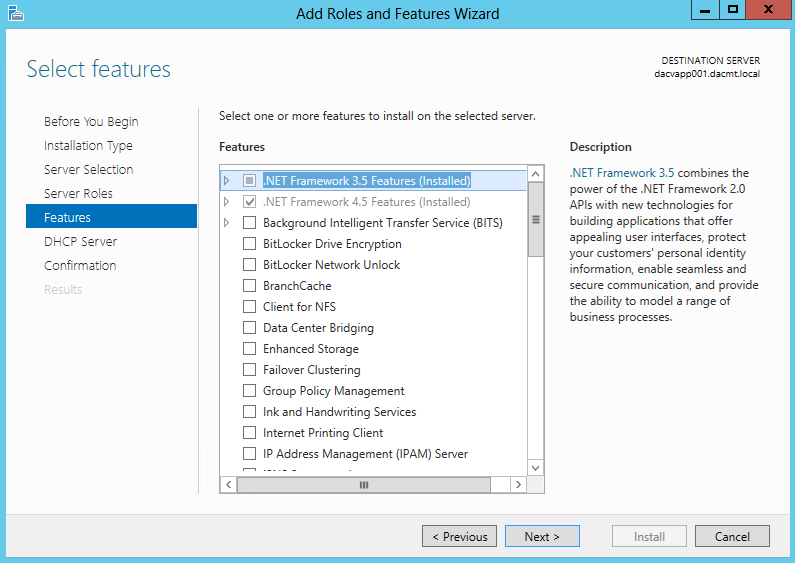
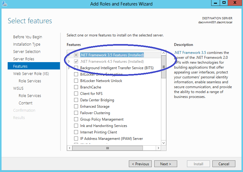
  • Select Features

DHCP6

  • Click Next on the Select Features Page

DHCP7

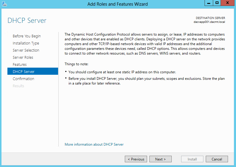
  • Click Next on the DHCP Server Page

DHCP8

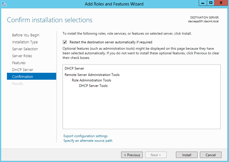
  • Click Next and Install

DHCP9

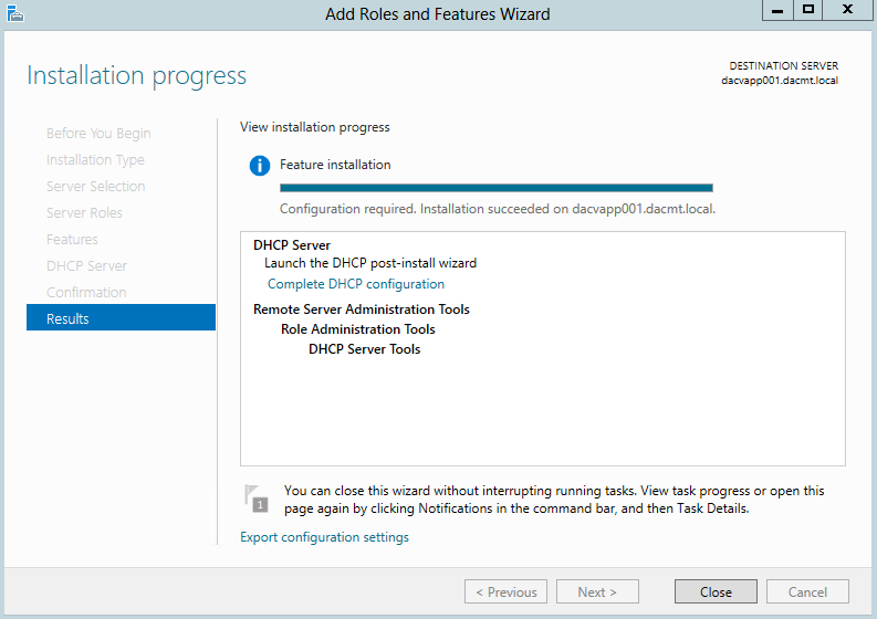
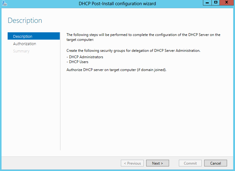
  • Once finished click Complete Configuration

DHCP10

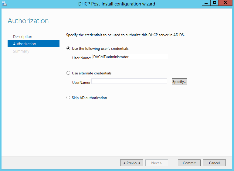
  • Before DHCP can be used as a Failover partner, it must be authorised in Active Directory
  • On the Post Installation Task screen click Next

DHCP11

  • On the Authorisation screen, add your DHCP User or use the Administrator

DHCP12

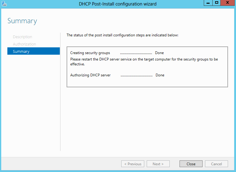
  • Click Commit and check the results

DHCP13

  •  Now you need to do exactly the same steps on your second DHCP Server
  • Go to the first DHCP Server and on the Server Manager menu bar, click Tools and then click DHCP. THE DHCP console opens.
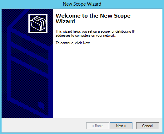
  • In the DHCP console tree, navigate to IPv4. Right-click IPv4 and then click New Scope. The New Scope Wizard opens.

DHCP14

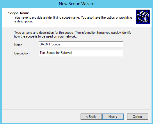
  • Click Next and then type a name for the new scope next to Name DACMT Scope

DHCP15

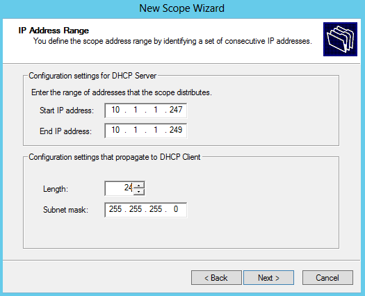
  • Click Next and then in IP Address Range, type 10.1.1.247 next to Start IP address, type 10.0.0.249 next to End IP address, and type 24 next to Length. The value of Subnet mask will change automatically to 255.255.255.0

DHCP16

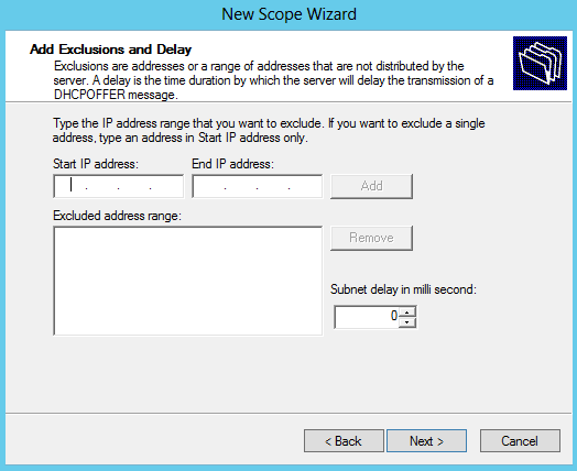
  • Click Next, and then don’t add anything in Add Exclusions and Delay.

DHCP17

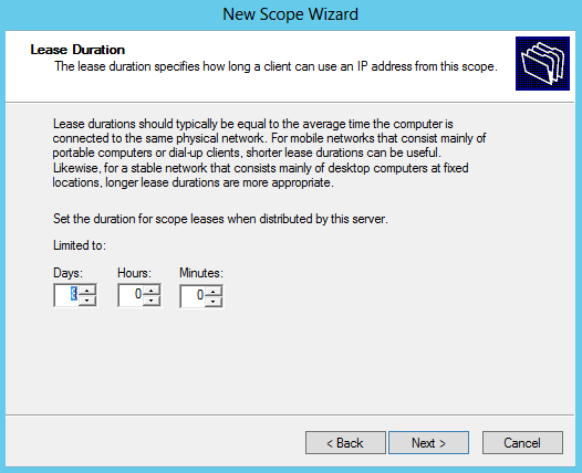
  • Click Next and then in Lease Duration under Limited to enter 0 Days, 0 Hours, and 2 Minutes. This very short lease duration will simplify the DHCP failover demonstration.

DHCP18

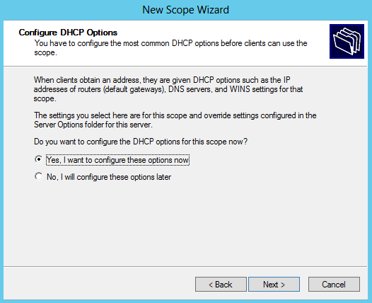
  • Click Next to DHCP Options

DHCP19

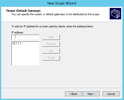
  • Add in your Router name and click Add

DHCP21

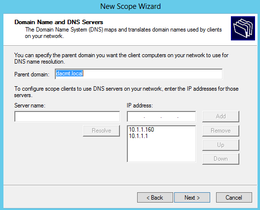
  • In Domain Name and DNS Servers, verify that the Parent domain is dacmt.local and 10.1.1.160 is listed as the only DNS server. (Check your own Domain and DNS Server here!)

DHCP22

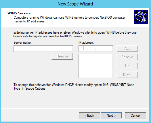
  • Ignore WINS Servers for now

DHCP23

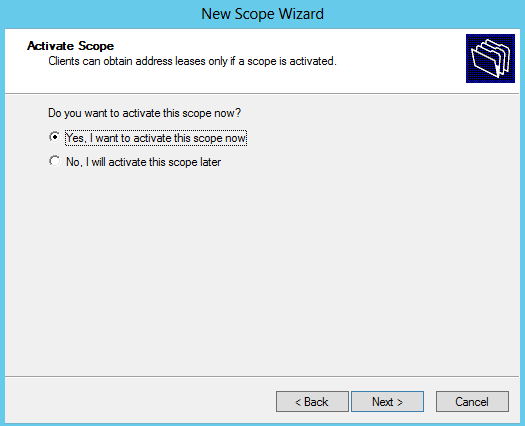
  • Select yes to activate the Scope now

DHCP24

  • In the DHCP console tree, right-click dhcp2.contoso.com, and then click Authorize.
  • Refresh the view in the DHCP console and verify that your DHCP Server is authorized and that the Scope is active.

DHCP25

  • Next we are ready to configure Failover
  • On your second DHCP Server where you have activated and specified the scope, right click the scope and select Configure Failover

DHCP26

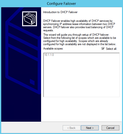
  • The Failover wizard will open. Click Next

DHCP27

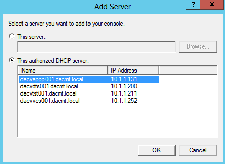
  • Specify the partner server you want to use. Click Add

DHCP28

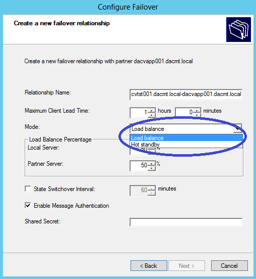
  • The next screen is the Create a Failover Relationship and this is where we have the different modes. (Load Balance or Hot Standby)
  • I am going to choose Load Balanced for now

DHCP30

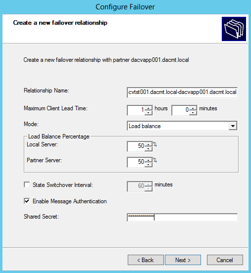
  • Type a shared secret for this failover relationship next to Shared Secret
  • Change the value next to Maximum Client Lead Time to 0 hours and 1 minute
  • The Maximum Client Lead Time (MCLT) is additional time provided to a DHCP client after expiration of a DHCP lease. The MCLT is transmitted from the primary to the secondary server in the CONNECT message, and is the maximum amount of time that one server can extend a lease for a client beyond the time known by the partner server.
  • In a production environment, you should use a longer MCLT, such as 1 hour.
  • So we should now look like the below screen

DHCP31

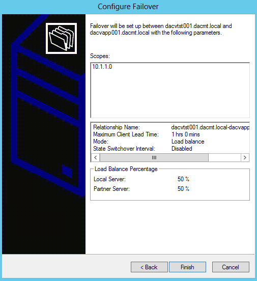
  • Click Next and review the settings

DHCP32

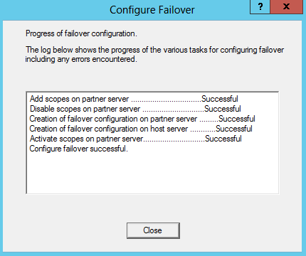
  • Check everything ran successfully in the box which pops up below

DHCP33

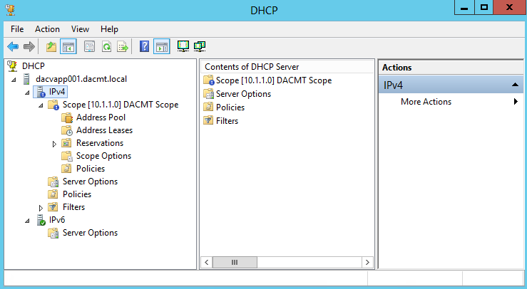
  • On your first DHCP Server, refresh the DHCP console and verify that the same DHCP scope configuration that is present on the second DHCP Server is now present on here

DHCP34

  • Voila, you have now set up one of the modes of DHCP Failover 🙂

Adding Excel 2010 Add-ins for all users on an RDS Farm

plus sign

The Requirements

To make 2 x Excel 2010 Add-ins load automatically whenever anyone logged into Excel 2010 on any RDS Server in the farm using their roaming profile

  • 4 x Windows 2008 R2 Remote Desktop Servers in an RDS Farm
  • 1 x Excel 2010 installed on each RDS Server
  • 2 x Excel 2010 Add-ins
  • Roaming Profiles
  • For testing purposes the D Drive was a trusted location in Excel (Via Group Policy)
  • For testing purposes, macros were enabled without prompting (Via Group Policy)

This was actually more complicated than it first looked. We found that on a per user basis when they manually add the add-ins through Excel then it retained the settings through the roaming profile no matter what server in the farm they were on which was great but we wanted to take the user aspect out of it

Adding Excel Add-ins (Unautomated)

  • Open Excel
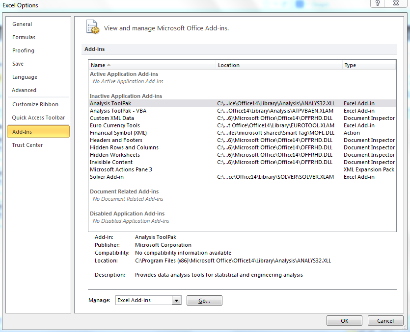
  • Click File > Options > Add-ins

Excel Add-ins2

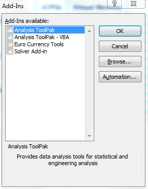
  • Click Go and you will see the default add-ins which come with Excel

Excel Add-ins3

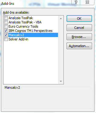
  • Browse to your Add-ins and select them
  • They should then show up

Excel Add-ins5

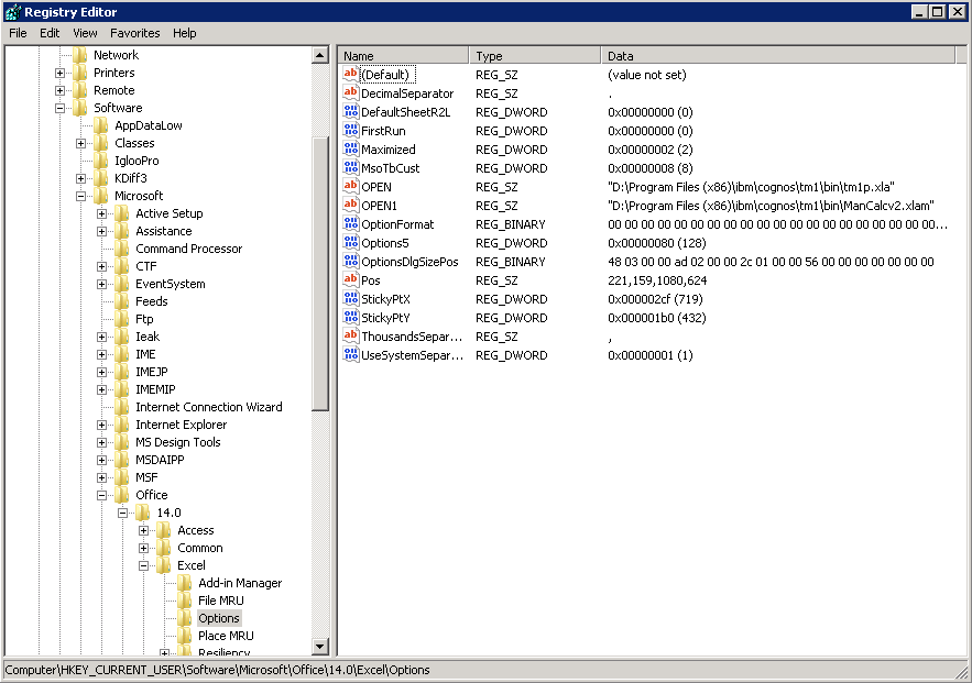
  • If you have a look in the registry then you will see the add-ins under the following paths. Note the first Add-in is called OPEN, the second is called OPEN1 and so on
  • HKEY_CURRENT_USER\Software\Microsoft\Office\14.0\Excel\Options\OPEN
  • HKEY_CURRENT_USER\Software\Microsoft\Office\14.0\Excel\Options\OPEN1

Excel Add-ins1

What we tested to start with

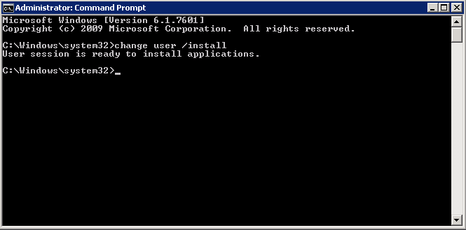
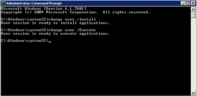
We thought it might be worth a try putting the RDS Server into Install mode and installing the Add-ins

Excel Add-ins6

  • Open Excel > File > Options > Add-ins > Go Install the Add-ins under an Admin account and then close Excel
  • Come out of Install Mode

Excel Add-ins7

  • But this didn’t work for any new users logging into the server either. The Add-ins did not appear but apparently this did work for someone who posted in a forum
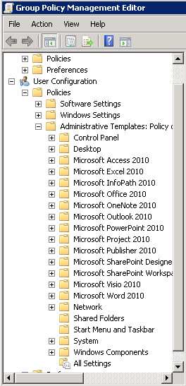
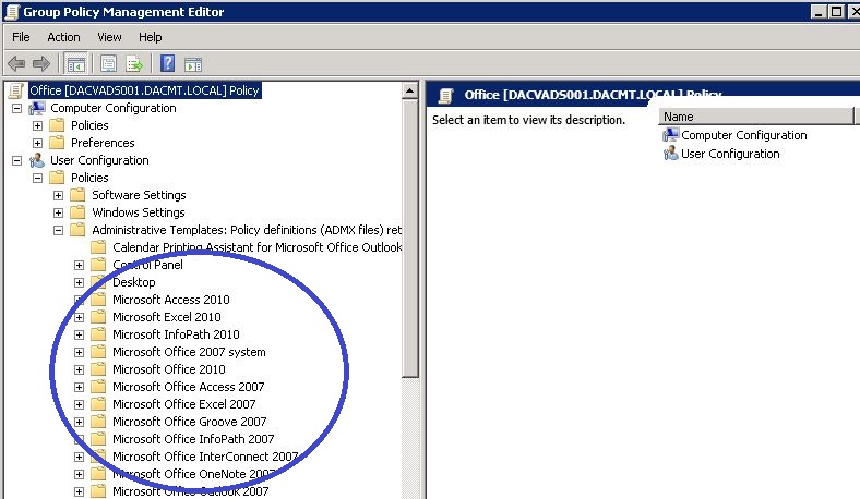
  • Next we had a look to see if we could use Group Policy. Note you have to download and install the relevant Microsoft Office Templates so you can see them in GPME. See below pic

Excel Add-ins8

  • But lo and behold there was not anything relating to Excel Add-ins or exactly what we needed. Apparently you are meant to be able to customise every aspect of Excel through GP but it sometime requires specialist knowledge and programming experience which we didn’t particularly want to get into.
  • Just as a note, we searched the web for a simple resolution to this and although you can find people with the same problem, we couldn’t find anyone who had this working
  • Next we will show you how we got this working via 3 methods. There may be other better solutions but these worked for us!

Working Solution 1 (Write a batch script containing reg syntax)

Bear in mind that this will be a brand new user logging into a server and opening Excel so we need to take into account that some of the necessary Office registry keys will not exist and we are using Office 2010.

The first thing we thought we could would be to write a short batch script which added the keys into the registry as per next 6 lines.

Note: If writing the below into Notepad then DO NOT USE WORD WRAP and note the “\” which enclose any path which has spaces

  • REG ADD HKEY_CURRENT_USER\Software\Microsoft\Office\ /f
  • REG ADD HKEY_CURRENT_USER\Software\Microsoft\Office\14.0\ /f
  • REG ADD HKEY_CURRENT_USER\Software\Microsoft\Office\14.0\Excel\ /f
  • REG ADD “HKEY_CURRENT_USER\Software\Microsoft\Office\14.0\Excel\ \Options\ /f
  • REG ADD HKEY_CURRENT_USER\Software\Microsoft\Office\14.0\Excel\Options\ /v OPEN /t REG_SZ /d “\”D:\Program Files (x86)\ibm\cognos\tm1\bin\tm1p.xla”\” /f
  • REG ADD HKEY_CURRENT_USER\Software\Microsoft\Office\14.0\Excel\Options\ /v OPEN1 /t REG_SZ /d “\”D:\Program Files (x86)\ibm\cognos\tm1\bin\ManCalcv2.xlam”\” /f
  • Here is what it looks like

regadd script

  • You can the save this as a .bat file and load it into a Group Policy to run at Startup or User Logon

The Second solution (PowerShell Script)

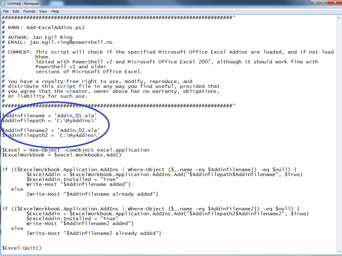
I found this PowerShell Script which adds Excel Addins. Thanks to Jan Egil Ring

http://poshcode.org/1811

  • Copy the script into a notepad file
  • Change the name of your Add-in (Circled below)
  • Change the Path to your Add-in (Circled below)
  • Save script with a .ps1 suffix

PowerShellexcel

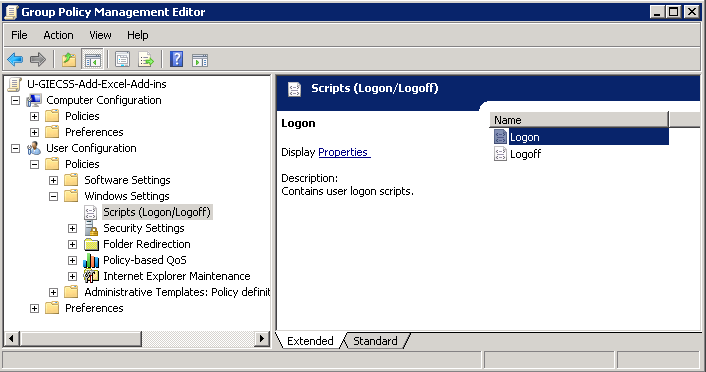
  • Next go to Group Policy
  • Create a new User Group Policy
  • Navigate to User Configuration > Windows Settings > Scripts (Logon/Logoff)

powershell02

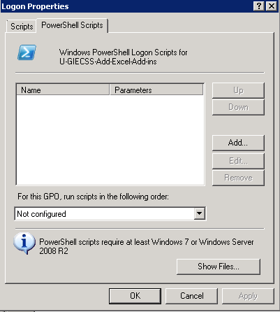
  • Double click on Logon
  • Click on PowerShell Scripts

powershell03

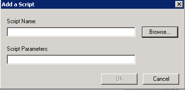
  • Click Add

powershell04

  • Click Browse
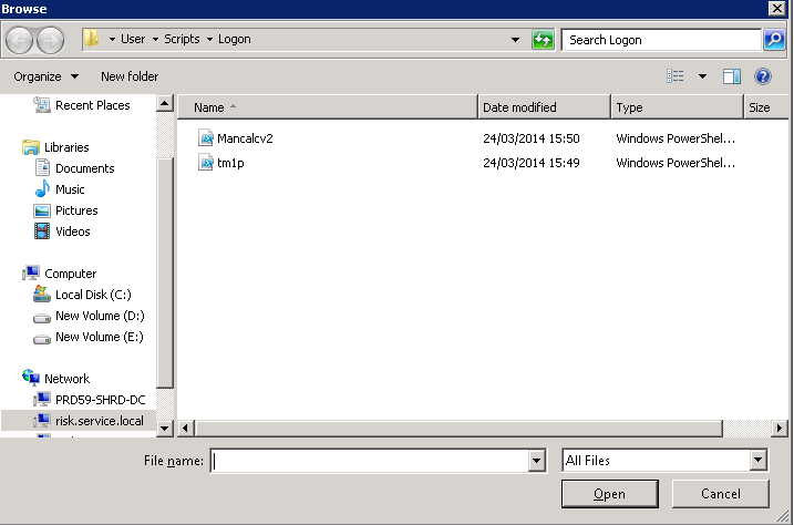
  • From here, I click Add, and click Browse. The Add a Script dialog appears. The Browse button opens a Windows Explorer window that is centered on the SysVol share for the domain. I then dragged and dropped my tm1p.ps1 script into the Logon script folder (SysVol Share)

powershell05

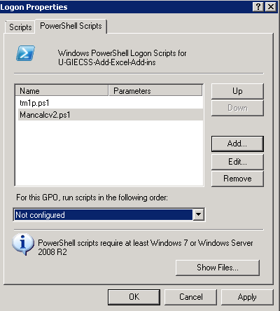
  • You should then see your script as per below screenprint

powershell06

  • Click Apply and OK
  • Go to the scope of the Policy and make sure the users or groups are selected for the policy
  • Open cmd.exe and type gpupdate /force
  • Try logging on as a brand new user to the server and see if the script runs and adds your Excel Add-in

The third Solution (Creating a Macro enabled Excel Template)

Thanks to Nicholas Cohen for providing this information

  • Open Excel 2010 on one of your RDS Servers
  • Press ALT F11 to open Visual Basic for Applications
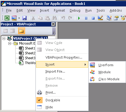
  • Right click on VBAProject (Book1) and select Insert > Module

Excel Add-ins9

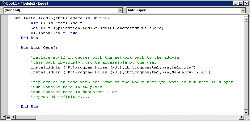
  • You will then need to copy and paste the following code into the module box

Sub InstallAddIn(strFileName As String)
Dim AI As Excel.AddIn
Set AI = Application.AddIns.Add(Filename:=strFileName)
AI.Installed = True
End Sub

Sub Auto_Open()

‘replace stuff in quotes with the network path to the add-in
‘this path obviously must be accessible by the user
InstallAddIn (“D:\Program Files (x86)\ibm\cognos\tm1\bin\tm1p.xla”)
InstallAddIn (“D:\Program Files (x86)\ibm\cognos\tm1\bin\ManCalcv2.xlam”)

‘replace below code with the name of the macro that you want to run when it’s open. You need to know names of what’s inside the Add-in to put here which is why this is commented out as an example but it will run anyway with the below path
‘code/routines in add-in tm1p.xla
‘code/routines in add-in Mancalcv2.xlam
‘repeat ad-infinitum….

End Sub

  • It should look like the below

Excel

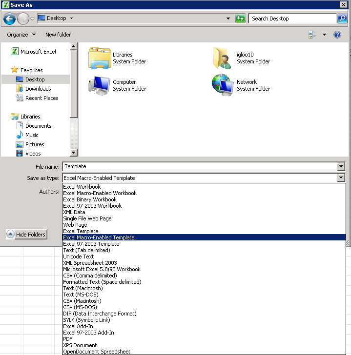
  • Now go back to Excel and do File > Save As >
  • Give it a name and save it as an Excel Macro-Enabled Template to the desktop or wherever convenient

Exceladdins21

  • Now the next task will be to put this Excel Template into the users roaming profile path under the XLSTART Folder which in most people’s case will be either of these 2 paths
  • \\server\Profiles\AppData\Roaming\Microsoft\Excel\XLSTART
  • \\server\Home\AppData\Roaming\Microsoft\Excel\XLSTART
  • Note: We redirect our users AppData folder to their home folder
  • This can then be scripted and put in a Group Policy

Exceladdins22

  • Next I’ll look at a script to do this but I haven’t got round to it yet as the PowerShell script seemed neater.

The Fourth Solution

This next solution was an added requirement to adding Excel Add-ins in a Terminal Server environment.

We had developers who logged into 2 different Terminal Server Farms and used different add-ins on each one. What we found is that the above scripts would sometimes overwrite existing add-ins when swapping from one farm to the next so we needed a script which checked if any of the Excel OPEN keys had values to start with, ignore them and add the Excel add-ins to the next available OPEN Key

Thanks very much to oBda of Experts Exchange for this script.

@echo off
setlocal enabledelayedexpansion
set AddinList[1]="D:\Program Files (x86)\ibm\cognos\tm1\bin\tm1p.xlam"
set AddinList[2]="D:\Program Files (x86)\ibm\cognos\tm1\bin\ManCalcv.xlam"
set Key=HKEY_CURRENT_USER\Software\Microsoft\Office\14.0\Excel\Options
set Quiet=0
set LastIndex=10
for /f "tokens=1* delims==" %%a in ('set AddinList[') do (
	if %Quiet%==0 echo Processing '%%b'
	set Value=
	set FoundAt=
	set Data=%%b
	set CompareData=!Data:"=!
	for /l %%i in (0, 1, %LastIndex%) do (
		if %%i==0 (set TestValue=OPEN) else (set TestValue=OPEN%%i)
		reg.exe query "%Key%" /v "!TestValue!" >NUL 2>&1
		if errorlevel 1 (
			if "!Value!"=="" (
				if %Quiet%==0 echo !TestValue! ... free.
				set Value=!TestValue!
			)
		) else (
			if %Quiet%==0 echo !TestValue! ... already used.
			for /f "tokens=2*" %%o in ('reg.exe query "%Key%" /v "!TestValue!"') do set CompareDataExisting=%%p
			set CompareDataExisting=!CompareDataExisting:"=!
			if /i "!CompareData!"=="!CompareDataExisting!" set FoundAt=!TestValue!
		)
	)
	if "!Value!"=="" (
		echo ERROR: Unable to find an empty index in the range of 0..%LastIndex%
		goto :eof
	)
	if "!FoundAt!"=="" (
		reg.exe add "%Key%" /v "!Value!" /t REG_SZ /d "!Data:"=\"!" /f >NUL
		if errorlevel 1 (
			echo ERROR: Could not create value '!Value!' with data '!Data!' at '%Key%'
		) else (
			if %Quiet%==0 echo Value successfully added.
		)
	) else (
		if %Quiet%==0 echo Found data in '!FoundAt!', nothing added.
	)
)

Installing the Microsoft Remote Desktop Gateway Role Service

gw

What is Microsoft Remote Desktop Gateway?

A Remote Desktop Gateway (RD Gateway) server is a type of gateway that enables authorized users to connect to remote computers on a corporate network from any computer with an Internet connection. RD Gateway uses the Remote Desktop Protocol (RDP) along with the HTTPS protocol to help create a more secure, encrypted connection.

In earlier versions of Remote Desktop Connection, people couldn’t connect to remote computers across firewalls and network address translators because port 3389—the port used for Remote Desktop connections—is typically blocked to enhance network security. However, an RD Gateway server uses port 443, which transmits data through a Secure Sockets Layer (SSL) tunnel.

Benefits of an RD Gateway server

  • Enables Remote Desktop connections to a corporate network from the Internet without having to set up virtual private network (VPN) connections.
  • Enables connections to remote computers across firewalls
  • Allows you to share a network connection with other programs running on your computer. This enables you to use your ISP connection instead of your corporate network to send and receive data over the remote connection.

How does RD Gateway work?

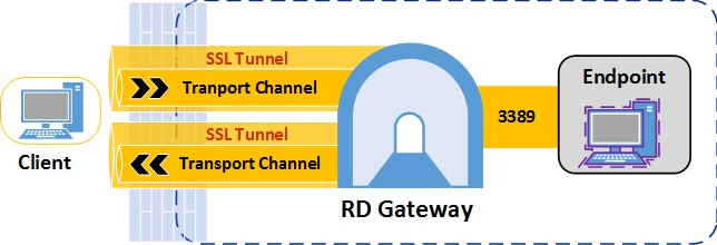
When a client makes a connection, RD Gateway first establishes SSL tunnels between itself and the external client. Next, RD Gateway checks the client’s user (and optionally the computer) credentials to make sure that the user / computer are authorized to connect to RD Gateway. Then RD Gateway makes sure the client is allowed to connect to the requested resource. If the request is authorized then RD Gateway sets up an RDP connection between itself and the internal resource. All communication between the external client and the internal endpoint goes through RD Gateway

Connections to RD Gateway use the RDGSP protocol. RDGSP creates two SSL tunnels (one for incoming data and one for outgoing data) from the external client to RD Gateway. Once the tunnels are established the client and RD Gateway establish a main channel over each tunnel. Data between client and the destination machine is sent over the channels and RD Gateway sits in the middle proxying the data back and forth

RD Gateway2

RDGSP uses a transport to create the channels.  In Windows Server 2008 R2, RDGSP used the RPC over HTTP transport. RPC over HTTP is still available for down-level RDP clients, but whenever available, RDP 8.0 clients will use the new and much more efficient HTTP transport. The difference is this: RPC over HTTP makes RPC calls for every data transfer to and from the client. This adds significant CPU overhead. The new HTTP transport does not have this overhead so it’s possible to accommodate up to twice as many RDP sessions on the same hardware.

Important Notes about Certificates

The certificate must meet these requirements:

  • The name in the Subject line of the server certificate (certificate name, or CN) must match the DNS name that the client uses to connect to the TS Gateway server, unless you are using wildcard certificates or the SAN attributes of certificates. If your organization issues certificates from an enterprise CA, a certificate template must be configured so that the appropriate name is supplied in the certificate request. If your organization issues certificates from a stand-alone CA, you do not need to do this.
  • The certificate is a computer certificate.
  • The intended purpose of the certificate is server authentication. The Extended Key Usage (EKU) is Server Authentication (1.3.6.1.5.5.7.3.1).
  • The certificate has a corresponding private key.
  • The certificate has not expired. We recommend that the certificate be valid one year from the date of installation.
  • A certificate object identifier (also known as OID) of 2.5.29.15 is not required. However, if the certificate that you plan to use contains an object identifier of 2.5.29.15, you can only use the certificate if at least one of the following key usage values is also set: CERT_KEY_ENCIPHERMENT_KEY_USAGE, CERT_KEY_AGREEMENT_KEY_USAGE, and CERT_DATA_ENCIPHERMENT_KEY_USAGE.
  • The certificate must be trusted on clients. That is, the public certificate of the CA that signed the TS Gateway server certificate must be located in the Trusted Root Certification Authorities store on the client computer

Checklist to install the Remote Desktop Gateway Role

  1. Install the Remote Desktop Gateway role service.
  2. Obtain a certificate for the RD Gateway server.
  3. Create a Remote Desktop connection authorization policy (RD CAP)
  4. Create a Remote Desktop resource authorization policy (RD RAP)
  5. Configure the Remote Desktop Services client for RD Gateway.

Install the Remote Desktop Gateway Role

  • Open Server Manager and select Add Roles and Features. You will get the Before you begin page. Click Next

rdgateway1

  • Select Installation Type. Choose Role based or Feature based Installation

rdgateway2

  • Select Destination Server

rdgateway3

  • Select Server Roles. Choose Remote Desktop Services

rdgateway4

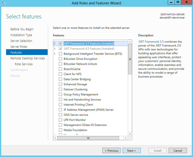
  • Click Next on Features

rdgateway5

  • Click Next on Remote Desktop Services Page
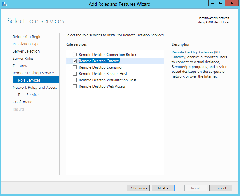
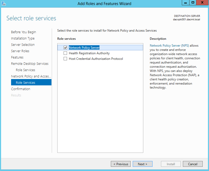
  • On the Select Role Services, choose Remote Desktop Gateway

rdgateway7

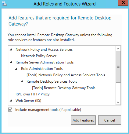
  • Click Add Features

rdgateway8

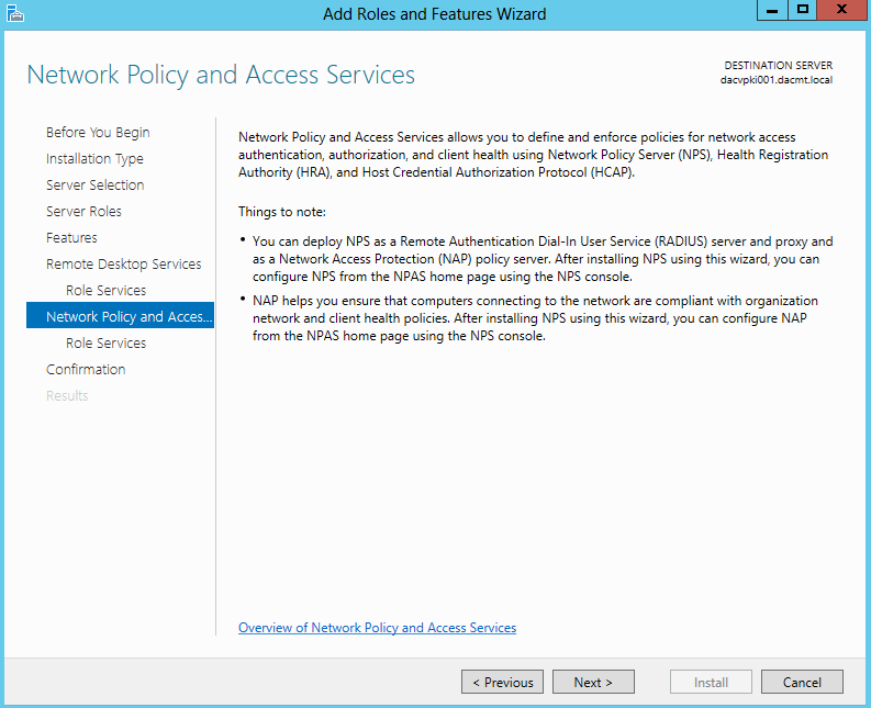
  • On the Network Policy and Access Screen, click Next

rdgateway9

  • Leave Network Policy Server checked

rdgateway10

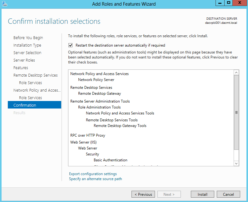
  • Confirm Installation Selections and click Install

rdgateway11

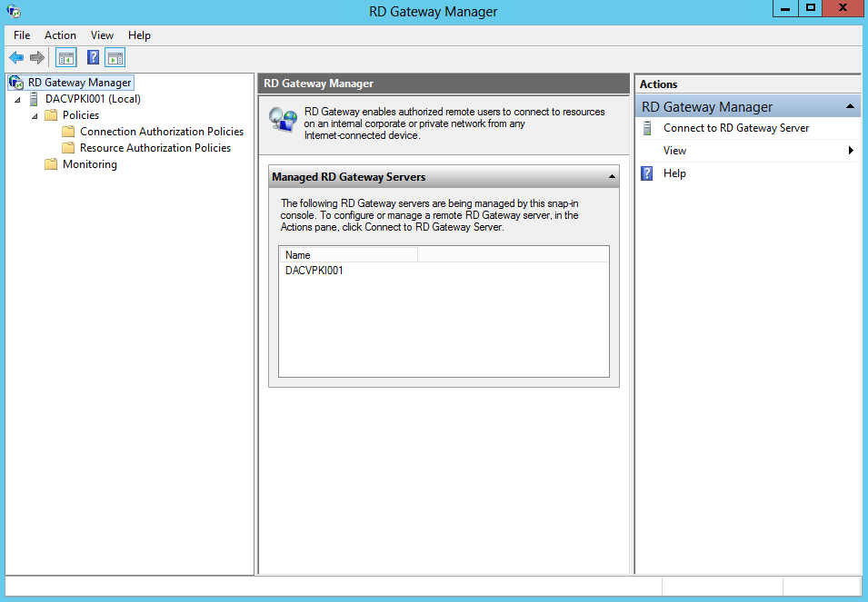
  • Next launch Remote Desktop Gateway Manager by going to Server Manager > Tools > Terminal Services > Remote Desktop Gateway Manager

rdgateway12

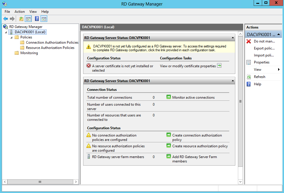
  • Select the Servername and you will see several messages to further configure this server

rdgateway13

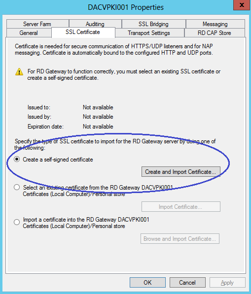
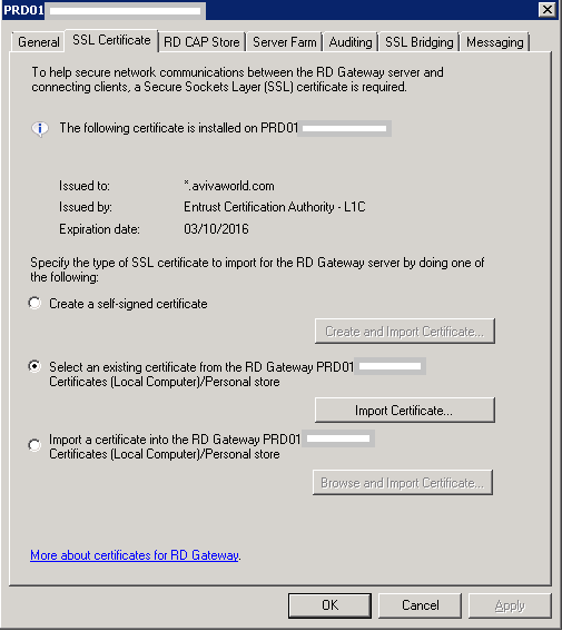
  • Select View or modify certificate properties
  • You do not need a certification authority (CA) infrastructure within your organization if you can use another method to obtain an externally trusted certificate that meets the requirements for TS Gateway. If your company does not maintain a stand-alone CA or an enterprise CA and you do not have a compatible certificate from a trusted public CA, you can create and import a self-signed certificate for your TS Gateway server for technical evaluation and testing purpose
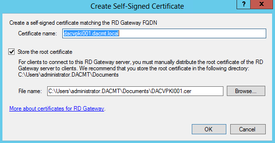
  • I am going to use a Self-Signed Certificate. Select Create and Import Certificate.

rdgateway14

  • The following screen will come up

rdgateway15

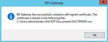
  • It will pop up with a confirmation box below

rdgateway16

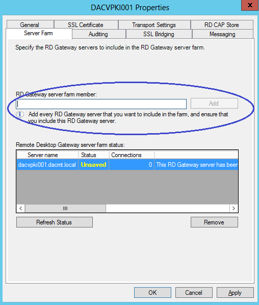
  • In the Server Farm tab, enter the name of the Remote Desktop Gateway Server and click Add
  • The add the second Remote Desktop Gateway Server etc if you have one

rdgateway17

  • Now have a look at the other settings
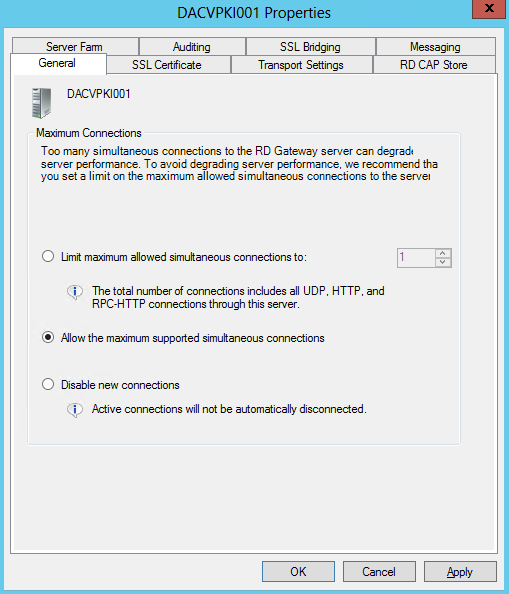
  • Look at General

rdgateway20

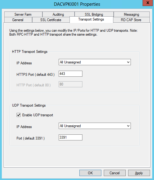
  • Look at Transport Setttings

rdgateway18

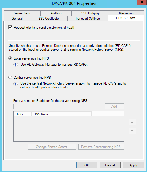
  • Next is RD CAP Store

rdgateway19

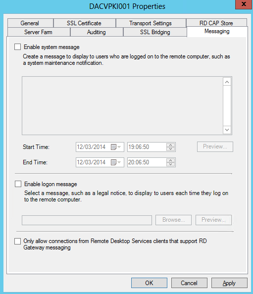
  • Look at Messaging

rdgateway21

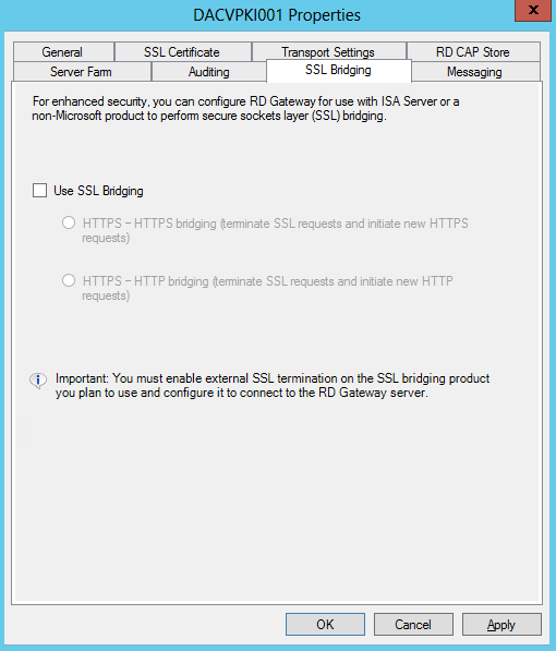
  • Look at SSL Bridging

rdgateway22

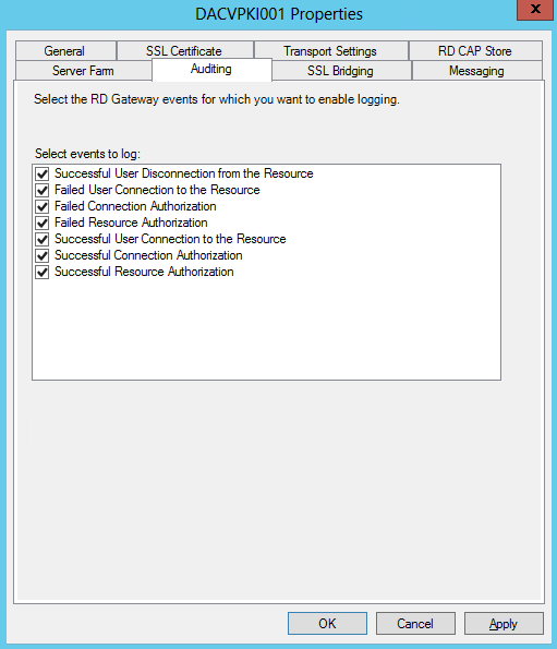
  •  Look at Auditing

rdgateway23

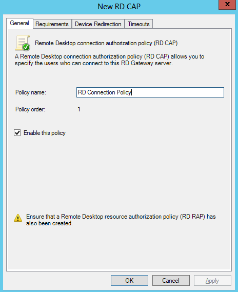
  • Now we need to define Connection Authorization Policy. Select Create connection authorization policy.

rdgateway24

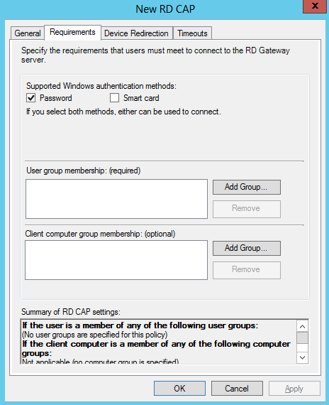
  • Click Requirements and add your User Groups or Computer Groups

rdgateway25

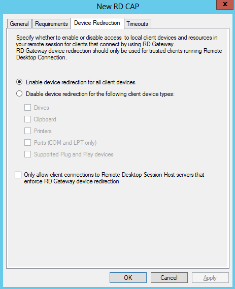
  • Click on Device Redirection

rdgateway26

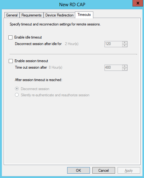
  • Click on Timeouts

rdgateway27

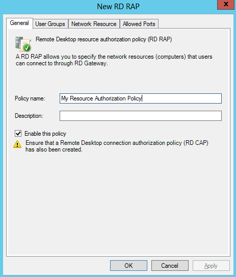
  • Next go back to the main console and create a resource authorization policy

rdgateway28

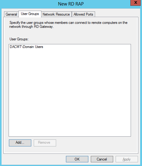
  • Click User Groups and add a group or groups

rdgateway29

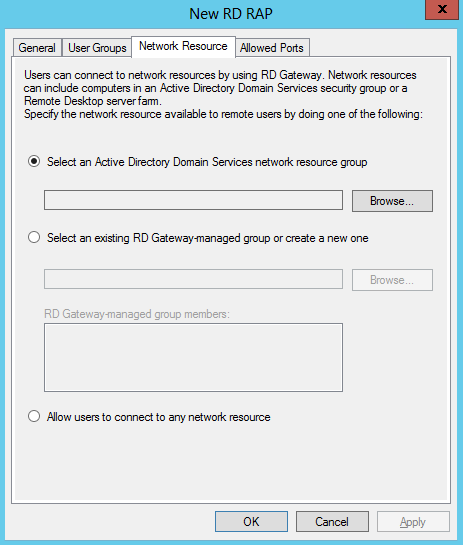
  • Click Network Resource

rdgateway30

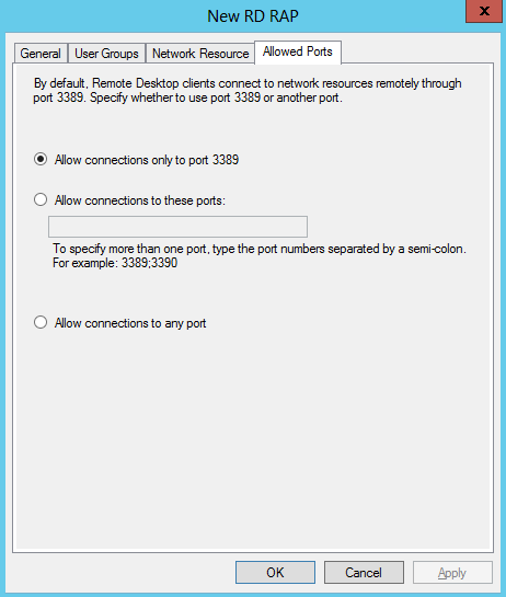
  • Click Allowed Ports

rdgateway31

  •  Complete
  • Now test your mstsc access!

Useful Step by Step Guide from Microsoft

http://technet.microsoft.com/en-us/library/cc771530%28v=ws.10%29.aspx

PDF Guide

TS Gateway Step by Step Guide

Useful Notes about Certificates

http://go.microsoft.com/fwlink/?LinkID=74577

Useful RD Gateway Firewall Blog

http://blogs.msdn.com/b/rds/archive/2009/07/31/rd-gateway-deployment-in-a-perimeter-network-firewall-rules.aspx

Resolving Issues

  • You must make sure you have the correct certificates. You must use a certificate with a SAN (Subject Alternative Name) and this must match the internal FQDN.

RDWEB4

  • You must make sure you have set up the correct RAPs and CAPs
  • You used password authentication but the TS Gateway server is expecting smart card authentication (or vice versa
  • Make sure you haven’t limited connections
  • Check DNS for individual servers and RDS Farms
  • Check Event Viewer on the Gateway Server > Event Viewer > Applications and Services Logs > Microsoft > Windows > TerminalServices-Gateway > Operational
  • You may have a Port assignment conflict. You can use netstat tool to determine if port 3389 (or the assigned RDP port) is being used by another application on the Remote Desktop server
  • Users must be a member of the Remote Desktop Group on the servers they want to connect to

If using RD Gateway with RD Web Access then it can be useful to check the following

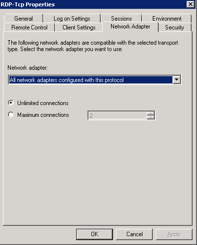
  • If you are using a Terminal Server Farm, you need to make sure the Start > All Programs > Administrative Tools >  Remote Desktop Services > Remote Desktop Session Host Configuration has the following set for Networking

RDWEB1

RDWEB2

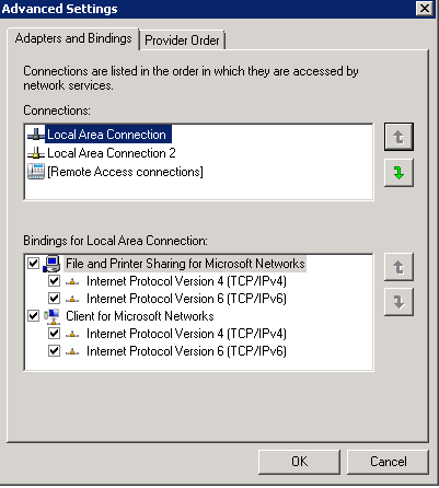
  • Sometimes you may need to check NIC Order in Network Connections

RDWEB3

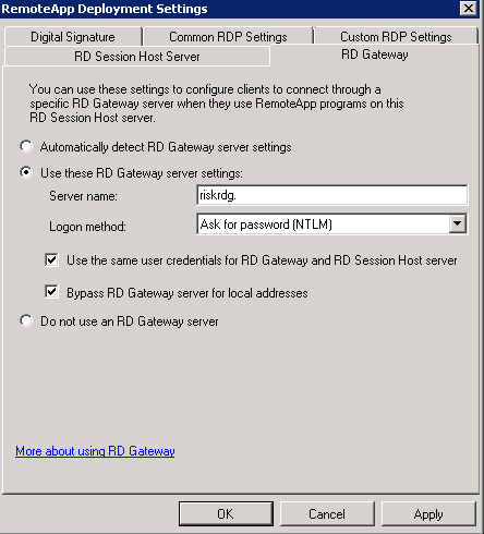
  • In RemoteApp Manager check you have a FQDN in your RemoteApp Deployment Settings and the port is correct
  • Check RD Gateway Settings are correct. Note I have blanked out the FQDN but this should be the case in these fields

RDWEB5

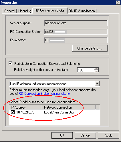
  • Make sure on each individual RDS Server in a farm that you have the Connection Broker Server and the RD Web Access Server.

Using Registry Keys using REG Commands

Cog

Using the REG Commands

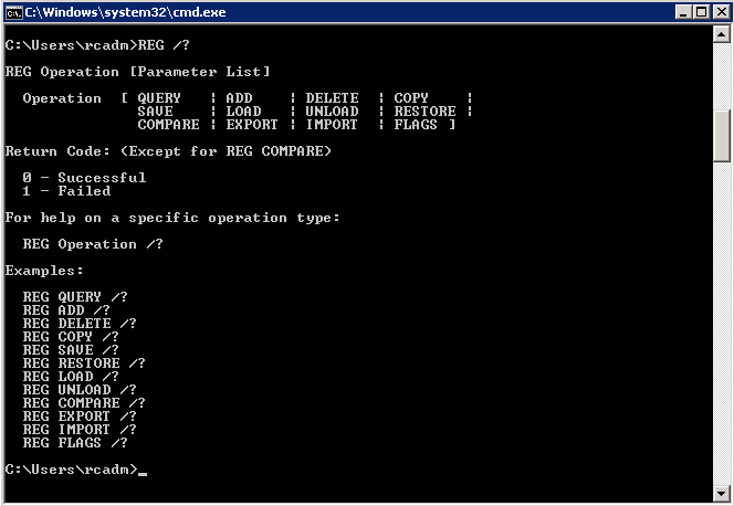
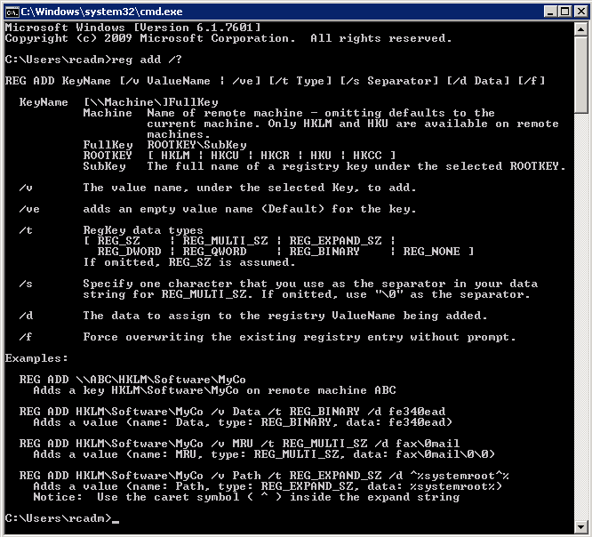
There are a lot of options and switches for the REG command. There are options to query, add, and delete keys, subkeys, and value names

reg add 2

The reason I have blogged about this is that we had to set some keys at my work and this works quite nicely if you write a bat script containing your relevant REG commands and add this to a GPO at User Logon

reg add

Writing a quick bat script

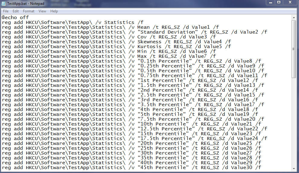
This is an example of something quick and easy to use

  • Open Notepad
  • Type Echo Off at the top to stop users seeing the script scrolling through
  • Look at the script below and see some of the switches and where to put quote marks etc

TestApp

  • The various switches you can use are listed in the screeprint above
  • You can then put this script for example on the C:\ of the server
  • Open Group Policy Management and create a new GPO
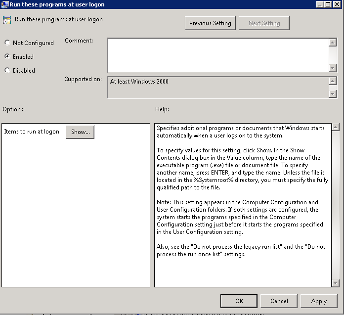
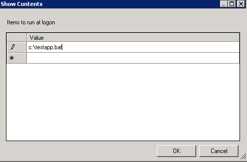
  • Navigate to User Configuration > Policies > Administrative Templates > System > Logon > Run these programs at user logon

app2

  • Click Show and type in the name of your script

app1

  • Link GPO to the Computer OU you need this applied to
  • Finish

Running a Hyper V VM within VMware vSphere 5.5

Windowsicon

The Issue

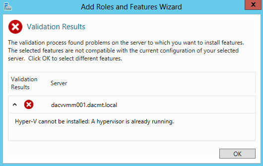
I wanted to set up 2 Microsoft Server 2012 Hyper V Hosts within my VMware 5.5 test environment but found that when it came to going through the Add Features > Hyper V component and selecting Hyper V that I received the message below

HypervErrror

The Fix

  • Shutdown the VM
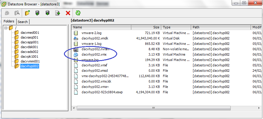
  • Go into the VMware Datastore and locate your Hyper V Folder
  • You need to locate the .vmx file and download it to your desktop

hyperverror2

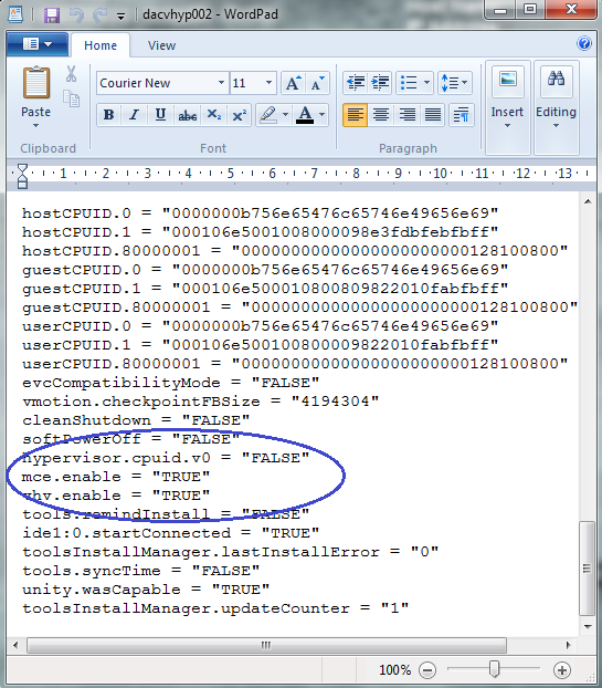
  • Open the vm.vmx file in Notepad and you will need to add the following 3 strings to the VM.vmx file
  • hypervisor.cpuid.v0 = “FALSE”
  • mce.enable = “TRUE”
  • vhv.enable = “TRUE”
  • See file screeprint below

hyperverror4

  • Power the machine on
  • Open Server Manager
  • Add Roles and Features
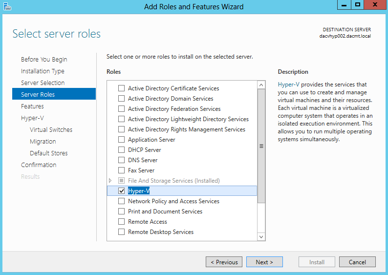
  • Select Hyper V

hyperverror5

  • You now should be able to install Hyper V


Group Policy and Microsoft Office Templates on Server 2008 R2

Policy

Managing Group Policy ADMX Files

Microsoft Windows Vista® and Windows Server 2008 introduce a new format for displaying registry-based policy settings. Registry-based policy settings (located under the Administrative Templates category in the Group Policy Object Editor) are defined using a standards-based, XML file format known as ADMX files. These new files replace ADM files, which used their own markup language. The Group Policy tools; Group Policy Object Editor and Group Policy Management Console remain largely unchanged. In the majority of situations, you won’t notice the presence of ADMX files during day-to-day Group Policy administration tasks.

ADMX files provide an XML-based structure for defining the display of the Administrative Template policy settings in the Group Policy tools. The Group Policy tools will recognize ADMX files only if you are using a Windows Vista–based or Windows Server 2008–based computer.

Unlike ADM files, ADMX files are not stored in individual GPOs. For domain-based enterprises, administrators can create a central store location of ADMX files that is accessible by anyone with permission to create or edit GPOs. Group Policy tools will continue to recognize custom ADM files you have in your existing environment, but will ignore any ADM file that has been superseded by ADMX files: System.adm, Inetres.adm, Conf.adm, Wmplayer.adm, and Wuau.adm. Therefore, if you have edited any of the these files to modify existing or create new policy settings, the modified or new settings will not be read or displayed by the Windows Vista–based Group Policy tools.

The Group Policy Object Editor automatically reads and displays Administrative Template policy settings from ADMX files that are stored either locally or in the optional ADMX central store. The Group Policy Object Editor will automatically read and display Administrative Template policy settings from custom ADM files stored in the GPO. You can still add or remove custom ADM files with the Add/Remove template menu option. All Group Policy settings currently in ADM files delivered by the Windows Server 2003, Windows XP, and Windows 2000 will also be available in Windows Vista and Windows Server 2008 ADMX files.

Note: I have tested the Co-Existence of the 2007 Microsoft Office Templates and the 2010 Microsoft Office Templates and they seem to work together nicely. See pic below. The same process applies to adding a second lot of templates

Office2007templates

Procedure

officegpo11

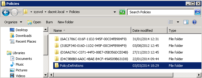
  • The central store is a folder structure created in the Sysvol directory on the domain controllers in each domain in your organization. You will need to create the central store only once on a single domain controller for each domain in your organization. The File Replication service then replicates the central store to all domain controllers in a domain. However, it is recommended that you create the central store on the primary domain controller. Group Policy Management Console and Group Policy Object Editor can use ADMX files more quickly because Group Policy tools connect to the primary domain controller by default.
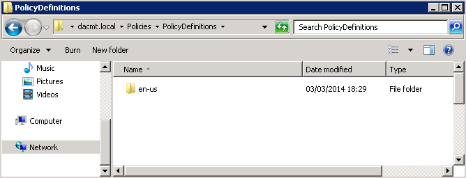
  • Create a subfolder of \\dacmt.local\sysvol\domain\Policies\PolicyDefinitions\en-us for each language your Group Policy administrators will use. Each subfolder is named after the appropriate ISO-style Language/Culture Name. E.g %domain%\sysvol\domain\policies\PolicyDefinitions\en-us

officegpo12

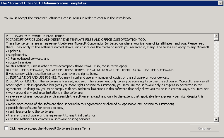
  • Run the Office 2010 Administrative Template exe as per below and save the 3 folders into a temp folder

officegpo1

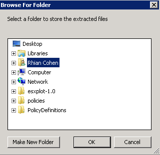
  • Save into a temp folder for now

officegpo2

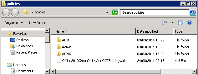
  • You should now see the following 3 folders

officegpo3

  • Go to your downloaded Office 2010 files and copy the admx files into the %domain%\sysvol\domain\policies\PolicyDefinitions folder
  • Go to your downloaded files and copy the adml files into the %domain%\sysvol\domain\policies\PolicyDefinitions\EN-US Folder
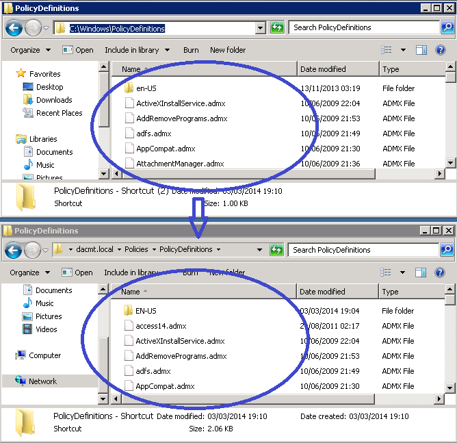
  • You now need to go to c:\Windows\Policy Definitions and copy what is in here into the \\dacmt.local\sysvol\domain\Policies\PolicyDefinitions\ folder and the \\dacmt.local\sysvol\domain\Policies\PolicyDefinitions\en-us folder as this will allow you to see the existing Administrative Templates along with the new Office ones

officegpo13

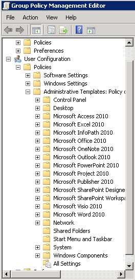
  • Open Group Policy Management console and you should now see the following

officegpo14

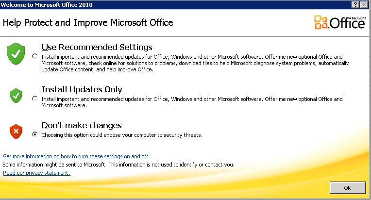
If you then navigate into each Office Setting. For example, go into Microsoft Office, you can suppress the initial box which pops up saying Welcome to Microsoft Office etc

officegpo10

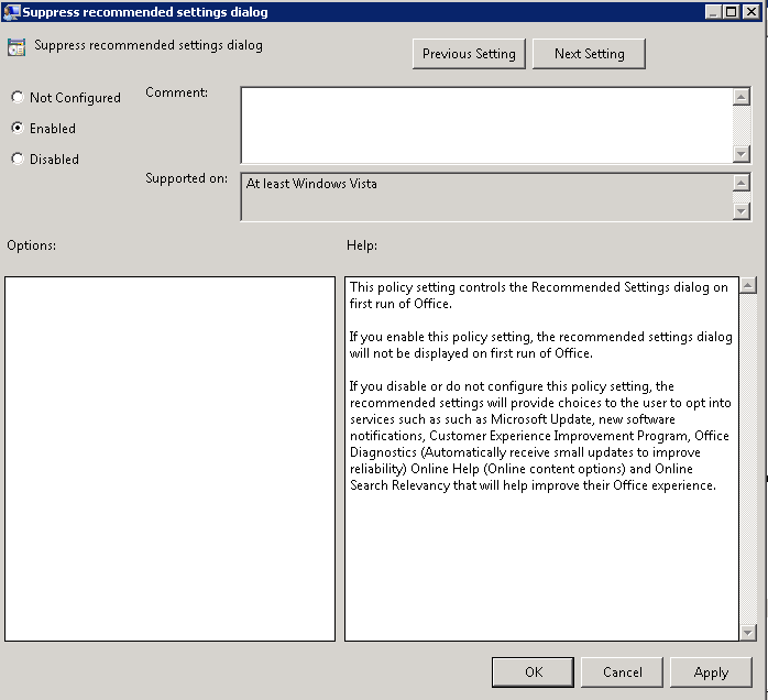
  • And this is the Group Policy below which will stop the above screen

officegpo9

  • Now you can go through any which you need to apply
  • Voila 🙂

Useful Links

http://technet.microsoft.com/en-us/library/cc748955%28v=ws.10%29.aspx

http://technet.microsoft.com/en-us/library/gg490629%28v=office.14%29.aspx

Understanding Active Directory Domain Services (AD DS) Functional Levels

level

What are Functional Levels?

Functional levels determine the available Active Directory Domain Services (AD DS) domain or forest capabilities. They also determine which Windows Server operating systems you can run on domain controllers in the domain or forest. However, functional levels do not affect which operating systems you can run on workstations and member servers that are joined to the domain or forest.

When you deploy AD DS, you need to set the domain and forest functional levels to the highest value that your environment can support. This way, you can use as many AD DS features as possible. For example, if you are sure that you will never add domain controllers that run Windows Server 2003 to the domain or forest, select the Windows Server 2008 functional level during the deployment process. However, if you might retain or add domain controllers that run Windows Server 2003, select the Windows Server 2003 functional level.

When you deploy a new forest, you are prompted to set the forest functional level and then set the domain functional level. You cannot set the domain functional level to a value that is lower than the forest functional level. For example, if you set the forest functional level to Windows Server 2008, you can set the domain functional level only to Windows Server 2008. In this case, the Windows 2000 native and Windows Server 2003 domain functional level values are not available. In addition, all domains that you subsequently add to that forest have the Windows Server 2008 domain functional level by default.

You can set the domain functional level to a value that is higher than the forest functional level. For example, if the forest functional level is Windows Server 2003, you can set the domain functional level to Windows Server 2003or higher.

Guidelines for raising domain and forest functional levels

  • You must be a member of the Domain Admins group to raise the domain functional level.
  • You must be a member of the Enterprise Admins group to raise the forest functional level.
  • You can raise the domain functional level on the primary domain controller (PDC) emulator operations master only. The AD DS administrative tools that you use to raise the domain functional level (the Active Directory Domains and Trusts snap-in and the Active Directory Users and Computers snap-in) automatically target the PDC emulator when you raise the domain functional level.
  • You can raise the forest functional level on the schema operations master only. Active Directory Domains and Trusts automatically targets the schema operations master when you raise the forest functional level.
  • You can raise the functional level of a domain only if all domain controllers in the domain run the version or versions of Windows Server that the new functional level supports.
  • You can raise the functional level of a forest only if all domain controllers in the forest run the version or versions of Windows Server that the new functional level supports.
  • You cannot set the domain functional level to a value that is lower than the forest functional level, but you can set it to a value that is equal to or higher than the forest functional level.
  • With versions of Windows Server that are earlier than Windows Server 2008 R2, you cannot roll back or lower a functional level under any circumstances. If you have to revert to a lower functional level with a version of Windows Server that is earlier than Windows Server 2008 R2, you must rebuild the domain or forest or restore it from a backup copy.
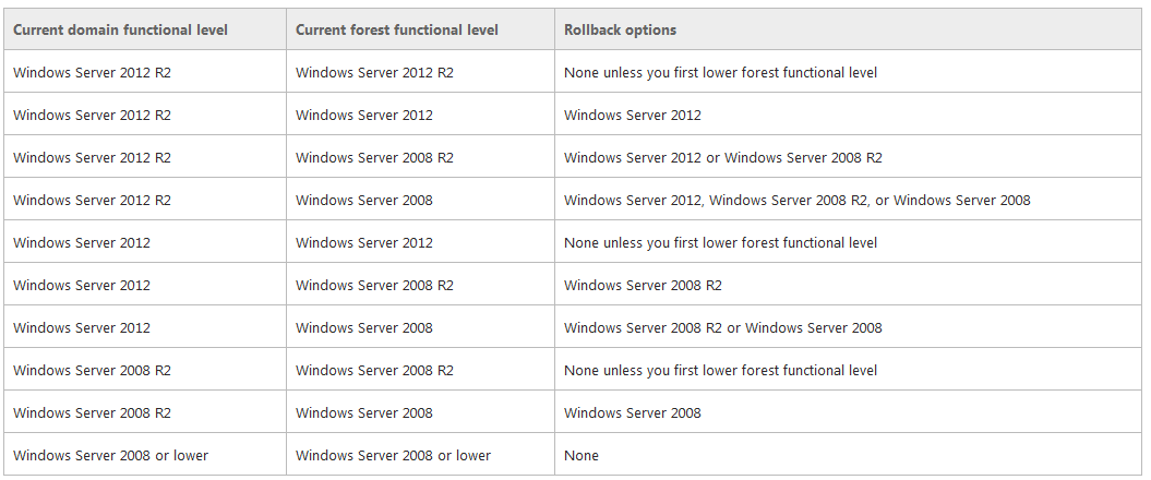
  • After you set the domain functional level, you cannot roll back or lower the domain functional level except in the cases listed in the following table. The domain functional level can be lowered only by using Windows PowerShell
Rollback

  • Make sure replication is working properly

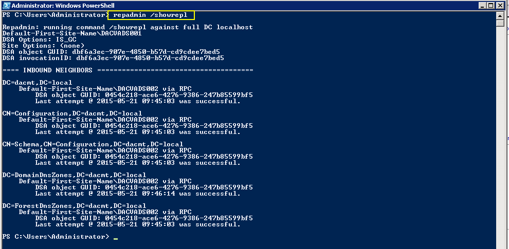
Checking Replication

  • repadmin /replsum

replication1

  • repadmin /showrepl

replication2

  • repadmin /bridgeheads

replication3

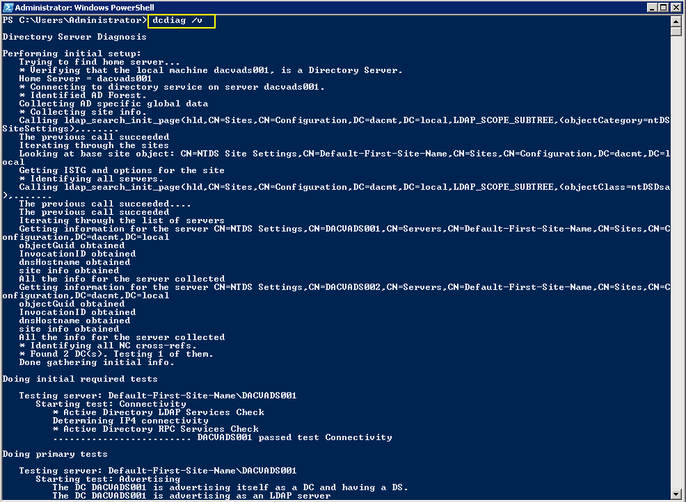
  • dcdiag /v (checking overall health of the domain)
replication4

Checking what Domain Controllers and FSMO roles you have

fsmo

Features available at Forest Function Levels

Windows 2003

  • Domain rename
  • Linked-value replication. Linked-value replication makes it possible for you to change group membership to store and replicate values for individual members instead of replicating the entire membership as a single unit. Storing and replicating the values of individual members uses less network bandwidth and fewer processor cycles during replication, and prevents you from losing updates when you add or remove multiple members concurrently at different domain controllers.
  • The ability to deploy a read-only domain controller (RODC)
  • Improved Knowledge Consistency Checker (KCC) algorithms and scalability. The intersite topology generator (ISTG) uses improved algorithms that scale to support forests with a greater number of sites than AD DS can support at the Windows 2000 forest functional level. The improved ISTG election algorithm is a less-intrusive mechanism for choosing the ISTG at the Windows 2000 forest functional level.
  • The ability to create instances of the dynamic auxiliary class named dynamicObject in a domain directory partition
  • The ability to convert an inetOrgPerson object instance into a User object instance, and to complete the conversion in the opposite direction
  • The ability to create instances of new group types to support role-based authorization.
    These types are called application basic groups and LDAP query groups.
  • Deactivation and redefinition of attributes and classes in the schema. The following attributes can be reused: ldapDisplayName, schemaIdGuid, OID, and mapiID.
  • Domain-based DFS namespaces running in Windows Server 2008 Mode, which includes support for access-based enumeration and increased scalability.

Windows 2008

All of the features that are available at the Windows Server 2003 forest functional level, but no additional features are available. All domains that are subsequently added to the forest, however, operate at the Windows Server 2008 domain functional level by default.

Windows 2008 R2

  • All of the features that are available at the Windows Server 2003 forest functional level, plus the following features:
  • Active Directory Recycle Bin, which provides the ability to restore deleted objects in their entirety while AD DS is running.
  • All domains that are subsequently added to the forest will operate at the Windows Server 2008 R2 domain functional level by default.
  • If you plan to include only domain controllers that run Windows Server 2008 R2 in the entire forest, you might choose this forest functional level for administrative convenience. If you do, you will never have to raise the domain functional level for each domain that you create in the forest.

Windows 2012

  • All of the features that are available at the Windows Server 2008 R2 forest functional level, but no additional features.
  • All domains that are subsequently added to the forest will operate at the Windows Server 2012 domain functional level by default

Windows 2012 R2

  • All of the features that are available at the Windows Server 2008 R2 forest functional level, but no additional features.
  • All domains that are subsequently added to the forest will operate at the Windows Server 2012 domain functional level by default

Features available at Domain Function Levels

Windows Server 2003

  • Universal groups for both distribution and security groups.
  • Group nesting
  • Group conversion, which allows conversion between security and distribution groups
  • Security identifier (SID) history
  • The domain management tool, Netdom.exe, which makes it possible for you to rename domain controllers
  • Logon time stamp updates
    The lastLogonTimestamp attribute is updated with the last logon time of the user or computer. This attribute is replicated within the domain.
  • The ability to set the userPassword attribute as the effective password on inetOrgPerson and user objects
  • The ability to redirect Users and Computers containers
    By default, two well-known containers are provided for housing computer and user accounts, namely, cn=Computers,<domain root> and cn=Users,<domain root>. This feature allows the definition of a new, well-known location for these accounts.
  • The ability for Authorization Manager to store its authorization policies in AD DS
  • Constrained delegation
    Constrained delegation makes it possible for applications to take advantage of the secure delegation of user credentials by means of Kerberos-based authentication.
    You can restrict delegation to specific destination services only.
  • Selective authentication
    Selective authentication makes it is possible for you to specify the users and groups from a trusted forest who are allowed to authenticate to resource servers in a trusting forest

Windows Server 2008

  • All of the default AD DS features, all of the features from the Windows Server 2003 domain functional level, and the following features are available:
  • Distributed File System (DFS) replication support for the Windows Server 2003 System Volume (SYSVOL)
    DFS replication support provides more robust and detailed replication of SYSVOL contents.
  • Beginning with Windows Server 2012 R2, File Replication Service (FRS) is deprecated. A new domain that is created on a domain controller that runs at least Windows Server 2012 R2 must be set to the Windows Server 2008 domain functional level or higher
  • Domain-based DFS namespaces running in Windows Server 2008 Mode, which includes support for access-based enumeration and increased scalability. Domain-based namespaces in Windows Server 2008 mode also require the forest to use the Windows Server 2003 forest functional level.
  • Advanced Encryption Standard (AES 128 and AES 256) support for the Kerberos protocol. In order for TGTs to be issued using AES, the domain functional level must be Windows Server 2008 or higher and the domain password needs to be changed.
  • Last Interactive Logon Information
  • Fine-grained password policies make it possible for you to specify password and account lockout policies for users and global security groups in a domain
  • Personal Virtual Desktops

Windows Server 2008 R2

  • All default Active Directory features, all features from the Windows Server 2008 domain functional level, plus the following features:
  • Authentication mechanism assurance, which packages information about the type of logon method (smart card or user name/password) that is used to authenticate domain users inside each user’s Kerberos token. When this feature is enabled in a network environment that has deployed a federated identity management infrastructure, such as Active Directory Federation Services (AD FS), the information in the token can then be extracted whenever a user attempts to access any claims-aware application that has been developed to determine authorization based on a user’s logon method.
  • Automatic SPN management for services running on a particular computer under the context of a Managed Service Account when the name or DNS host name of the machine account changes

Windows Server 2012

  • The KDC support for claims, compound authentication, and Kerberos armoring KDC administrative template policy has two settings (Always provide claims and Fail unarmored authentication requests) that require Windows Server 2012 domain functional level.

Windows Server 2012 R2

  • DC-side protections for Protected Users. Protected Users authenticating to a Windows Server 2012 R2 domain can no longer: Authenticate with NTLM authentication, Use DES or RC4 cipher suites in Kerberos pre-authentication, Be delegated with unconstrained or constrained delegation, Renew user tickets (TGTs) beyond the initial 4 hour lifetime
  • Authentication Policies: New forest-based Active Directory policies which can be applied to accounts in Windows Server 2012 R2 domains to control which hosts an account can sign-on from and apply access control conditions for authentication to services running as an account.
  • Authentication Policy Silos: New forest-based Active Directory object, which can create a relationship between user, managed service and computer, accounts to be used to classify accounts for authentication policies or for authentication isolation.

NTDSUTIL

This tool can remove old AD DC metadata which can stop the raising of Functional Levels

https://technet.microsoft.com/en-us/library/cc728068%28WS.10%29.aspx
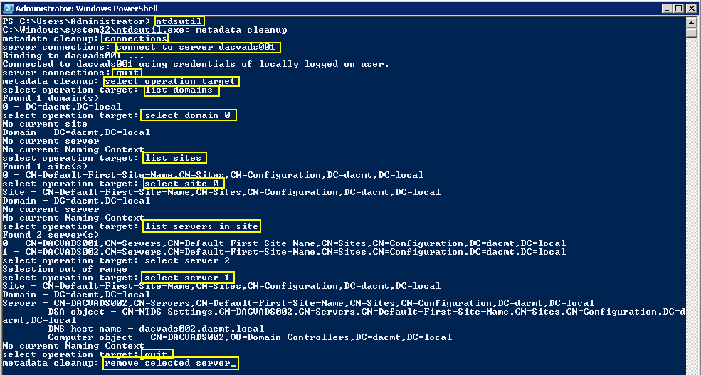
ntdsutil

The GUI Metadata Cleanup Utility

The GUI Metadata Cleanup Utility removes Active Directory domain controller metadata left behind after a domain controller is removed improperly or unsuccessfully

https://gallery.technet.microsoft.com/scriptcenter/d31f091f-2642-4ede-9f97-0e1cc4d577f3

Forest Recovery Information

https://technet.microsoft.com/en-us/library/8e3e4377-ef54-4a70-9215-a5d2ba4d0eb9%28v=ws.10%29#BKMK_ResetTrustPassword

http://blogs.technet.com/b/askds/archive/2011/06/14/what-is-the-impact-of-upgrading-the-domain-or-forest-functional-level.aspx

Useful Microsoft Link

https://technet.microsoft.com/library/understanding-active-directory-functional-levels%28WS.10%29.aspx

Questions?

  • Once you have upgraded the Domain functional level, how long should you wait before upgrading the forest functional level?

The change should take effect immediately as soon as the operation completes on the server. if you have multiple DC’s or domain, it may take longer. If you have plenty of time and want to play it safe, wait 24 hours but normally 15 minutes is fine. if you have multiple DC’s, you can log into each DC and verify the functional level.

  • By raising the root domain functional level, will this automatically raise any child domains or do we need to raise the level on the PDC of the root domain then raise the level on the PDC in the child domain? Or do we do the child first then the root domain?

Each individual domain PDCe is responsible for maintaining it’s domain functional level.  Because of this, where you raise the domain functional level first, does not matter (parent domain or child domain).  Each domain’s DC’s will operate at the domain functional level of it’s PDCe (so long as it is supported).  The Forest Functional Level affects all domains.  As such all domains must be operating at or above the proposed Forest Functional Level.

  • What is the best way to recover if things don’t go to plan? For e.g With a root domain with 2 DCs and a child domain with 5 DCs?

Before Windows Server 2008 R2, the only ways to recover are rebuild or restore from backup.

As the PDCe is responsible for the Domain Functional Level and the Schema Operations Master is responsible for the Forest Functional Level, first, you would have to restore the server that holds the Schema Operations Master in the Parent domain (if you will be reverting to a Domain Functional Level less than allowed by the Forest Functional Level). Then you would restore the server that holds the PDCe FSMO role for each child domain.

  • If we are running at Windows 2000 native domain level with all Windows 2008 R2 servers, can we raise the domain functional level straight to Windows Server 2008 R2?

If all of your DC’s are running Windows Server 2008 R2 then yes.
What is GNS3?

network2

What is GNS3?

GNS3 (Graphical Network Simulator) is an open source software that simulate complex networks while being as close as possible to the way real networks perform. All of this without having dedicated network hardware such as routers and switches.
This software provides an intuitive graphical user interface to design and configure virtual networks, it runs on traditional PC hardware and may be used on multiple operating systems, including Windows, Linux, and MacOS X.

In order to provide complete and accurate simulations, GNS3 actually uses the following emulators to run the very same operating systems as in real networks:

  • Dynamips, the well known Cisco IOS emulator.
  • VirtualBox, runs desktop and server operating systems as well as Juniper JunOS.
  • Qemu, a generic open source machine emulator, it runs Cisco ASA, PIX and IPS

Who can use it?

GNS3 is an excellent alternative or complementary tool to real labs for network engineers, administrators and people studying for certifications such as Cisco CCNA, CCNP and CCIE as well as Juniper JNCIA, JNCIS and JNCIE. Open source networking is supported too.

It can also be used to experiment with features or to check configurations that need to be deployed later on real devices.
Their programs includes exciting features, for instance connection of your virtual network to real ones or packet captures using Wireshark.
Where do I start?

In most situations, to use GNS3 you first need to provide your own copy of a network operating system, like Cisco IOS, PIX, ASA, IPS or Juniper JunOS. GNS3 also suggest ready to use non-copyrighted appliances.
Once you have your operating system, start reading the GNS3 documentation and learn how to use GNS3. Watching video tutorials is also a good way to better understand the program.

Installing GNS3

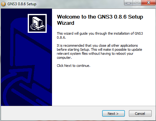
  • Double click on the installer

gns31

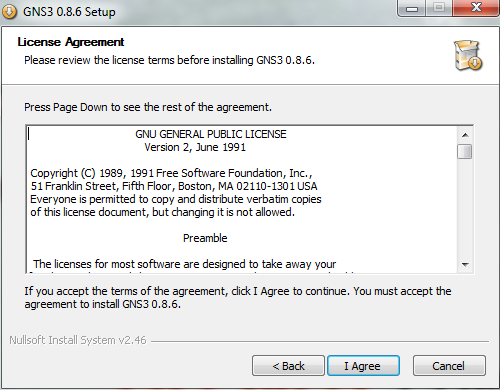
  • Accept the license agreement

gns32

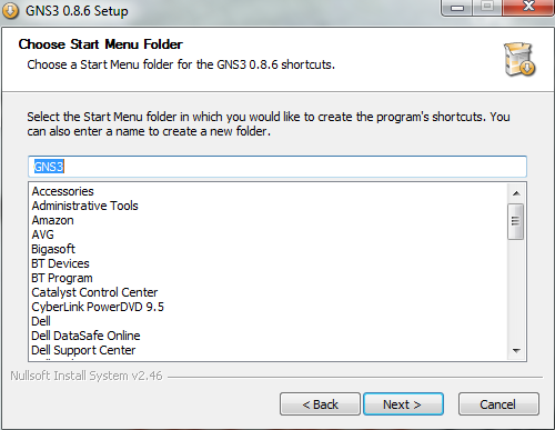
  • Choose Start Menu Folder

gns33

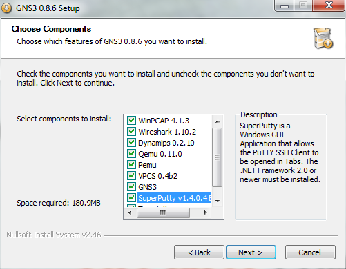
  • Choose Components

gns34

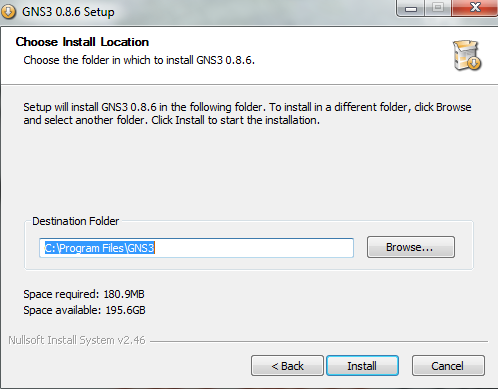
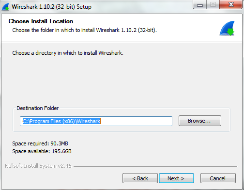
  • Choose Install Location

gns35

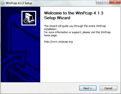
  • The installer will launch into the WinPcap Setup Wizard

gns36

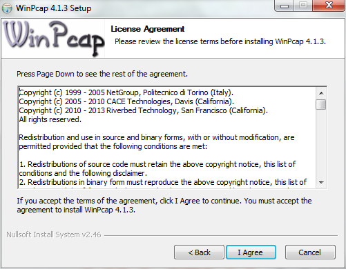
  • Accept the License Agreement

gns37

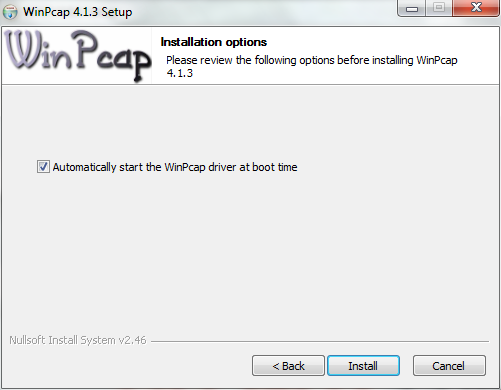
  • Click Install

gns38

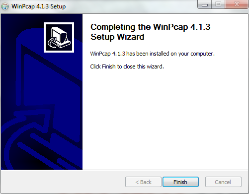
  • Click Finish

gns39

  • Next the Wireshark installer will begin

gns310

  • Accept the License Agreement

gns311

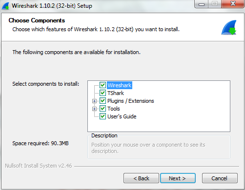
  • Choose Components

gns312

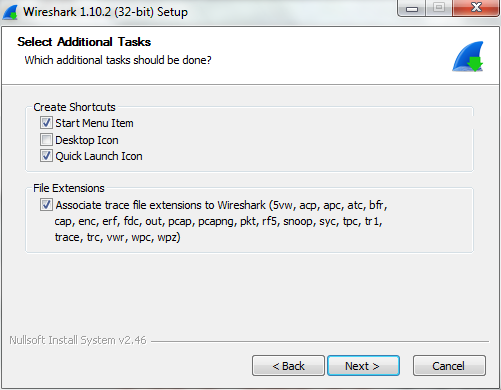
  • Select Additional Tasks

gns313

  • Choose Install Location

gns14

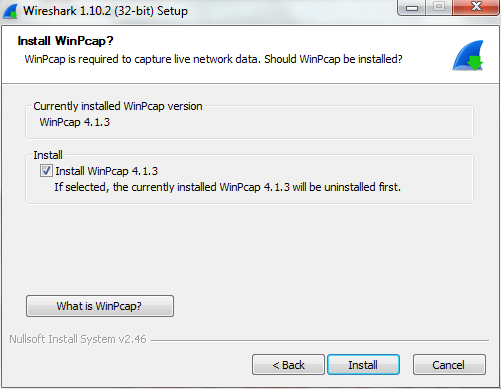
  • Next Untick Install WinPcap as it is already installed

gns315

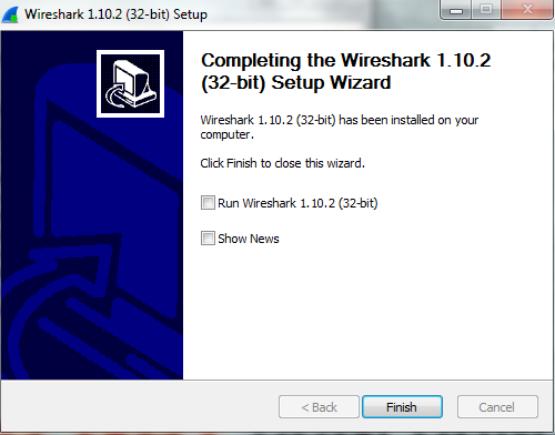
  • Wireshark will now complete

gns316

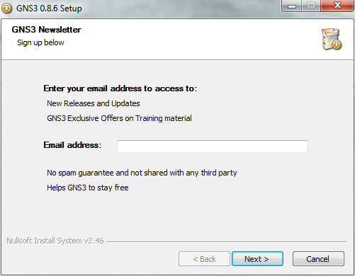
  • GNS3 Setup will now continue

gns317

  • Enter your email address

gns318

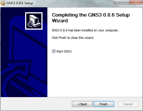
  • Finish and Start GNS3

gns319

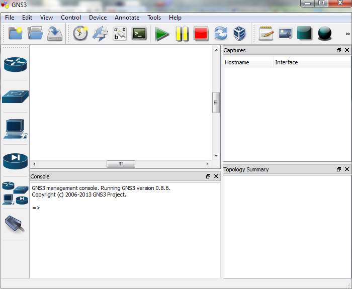
  • This is the first screen you will see

gns321

  • As mentioned earlier, you must provide your own Cisco IOS to use with GNS3 due to licensing issues
  • Once you have obtained your own copy of a Cisco IOS for one of the supported platforms, you are ready to continue. Supported platforms are Cisco 7200, 3600 series (3620, 3640 and 3660), 3700 series (3725, 3745) and 2600 series (2610 to 2650XM, 2691)
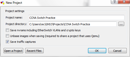
  • When you open GNS3, You may get a Project Prompt as per below screenprint

gns325

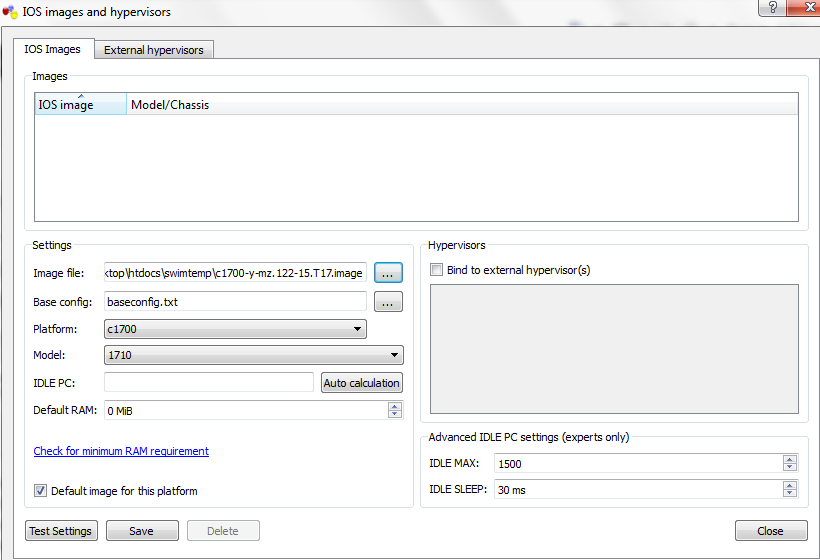
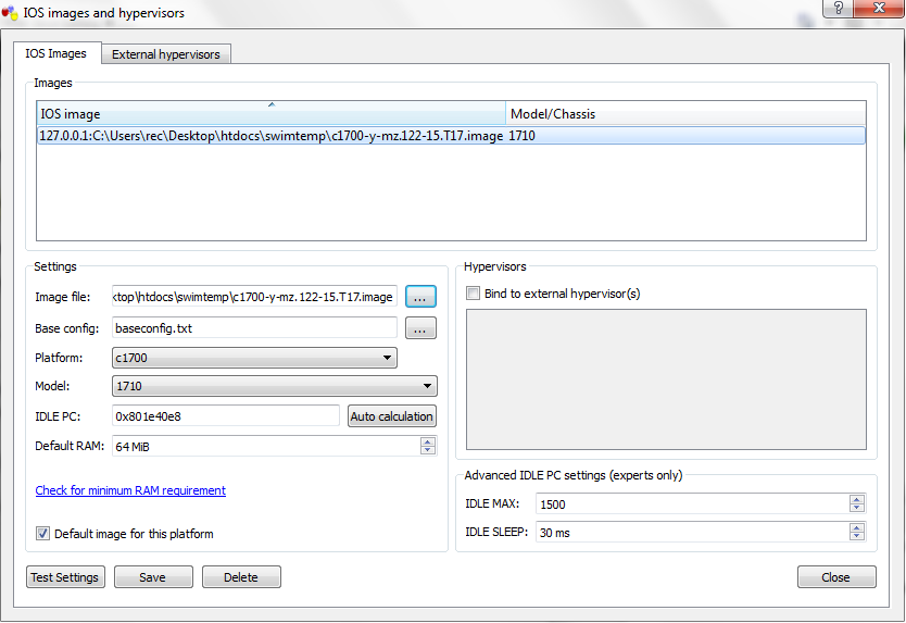
  • On the Edit menu, choose IOS image and hypervisors. Then under the IOS Images tab, click … and then find your Cisco IOS file and click Open. The file will appear as your Image file. Next, click the drop-down arrow next to Platform and choose the platform that corresponds to your IOS file
gns326

  • You may get a message about decompressing the file

gns327

  • Now click the drop-down arrow next to Model and choose the model corresponding to your IOS file. I am using C1700 and a model of C1710For now, we’ll accept the default values that remain. However, there is a very important value called the IDLE PC value that we will want to include. We’ll get to that later. Click the Save button and then the Close button. This will return you to the default GNS3 window
  • If you get a message about Dynamips when you click Save, then go to Tools, Dynamips Server and click on it.. it will start and then prompt you about a Firewall issue which you can select to allow for your network.

gns328

  • Just a note on the IDLE PC value you can see in the screen above. We will need to learn how to find an IDLE PC value for the IOS we are using. This is a very important step. When an IOS is running, it will consume up to 100% of your CPU time. This will cause your computer to become very sluggish and will prevent building more complex topologies. However, if we use an IDLE PC value, we can reduce CPU usage dramatically. It puts the IOS into a sleep state when it is not in active use and wakes it up only when it is necessary.
  • So click on your router in the pane circled below and click the Green Run arrow

gns331

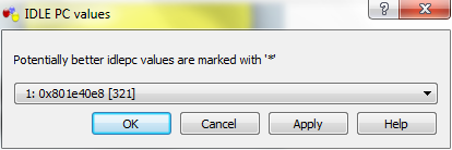
  • Now it’s time to choose a idlepc value. Be sure you can see the prompt of your router in Putty window. Right-click R1 and choose IDLE PC. GNS3 will spend a moment calculating an Idle PC value

gns332

  • Next it will show you the screen below. If you click the drop-down arrow, you see a list of possible IDLE PC values. Potentially better IDLE PC values are marked with an asterisk. Choose one of the values with an asterisk (in our example, we will choose number 1) and click OK.

gns333

  • If you choose IOS images and hypervisors on the Edit menu, and double-click on the image under the IOS Images tab, you’ll see the new IDLE PC value displayed under Settings

gns334

  • Next Right click on your router (On the icon in the middle panel) and select Console

gns335

  • Now you are ready to have a play! 🙂
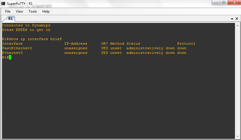
  • If you issue the show ip interface brief command as shown, you’ll see the designations.

gns336

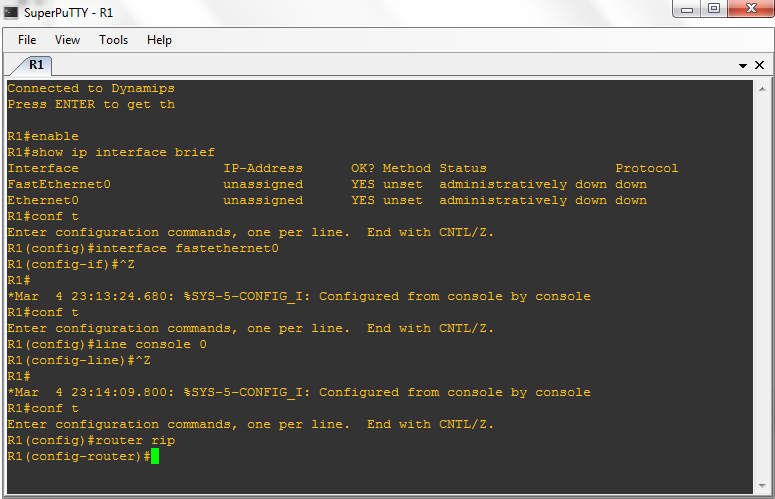
  • Carry on seeing what you can do especially if you are doing your CCNA and have exercises you can do. Some examples below
  • The first mode you will be presented with is known as the User Mode or User Exec Mode. This has a limited set of commands
  • enable will take you into the next mode known as Privileged Mode or Privileged Exec Mode useful for looking at the entire configuration, statistics and modules you have attached to the router
  • show ip interface brief will show you the interfaces you have
  • conf t will take you into the Global Configuration Mode
  • interface fastethernet0 will take you into the interface configuration mode
  • line console 0 will allow you to make changes to the console, Telnet or auxiliary ports
  • Ctl+Z will take you back to the previous mode

GNS330

Using WSUS with Microsoft Virtual Machine Manager 2012

shield

What is WSUS?

The Windows Server Update Service (WSUS) enables information technology administrators to deploy the latest Microsoft product updates. By using WSUS, administrators can fully manage the distribution of updates that are released through Microsoft Update to computers in their network. This blog shows an overview of this server role and more information about how to deploy and maintain WSUS via Microsoft Virtual Machine Manager 2012. The WSUS server provides the features that administrators need to manage and distribute updates through a management console. In addition, a WSUS server can be the update source for other WSUS servers within the organization. The WSUS server that acts as an update source is called an upstream server. In a WSUS implementation, at least one WSUS server in the network must connect to Microsoft Update to get available update information. The administrator can determine, based on network security and configuration, how many other servers connect directly to Microsoft Update

Installing WSUS

  • You can choose to install WSUS on a Remote Server
  • You can choose to install WSUS on a VMM Server which is what we are going to do

Installation Considerations:

During the installation process, WSUS will install the following by default:

  • .NET API and Windows PowerShell cmdlets
  • Windows Internal Database (WID), which is used by WSUS unless you configure WSUS to connect to another DB Instance on a separate server to the VMM Server
  • Services used by WSUS, which are:
    • Update Service
    • Reporting Web Service
    • Client Web Service
    • Simple Web Authentication Web Service
    • Server Synchronization Service
    • DSS Authentication Web Service

By default, the WSUS server uses port 8530 for HTTP protocol and port 8531 for HTTPS protocol to obtain updates from Microsoft. If there is a corporate firewall between your network and the Internet, you will have to open these ports on the server that communicates directly to Microsoft Update. If you are planning to use custom ports for this communication, you open those ports instead

Pre Requisites

  • The database server cannot be configured as a domain controller.
  • The WSUS server cannot run Remote Desktop Services.
  • The database server must be in the same Active Directory domain as the WSUS server, or it must have a trust relationship with the Active Directory domain of the WSUS server.
  • The WSUS server and the database server must be in the same time zone or be synchronized to the same Coordinated Universal Time (Greenwich Mean Time) source
  • Check server hardware requirements to enable WSUS role are bound to hardware requirements.
  • Check if you install roles or software updates that require you to restart the server when installation is complete, restart the server before you enable the WSUS server role.
  • Microsoft .NET Framework 3.5/4.0 must be installed on the server where the WSUS server role will be installed. Can be selected when you go through adding roles
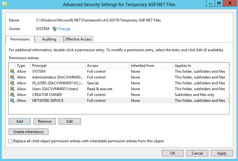
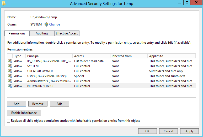
  • The NT Authority\Network Service account must have Full Control permissions for the following folders so that the WSUS Administration snap-in displays correctly: This path may not exist until you have installed the IIS role
  • %windir%\Microsoft.NET\Framework\v4.0.30319\Temporary ASP.NET Files

wsus

  • %windir%\Temp

wsus00

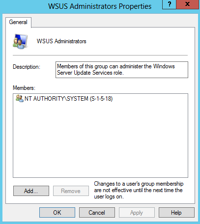
  • Assign the Local System account to the WSUS Administrators Group

wsus0 Installation

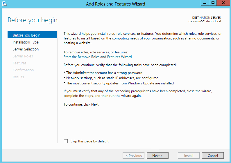
  • Open Server Manager and click Add Roles

wsus1

  • Select Role based or feature-based installation

wsus2

  • Select your destination server

wsus3

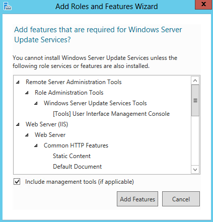
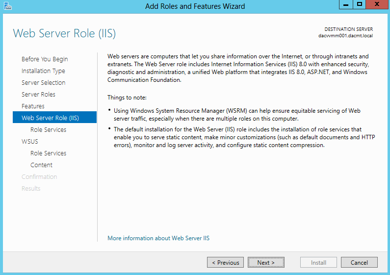
  • Put in tick in Windows Server Update Services. It will automatically tick IIS as well

wsus4

  • Accept the default feature install

wsus5

  • Make sure you also tick .NET Framework 3.5 Features

wsus6

  • Click Next on Web Server Role (IIS)

wsus7

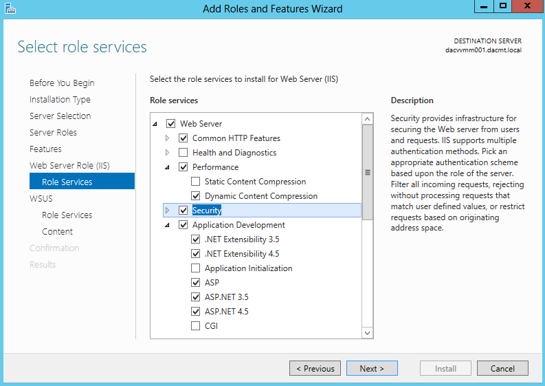
  • On Select Role Services you will need the following
  • Performance > Dynamic Content Compression
  • Security > Windows Authentication
  • Application Development > All ASP’s selected
  • Management Tools > IIS6 Management Compatibility

wsus8

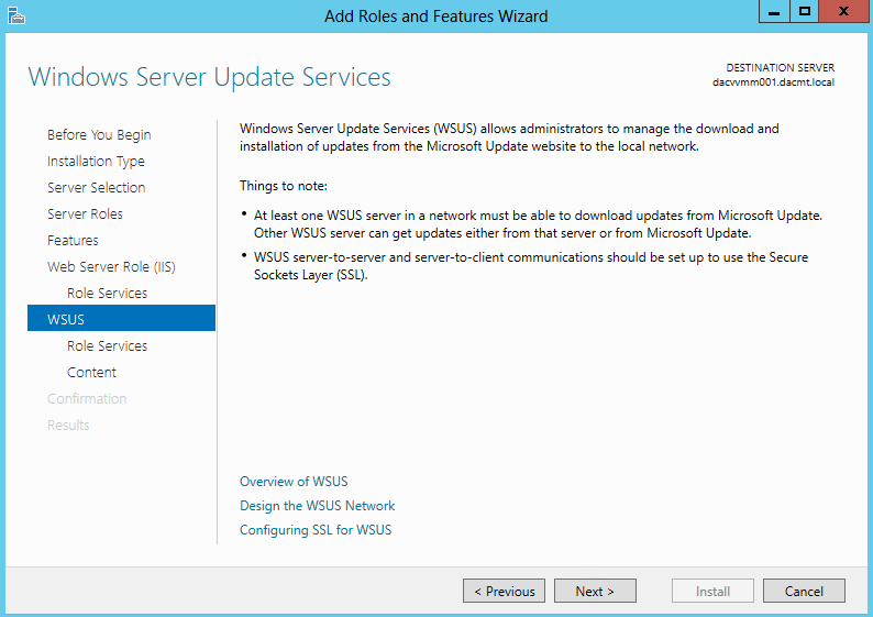
  • Click Next on the Windows Server Update Services Page

wsus9

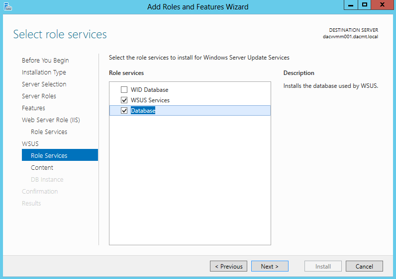
  • Untick WID Database and tick WSUS Services and Database
  • I chose Database as I have set up an instance on a separate Windows Server 2012 SQL Server and I am interested in testing the connectivity!

wsus10

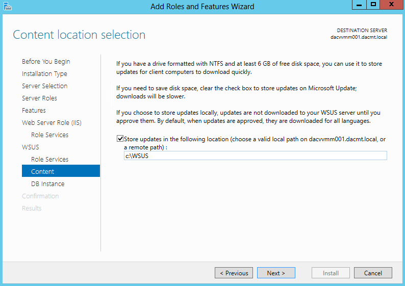
  • You will need to create a folder for the WSUS Downloads then enter the path
  • In my case I just chose c:\WSUS

wsus11

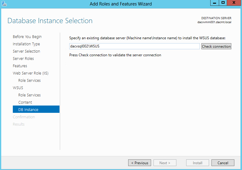
  • Put in your SQL Database Server name and Instance.
  • In my case this is dacvsql002\WSUS

wsus12

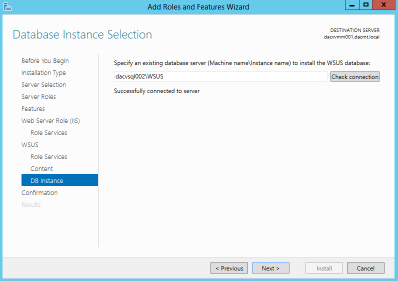
  • Click Check Connection. Hopefully it should say Successfully connected to server

wsus13

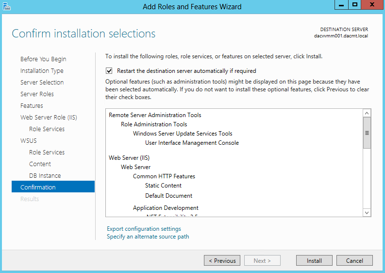
  • Check the final summary and put a tick in Restart Destination Server

wsus14

  • Click Install and wait for it to finish and you should see the below screen

wsus15

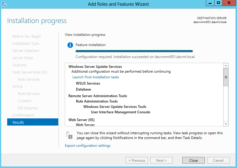
  • Note it says Further Configuration is required
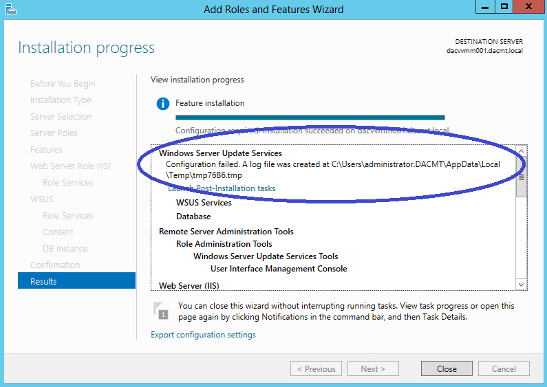
  • Click on Launch Post Installation Tasks and you will likely get an error message as per below

wsus17

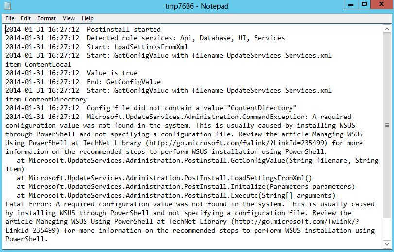
  • The Log file says

wsus18

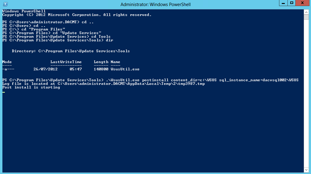
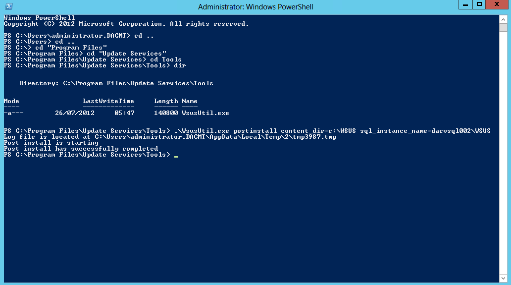
  • In order to resolve this, you need to open PowerShell as an Administrator and change to the directory where WSUSUtil is typically located in c:\Program Files\Update Services\Tools and run the following command

wsus19

  •  Once complete you should see the below screen

wsus20

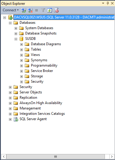
  •  I then rebooted at this point and in this time, I logged into my SQL Server to check the Database had been created under my instance dacvsql002\WSUS

WSUS48

  • When the server is back up, click the Windows Key and Q and click on Windows Update Services
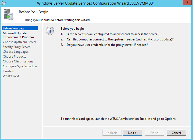
  • You can now configure WSUS by using the WSUS Configuration Wizard or you can cancel this and open the WSUS Console and configure the Options

wsus21

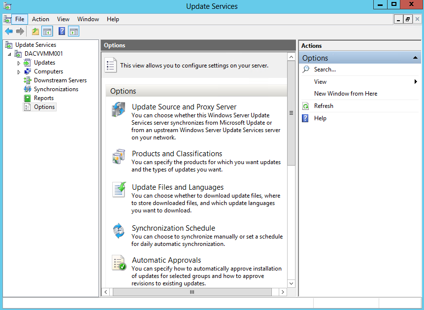
  • I cancelled and went through the options as per below
  • Click Options

wsus22

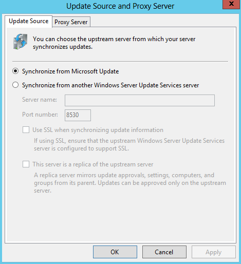
  • Update Source and Proxy Server

wsus23

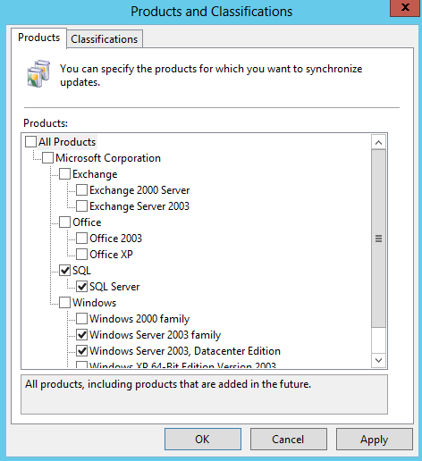
  • Products

wsus24

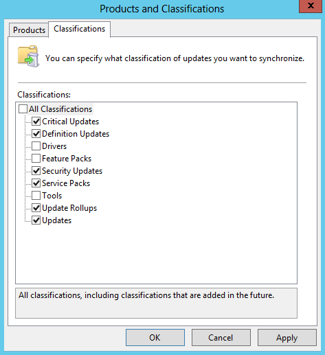
  • Classifications

wsus25

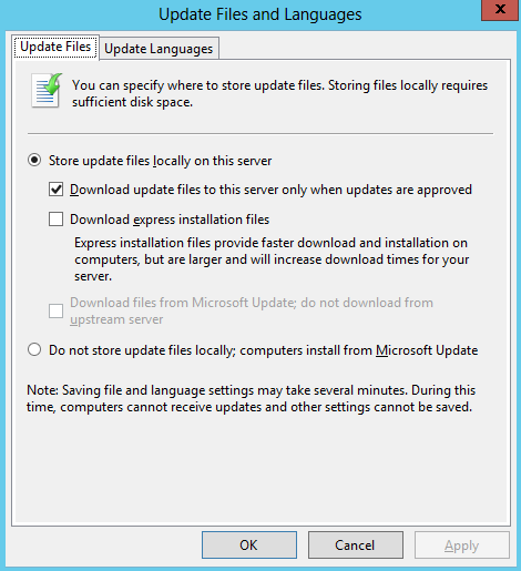
  • Update Files

wsus26

  • Update Languages

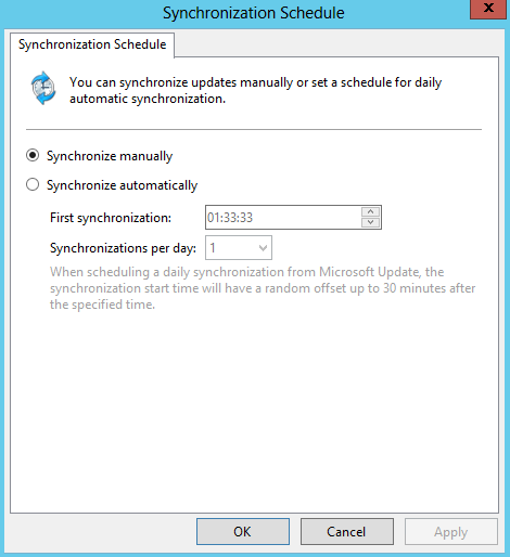
wsus27

  • Synchronisation Schedule

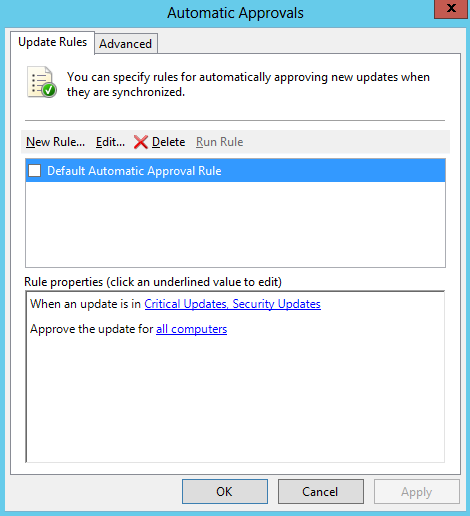
wsus28

  • Update Rules

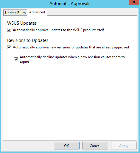
wsus29

  • Advanced

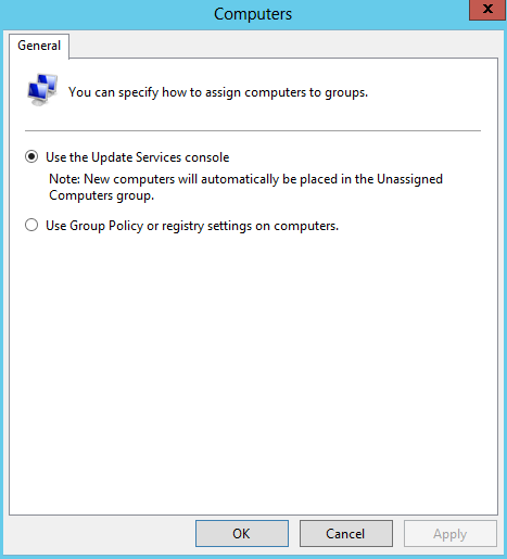
wsus30

  • Computers

wsus31

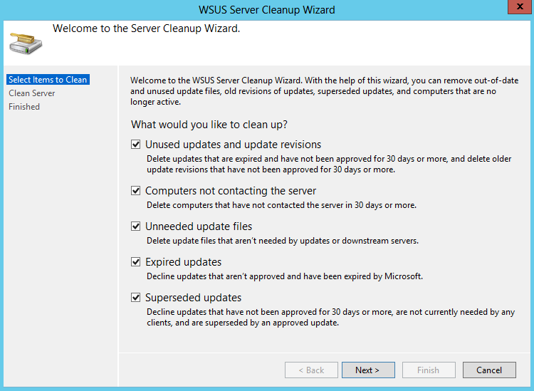
  • Server Cleanup Wizard

wsus32

  • Reporting Rollup

wsus33

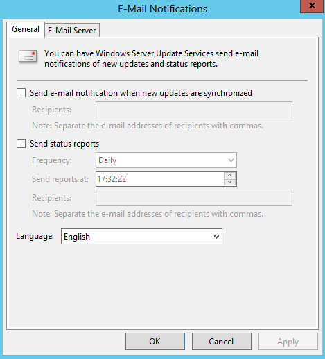
  • Email Notification

wsus34

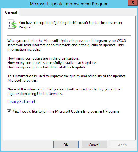
  • Microsoft Update Improvement Program

wsus35

  • Personalization

wsus36

  • And finally you have the option here to run through the configuration wizard which you have seen in an earlier screenprint

wsus21

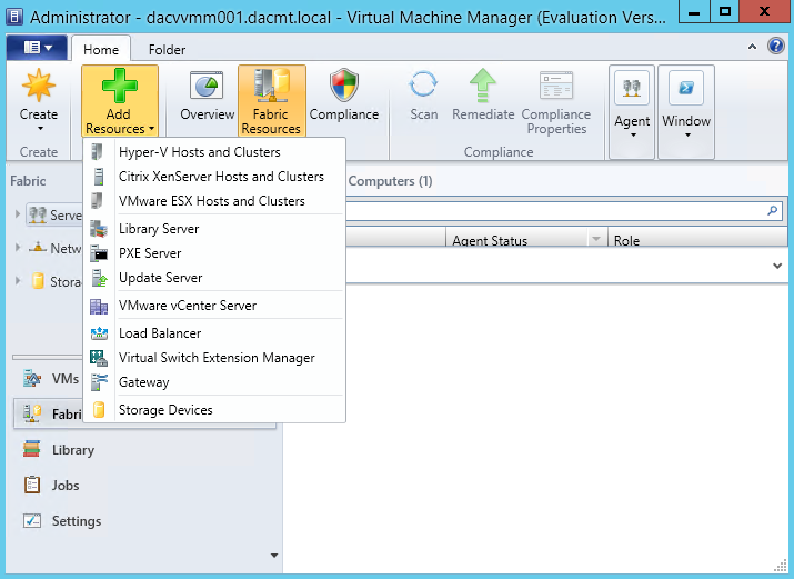
  • Now we need to add the Windows Server Update Server to VMM
  • In the VMM Console, open the fabric workspace
  • Click Add Resources > Update Server

wsus37

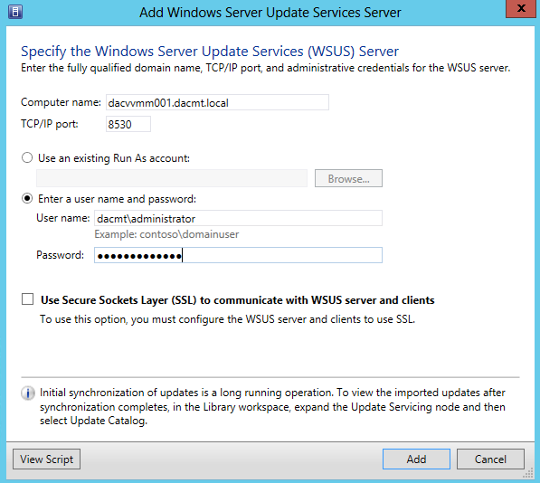
  • Add Windows Server Update Services (WSUS) Server
  • Enter in the relevant details as per below
  • It will let you know if you can’t use a User Account
  • Click Add when complete

wsus38

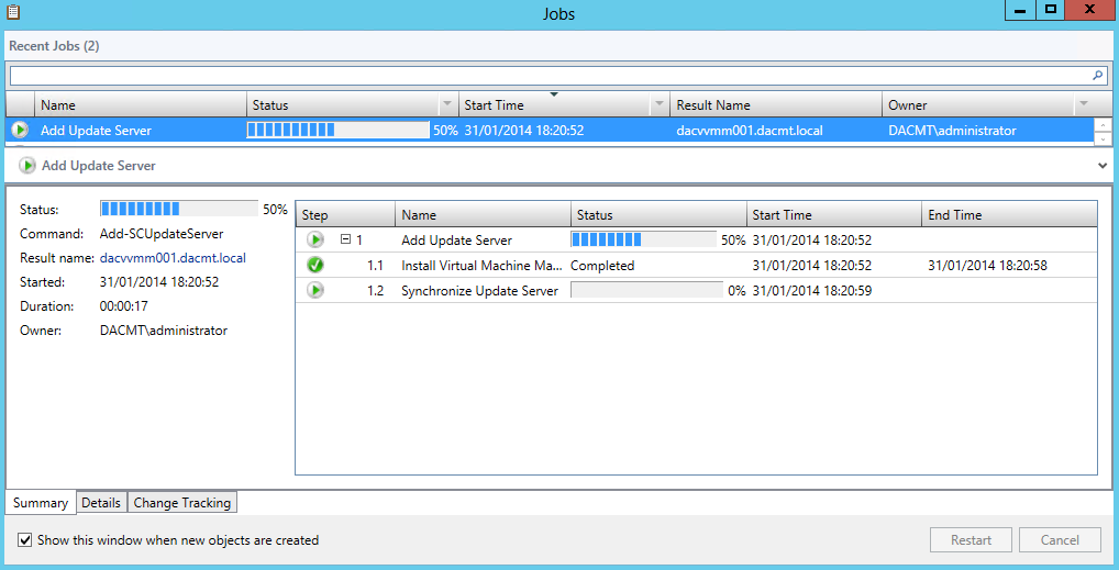
  • A job window will then pop up showing you what’s going on

wsus39

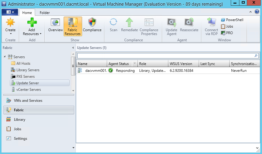
  • To verify that the WSUS Server was added to VMM successfully go to the Fabric Workspace > Expand Servers > Click Update Server.
  • The Results pane should show the WSUS Server

wsus40

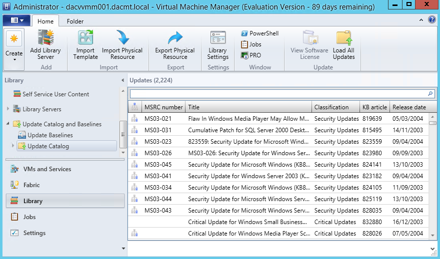
  • In the library workspace, on the library pane, expand Update Catalog and Baselines and then click Update Catalog. The results pane displays all the available updates

wsus47

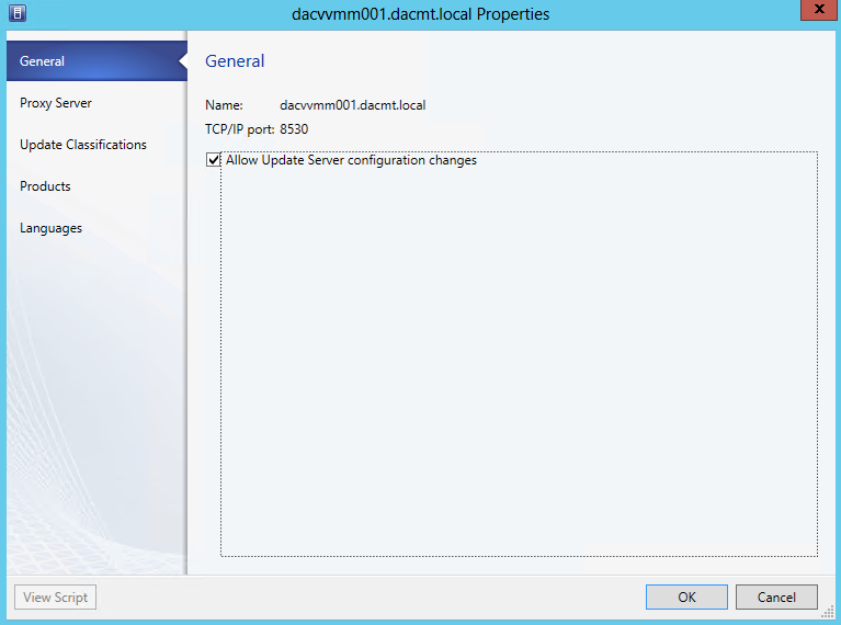
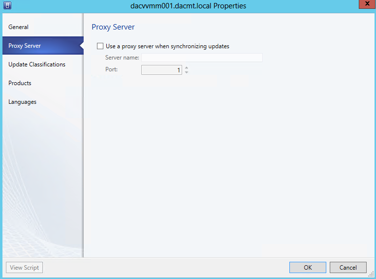
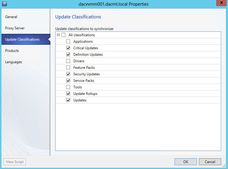
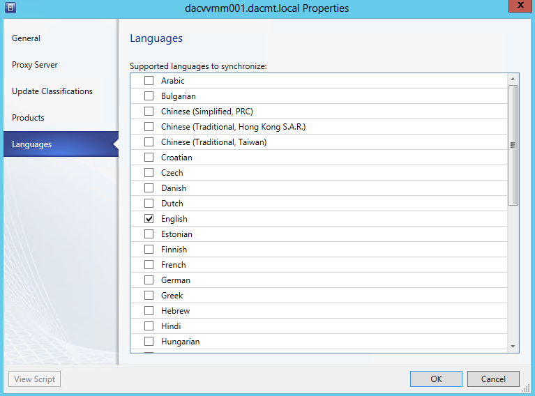
  • After you add the Update Server to VMM, you can configure a proxy server for synchronisation and change the update categories, products and supported languages that WSUS synchronises by updating the properties of the update server in VMM.
  • Open the Fabric Workspace > Expand Servers > Click Update Server
  • Right click on the Update Server in the results pane and select Properties

wsus41

  • Next you will see the Proxy Server

wsus42

  • Next you will see the Update Classification

wsus43

  • Products

wsus44

  • Languages

wsus45

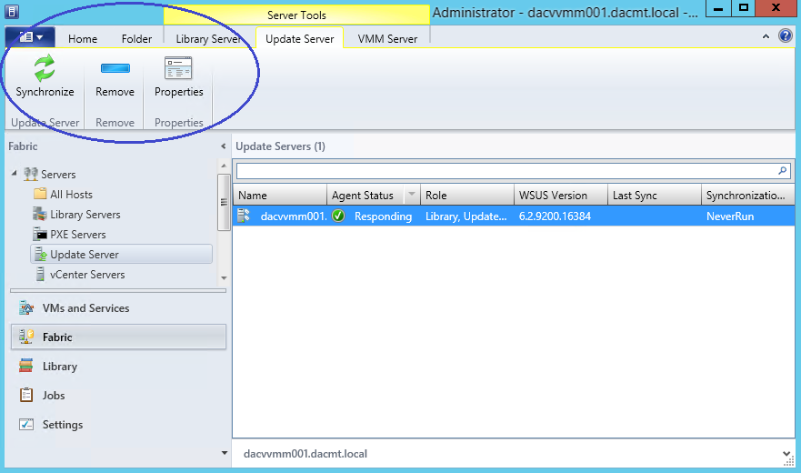
  • To manually synchronise updates in VMM, in the Fabric workspace, on the Fabric pane, expand servers and then click Update Server. You can then Synchronise. See highlighted screenprint below

wsus46

Microsoft TechNet Site for more information

http://technet.microsoft.com/en-gb/library/gg675084.aspx

VMware vCenter 5 Attributes and Tags

Capture

What are Tags?

Tags allow you to attach metadata to objects in the vSphere inventory to make these objects more sortable and searchable. A tag is a label that you can apply to objects in the vSphere inventory. When you create a tag, you assign that tag to a category.

What are Categories?

Categories allow you to group related tags together. When you define a category, you can also specify which object types its tags can be applied to and whether more than one tag in the category can be applied to an object. For example, if you wanted to tag your virtual machines by guest operating system type, you could create a category called ‘operating system’, and specify that it applies to virtual machines only and that only a single tag can be applied to a virtual machine at any time. The tags in this category could be “Windows”, “Linux”, and “Mac OS”.

Tagging replaces the custom attributes functionality found in previous versions of vCenter Server. If you have existing custom attributes, you can convert them into tags.

Migrate Custom Attributes to Tags

Tags replace the custom attributes functionality found in previous versions of vSphere. If you have existing custom attributes, you can migrate them to tags.

During the migration

  • The custom attribute names are converted to categories.
  • Custom attribute values are converted to tag names.

Procedure

  • In the vSphere Web Client object navigator, browse to Home
  • Click Tags
  • Click Convert Custom Attributes

Attributes1

  • Select the Custom Attributes you want to migrate

Attributes2

  • Create Tag Categories
  • You can change the Category Name
  • Choose the Cardinality. For example, if you wanted to tag your virtual machines by Function, you could create a category called ‘Function’, and specify that it applies to virtual machines only and that only a single or multiple tag can be applied to a virtual machine at any time. The tags in this category could be “Application”, “Database”, “Active Directory”, “DNS” and “Web”.
  • In my case, I may want to assign 2 Functions to one VM so I will choose Many Tags per object. E.g Active Directory and DNS Server
  • Choose the Associable Object Types which could be anything from Datacenter, Cluster, Datastore or All Objects. In this case I would choose VM which you can see if you scroll down on this option

Attributes4

  • Next Create Tags. Check you are happy with the Tag name

Attributes5

  • You are now ready to complete. Click Finish

Attributes6

  • Now if you click on Tags > Items, you should see the Migrated Custom Attribute

Attributes7