What’s new in vSphere 5.5

info_new_icon

What’s new in vSphere 5.5

I needed to go through these after realising my certifications were due to expire. I was able to take the VCP5-DCV Delta Exam (VCP550D) exam with Pearson Vue which is a little cheaper for those of you with existing qualifications. See the VMware site and log into your myvmware account to check the status of your existing qualifications.

A brief summary with key points on all features

  • Hot-Pluggable PCIe SSD Devices

PCIe stands for Peripheral Component Interconnect Express. These high performance Solid State Drives can be used for local storage in ESXi. The ability to hot add has always been there with SAS and SATA and is now expanded to support SSDs. Being able to provide this functionality is of great benefit to Administrators in reducing downtime to a host system in the event of a disk failure or even to be able to add an SSD drive. PCIe is a serial based technology which means information can be sent over the bus in 2 directions at once. Each lane in PCIe can transmit in both directions at the same time. Standard PCI is parallel based technology which means all data goes in one directions around a loop. Bandwidth is not shared the same way in PCIe opposed to PCI so there is less bus congestion.

Reliable Memory Technology

This is a CPU Hardware feature that ESXi can use to place the VMkernel on a region of memory which is reported as being more reliable. ESXi runs directly in memory therefore protecting it and reducing the risk of memory errors whilst increasing resiliency will provide this protection. Hostd, Initial Thread and Watchdog are also protected. The vmware-hostd management service is the main communication channel between ESX/ESXi hosts and VMkernel. The vmware-watchdog process watches over hostd and restarts it if it detects that hostd is no longer running.

Enhancements to CPU C-States

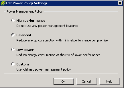
In vSphere 5.1 and earlier, the balanced policy for host power management leveraged only the performance state (P-state), which kept the processor running at a lower frequency and voltage. In vSphere 5.5, the deep processor power state (C-state) also is used, providing additional power savings. Another potential benefit of reduced power consumption is with inherent increased performance, because turbo mode frequencies on Intel chipsets can be reached more quickly while other CPU cores in the physical package are in deep C-states.
vsphere5.5

Virtual Machine Compatibility with VMware ESXi 5.5

  • LSI SAS support for Oracle Solaris 11 OS
  • Enablement for new CPU architectures
  • New advanced host controller interface (AHCI) This new virtual-SATA controller supports both virtual disks and CD-ROM devices that can
    connect up to 30 devices per controller, with a total of four controllers
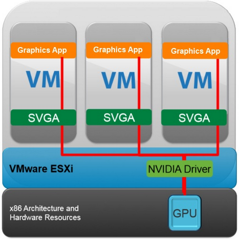
  • Hardware-accelerated 3D graphics – (vSGA) Virtual shared graphics acceleration (vSGA) support inside of a virtual machine. The existing support was limited to only NVIDIA-based GPUs. With vSphere 5.5, vSGA support has been expanded to include both NVIDIA- and AMD-based GPUs
vsphere5.5vsga

  • There are three supported rendering modes for a virtual machine configured with a vSGA: automatic, hardware and software accessed by editing the settings of a VM

Graphics Acceleration for Linux Guests

VMware is the first to develop a new guest driver that accelerates the entire Linux graphics stack for modern Linux distributions. This means that any modern GNU/Linux distribution can package the VMware guest driver and provide out-of-the-box support for accelerated graphics without any additional tools or package installation

vCenter Single Sign-On

The following vCenter Single Sign-On enhancements have been made.

  • Simplified deployment – A single installation model for customers of all sizes is now offered.
  • Enhanced Microsoft Active Directory integration – The addition of native Active Directory support enables cross-domain authentication with one and two-way trusts common in multidomain environments.
  • Built from the ground up, this architecture removes the requirement of a database and now delivers a multimaster authentication solution with built-in replication and support for multiple tenants.

vSphere Web Client

  • Full client support for Mac OS X is now available in the
    vSphere Web Client.
  • Administrators now can drag and drop objects from the center panel onto the vSphere inventory, enabling them to quickly perform bulk actions
  • Administrators can now select properties on a list of displayed objects and selected filters to meet specific search criteria
  • Recent Items. Similar to what you find on Windows desktops , this feature allows you to go back to recently accessed objects

vCenter Server Appliance

The previous embedded database had certain limitations which caused it’s adoption to be less widely taken up. The vCenter Server Appliance addresses this with a re-engineered, embedded vPostgres database that can now support as many as 100 vSphere hosts or 3,000 virtual machines (with appropriate sizing)

vSphere App HA

In earlier versions App HA used virtual machine monitoring, which checks for
the presence of “heartbeats” from VMware Tools as well as I/O activity from the virtual machine. In vSphere 5.5, VMware has introduced vSphere App HA. This new feature works in conjunction with vSphere HA host monitoring and virtual
machine monitoring to further improve application uptime. vSphere App HA can be configured to restart an application service when an issue is detected. It is possible to protect several commonly used, off-the-shelf applications. vSphere HA can also reset the virtual machine if the application fails to restart.

vSphere App HA

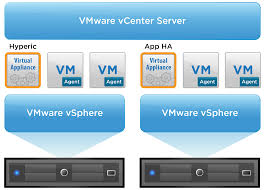
vSphere App HA uses VMware vFabric Hyperic to monitor applications. VMware vFabric Hyperic is an agent-based monitoring system that automatically collects metrics on the performance and availability of hardware resources, operating systems, middleware and applications in physical, virtualized and cloud environments. It requires the provisioning of 2 appliances

  • vSphere App HA virtual appliance stores and manages vSphere App HA policies.
  • vFabric Hyperic monitors applications and enforces vSphere App HA policies
  • Hyperic agents then need to be installed in the virtual machines containing applications that will be protected by vSphere App HA
  • Includes policies to manage timings and resetting options
vspherehypric

vSphere HA Compatibility with DRS Anti-Affinity Rules

vSphere HA will now obey DRS anti-affinity rules when restarting virtual machines.  If you have anti-affinity rules defined in DRS that keep selected virtual machines on separate hosts, VMware HA will now keep to those rules when restarting virtual machines following a host failure

vSphere Data Protection

  • Direct-to-host emergency restore: vSphere Data Protection can be used to restore a virtual machine directly to a vSphere host without the need for vCenter Server and vSphere Web Client. This is especially helpful when using vSphere Data Protection to protect vCenter Server.
  • Backup and restore of individual virtual machine hard disks (.vmdk files): Individual .vmdk files can be selected for backup and restore operations.
  • Replication to EMC Avamar: vSphere Data Protection replicates backup data to EMC Avamar to provide offsite backup data storage for disaster recovery.
  • Flexible storage placement: When deploying vSphere Data Protection, separate datastores can be selected for the OS partition and backup data partition of the virtual appliance.
  • Mounting of existing backup data storage to new appliance: An existing vSphere Data Protection backup data partition can be mounted to a new vSphere Data Protection virtual appliance during deployment.
  • Scheduling granularity: Backup and replication jobs can be scheduled at specific times; for example. Backup Job 1 at 8:45 p.m., Backup Job 2 at 11:30 p.m., and Replication Job 1 at 2:15 a.m.

vSphere Big Data Extensions (BDE)

BDE is a new addition in vSphere 5.5 for VMware vSphere Enterprise Edition
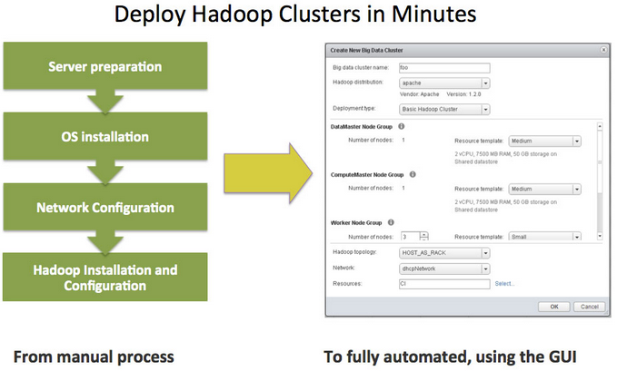
and VMware vSphere Enterprise Plus Edition. BDE is a tool that enables administrators to deploy and manage Hadoop clusters on vSphere. BDE is
based on technology from Project Serengeti, the VMware open-source virtual Hadoop management tool.

  • Creates, deletes, starts, stops and resizes clusters
  • Controls resource usage of Hadoop clusters
  • Specifies physical server topology information
  • Manages the Hadoop distributions available to BDE users
  • Automatically scales clusters based on available resources and in response to other workloads on the vSphere cluster
  • Hadoop clusters can be protected easily using vSphere HA and VMware vSphere Fault Tolerance
hadoop

Support for 62TB VMDK

The previous limit was 2TB—512 bytes. The new limit is 62TB. The maximum size of a virtual Raw Device Mapping (RDM) is also increasing, from 2TB—512 bytes to 62TB. Virtual machine snapshots also support this new size for delta
disks that are created when a snapshot is taken of the virtual machine.

Microsoft Cluster Service (MSCS)

  • Microsoft Windows 2012
  • Round-robin path policy for shared storage. changes were made concerning the SCSI locking mechanism used by MSCS when a failover of services occurs. New path policy, changes have been implemented that make it irrelevant which path is used to place the SCSI reservation; any path can free the reservation.
  • iSCSI protocol for shared storage
  • Fibre Channel over Ethernet (FCoE) protocol for shared storage

16GB E2E FC Support

In vSphere 5.5, VMware introduces 16Gb end-to-end FC support. Both the HBAs and array controllers can run at 16Gb as long as the FC switch between the initiator and target supports it.

PDL AutoRemove

Permanent device loss (PDL) is a situation which occurs when a disk device either fails or is removed from the vSphere host in an uncontrolled way. PDL detects if a disk device has been permanently removed that is, the device will not return based on SCSI sense codes. When the device enters this PDL state, the vSphere host can take action to prevent directing any further, unnecessary I/O to this device. This alleviates other conditions that might arise on the host as a result of this unnecessary I/O. The PDL feature automatically removes a device from a host when it enters a PDL state. Because vSphere hosts have a limit of 255 disk devices per host, a device that is in a PDL state can no longer accept I/O but can still occupy one of the available disk device spaces. Therefore, it is better to remove the device from the host.
PDL AutoRemove occurs only if there are no open handles left on the device. The auto-remove takes place when the last handle on the device closes. If the device recovers, or if it is re-added after having been inadvertently removed, it will be treated as a new device.

vSphere Replication

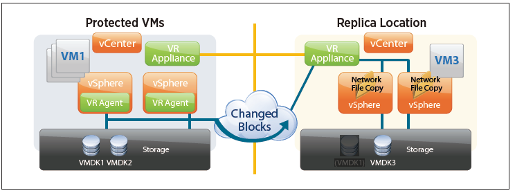
At the primary site, migrations now move the persistent state files that contain pointers to the changed blocks along with the VMDKs in the virtual machine’s home directory, thereby removing the need for a full synchronization. This means that replicated virtual machines can now be moved between datastores, by vSphere Storage vMotion or vSphere Storage DRS, without incurring a penalty on the replication. The retention of the .psf means that the virtual machine can be brought to the new datastore or directory while retaining its current replication data and can continue with the procedure and with the “fast suspend/resume” operation of moving an individual VMDK.
replication

A new feature is introduced in vSphere 5.5 that enables retention of historical points in time. The old redo logs are not discarded; instead, they are retained and cleaned up on a schedule according to the MPIT retention policy.

VAAI UNMAP Improvements

vSphere 5.5 introduces a new and simpler VAAI UNMAP/Reclaim command:

  • esxcli storage vmfs unmap
  • The ability to specify the reclaim size in blocks rather than as a percentage value; dead space can now be reclaimed in increments rather than all at once

VMFS Heap Improvements

In vSphere 5.5, VMware introduces a much improved heap eviction process, so there is no need for the larger heap size, which consumes memory. vSphere 5.5, with a maximum of 256MB of heap, enables vSphere hosts to access all address space of a 64TB VMFS

vSphere Flash Read Cache

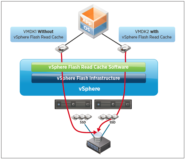
vSphere Flash Read Cache enables the pooling of multiple Flash-based devices into a single consumable vSphere construct called vSphere Flash Resource, which is consumed and managed in the same way as CPU and memory are done today in vSphere.
The vSphere Flash Read Cache infrastructure is responsible for integrating the vSphere hosts’ locally attached Flash-based devices into the vSphere storage stack. This integration delivers a Flash management platform that enables the pooling of Flash-based devices into a vSphere Flash Resource.
Flashcache

Link Aggregation Protocol Enhancements

  • Comprehensive load-balancing algorithm support – 22 new hashing algorithm options are available. For example, source and destination IP address and VLAN field can be used as the input for the hashing algorithm.
  • Support for multiple link aggregation groups (LAGs) – 64 LAGs per host and 64 LAGs per VMware vSphere VDS.
  • Because LACP configuration is applied per host, this can be very time consuming for large deployments. In this release, new workflows to configure LACP across a large number of hosts are made available through templates.

Traffic Filtering enhancements

The vSphere Distributed Switch now supports packet classification and filtering based on MAC SA and DA qualifiers, traffic type qualifiers (i.e. vMotion, Management, FT), and IP qualifiers (i.e. protocol, IP SA, IP DA, and port number).

Quality of Service Tagging

Two types of Quality of Service (QoS) marking/tagging common in networking are 802.1p Class of Service

  • (CoS) Class of Service applied on Ethernet/layer 2 packets
  • (DSCP) Differentiated Service Code Point, applied on IP packets. In vSphere 5.5, the DSCP marking support enables users to insert tags in the IP header. IP header–level tagging helps in layer 3 environments, where physical routers function better with an IP header tag than with an Ethernet header tag.

SR-IOV Enhancements

Single-root I/O virtualization (SR-IOV) is a standard that enables one PCI Express (PCIe) adapter to be presented as multiple, separate logical devices to virtual machines.

  • A new capability is introduced that enables users to communicate the port group properties defined on the vSphere standard switch (VSS) or VDS to the virtual functions. The new control path through VSS and VDS communicates the port group–specific properties to the virtual functions. For example, if promiscuous mode is enabled in a port group, that configuration is then passed to virtual functions, and the virtual machines connected to the port group will receive traffic from other virtual machines.

Enhanced Host Level Performance

  • An enhanced host-level packet capture tool is introduced. The packet capture tool is equivalent to the command-line tcpdump tool available on the Linux platform.
  • This tool is part of the vSphere platform and can be accessed through the vSphere host cmd prompt
  • Can capture dropped packets
  • Can trace the path of a packet with time stamp details
  • Can capture traffic on VSS and VDS
  • Captures packets at the following levels
    ––Uplink
    ––Virtual switch port
    ––vNIC

40Gb NIC Support

vSphere 5.5 provides support for 40Gb NICs.  In 5.5 the functionality is limited to the Mellanox ConnectX-3 VPI adapters configured in Ethernet mode.

Maximums

  • 320 physical CPUs
  • 4TB Memory
  • 16 Numa nodes
  • 4906 vCPUs per ESXi host
Excel 2010: Not enough system resources to display completely

excelicon

The Problem

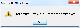
When opening an Excel file or running calculations within an Excel file, you may get the following error

excel2010

This is a very miscellaneous error and one that is not easily solved sometimes but here are a few things to try

  1. If you have any COM add-ins installed, un-install them unless they are absolutely required or just untick them to test.  COM add-ins are a special type of add-in written in machine language. They are often installed without explicit approval.  COM add-ins are often reported as causing memory problems
  2. To see if you have multiple sessions open, press CTL-ALT-DELETE and check how any Excel applications are running.  There should be just one running. If a new Excel session opens each time you double click on a workbook, try unchecking the Excel Option “Ignore other applications” if it is checked on the Options General tab.
  3. Excel may think your worksheets are larger than you do.  This can consume a lot of memory. Normally your scroll area controlled by the scroll bars is very small.  However, sometimes Excel thinks there are cells well below your used range. One way is to check where Excel thinks the last cell is located.  Do this by pressing CTRL+SHIFT+END.  If it well below your used range, then select all “unused” columns in this range and delete them. Then select all unused rows in this range and delete them .  Then close and re-open Excel
  4. Install the latest upgrades to your version of Office.
  5. You can try deleting temp files. There is a nice piece of software called Temp File Deleter https://www.add-ins.com/temp_file_deleter.htm
  6. If you are using Google Desktop Search, un-install it.  Google Desktop Search appears to be a memory hog and has been reported to interfere with Microsoft Excel.  Specifically, it installs a COM add-in that monitors every action in Excel so that it can index it which can slow everything down
  7. If you are using Excel 2010-2013, click File, Options, Advanced, and go to the General section. Check if you have an alternate startup folder and check its content, and remove anything you do not need
  8. Check and see if you have an un-needed add-in or workbook in your XLSTART folder. This folder may vary location wise depending on local and roaming profiles
  9. Delete your XLB file. (Search for *.XLB) It can become corrupt but cause no visible problems. If corrupt it can consume lots of memory. Excel will recreate, but button customization will be lost.  This is a file where Excel stores its toolbar settings.   To delete it, use the XLB File Deleter which is a free product. There have been reports that doing this will solve problems.
  10. Your printer or its driver may be causing the problem.  HP printers have a history of causing a memory problem with Excel.  We do not know if HP fixed the problem and it may still be around or surfacing again.  Change your default printer if you have other printers available as a test
  11. Use of macros that do very extensive file creating, data manipulation, and graphing have been known to cause memory leak problems. Such macros are ones that typically run for 30 minutes or longer.
  12. If you have Track Changes turned on in Excel, turn off Track Changes as it uses a fair amount of memory.  The default is Off.
  13. Turn off AutoRecovery, as this takes up Excel memory.  However, have a backup if you do. To turn off AuoRecovery go to File,Options, Save. Uncheck Auto Recovery
  14. Problems in your application data folder for Excel can be the cause.  The folder is typically “c:\documents and settings\%username%\application data\microsoft\excel”.  This is a hidden folder, so set your Explorer options to show hidden folders. After backing up, rename or delete this folder and its subfolders.  Reboot the machine and open Excel.  Excel will recreate the folder and needed contents.
  15. Run the following 2 commands. “C:\Program Files\Microsoft Office\OFFICE11\excel.exe” /unregserver and “C:\Program Files\Microsoft Office\OFFICE11\excel.exe” /regserver. (Change the number 11 to 12 for Excel 2007, 14 for Excel 2010 and 15 for Excel 2013) These commands remove most of the Excel registry entries and then resets them.  However, they do leave some residual settings.
  16. A more extensive way to clean the registry is to rename the Excel registry key and let Excel recreate it. It depends on the version of Excel.  First, close Excel.  Then do Run, Regedit and go to the Excel registry key.  It will be “HKEY_CURRENT_USER\Software\Microsoft\Office\%version_number%\Excel”
    where %version_number% is 11 for Excel 2003, 12 for Excel 2007, 14 for Excel 2010 and 15 for Excel 2013. Rename this to OldExcel (this will back it up). Then re-open Excel.  Excel will rebuild the registry entry.  You will need to manually install any needed add-ins
  17. It may be the case that the Server or PC that Excel is running on needs more memory or that you need to close other running apps which may be interfering with Excel or taking up more memory that Excel needs
  18. Try opening Excel in Safe Mode. For example C:\Program Files\Microsoft Office\Office\Excel.exe /s
  19. Try opening Excel whilst holding the shift key down to stop any macros from executing or type Click Start, Run, “C:\Program Files\Microsoft Office\Office\Excel.exe” /Automation


Using HttpWatch to check websites

images2

What is HttpWatch?

HttpWatch is an HTTP sniffer for IE, Firefox, iPhone & iPad that provides new insights into how your website loads and performs. All web applications make extensive use of the HTTP protocol (or HTTPS for secure sites). Even simple web pages require the use of multiple HTTP requests to download HTML, graphics and javascript. The ability to view the HTTP interaction between the browser and web site is crucial to these areas of web development.

We needed to use this software to see what underlying sites a main site was linking to as we used Kerio Web Proxy which was blocking some websites we couldn’t see and needed to add to a whitelist.

http://www.httpwatch.com/

HttpWatch Features

  • Easily monitor HTTPS, HTTP and SPDY without using proxies or changing network settings
  • Supports IE/Firefox on Windows and iOS app for iPhone / iPad
  • Real-time page and request level time charts
  • Users and customers can send you log files for free
  • Automatically detects potential  configuration, performance and security related issues on your web server
  • Can be automated using most programming languages, e.g. C#, Ruby, Javascript, Ruby
  • Provides millisecond accurate timings

HttpWatch has two components; a plug-in used to collect, view and save HTTP traffic within IE or Firefox, and a standalone log file viewer know as HttpWatch Studio.

How can HttpWatch Help?

  • HttpWatch integrates with Internet Explorer and Firefox browsers to show you exactly what HTTP traffic is triggered when you access a web page. If you access a site that uses secure HTTPS connections, HttpWatch automatically displays the decrypted form of the network traffic.
  • Conventional network monitoring tools just display low level data captured from the network. In contrast, HttpWatch has been optimized for displaying HTTP traffic and allows you to quickly see the values of headers, cookies and query strings.

HttpWatch also supports non-interactive examination of HTTP data. When log files are saved, a complete record of the HTTP traffic is saved in a compact file. You can even examine log files that your customers and suppliers have recorded using the free basic edition.

How to use HttpWatch

  • Install from the website listed above
  • If you are not able to access HttpWatch using one of the methods below please check that all HttpWatch entries are enabled in the Tools->Add-ons window of each browser/.
  • Also, with IE it may also be necessary to restart Windows before the HttpWatch plug-in is correctly installed
  • The HttpWatch plug-in can be displayed in the lower part of the Internet Explorer (IE) or Firefox window by using one of the following methods:
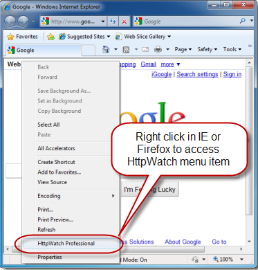
  • Right click in a webpage and select HttpWatch Basic or HttpWatchProfessional

httpwatch1

or

  • Use the shortcut key Shift+F2
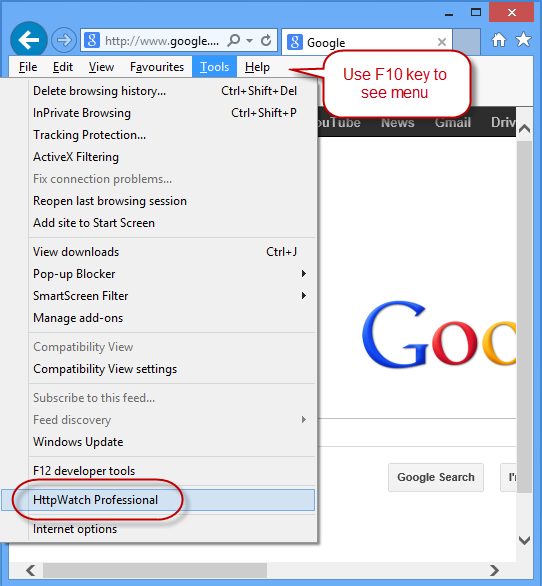
  • Use the HttpWatch menu item on the Tools menu. In later versions of IE and Firefox you may need to press F10 to display the menu:

httpwatch2

  •  Once you have HttpWatch displayed in the browser, press the Record button to start recording HTTP requests.
  • If you are using the free Basic Edition then extended HTTP information is only displayed for sites in the Alexa Top 20 or httpwatch.com
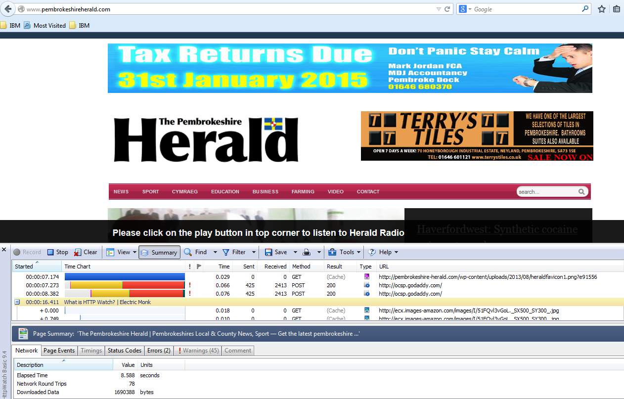
  • As an example I have tested http://pembrokeherald.com

httpwatch3

  •  You can then see all the underlying websites

Logon script to copy 2 folders into a user’s Roaming Profile

Script

The Task

Our users are logging into several Terminal Server Farms where they are running a TM1 application client which connects to the main TM1 Server. On opening the client it is meant to put 2 folders in their profile under the AppData folder. This is a folder called Applix which also contains another folder called TM1.

We have roaming profiles where we have a profile drive and a home drive and the AppData folder is redirected to the user’s Home Drive. It seems that this application does not cope well with creating the Applix folder on the redirected Home Folder location

However we have found it works fine when you have a straight roaming profile with no redirected folders!

So what do we need to happen?

  1. A user logs on to a Terminal Server Farm
  2. At logon a GPO containing a PowerShell script to do this task will run
  3. The script will test that the folder path exists first \\ServerXYZ\Home\Username\AppData\Roaming and if it does, it will do nothing
  4. If the path doesn’t exist, it will put a folder called Applix in the following path \\ServerXYZ\Home\Username\AppData\Roaming
  5. Note, we put the Applix folder on the Terminal Servers as C:\Applix and the script picks this up for copying from this location

The PowerShell Script

if (!(Test-path “\\ServerXYZ\Home\$env:USERNAME\AppData\Roaming\Applix”))
{
Copy-Item -path “C:\Applix” -Recurse -Destination “\\ServerXYZ\Home\$env:USERNAME\AppData\Roaming\Applix” -Container
}


ActiveSync on Microsoft Exchange 2010 +

ActiveSync

ActiveSync

Exchange ActiveSync is a Microsoft Exchange synchronization protocol that’s optimized to work together with high-latency and low-bandwidth networks. The protocol, based on HTTP and XML, lets mobile phones access an organization’s information on a server that’s running Microsoft Exchange. Exchange ActiveSync enables mobile phone users to access their e-mail, calendar, contacts, and tasks and to continue to be able to access this information while they’re working offline When you allow mobile phones or other mobile devices to synchronize with your Exchange 2010 server, you allow sensitive corporate information to be stored on small, portable devices that can be easily lost or stolen. Before you deploy Exchange ActiveSync, we recommend that you familiarize yourself with the various security settings you can configure to keep your corporate information safe. You can configure an authentication method for Exchange ActiveSync, deploy Exchange ActiveSync mailbox policies, and use remote device wipe to remove personal and corporate data from a lost or stolen mobile phone

Things to have setup

In order to be able to receive external email into your internal Exchange server, you will need to have an external domain which is setup to forward your MX and A records to your internal environment. As an example I have a domain called electricmonk.org.uk which I use as my test external domain for this blog. I had to ask my domain company to setup the following records and forward them to my routers external address.

  • MX mail.electricmonk.org.uk
  • A mail.electricmonk.org.uk
  • A owa.electricmonk.org.uk
  • A autodiscover.electricmonk.org.uk

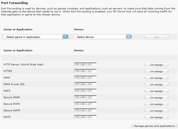
These records will then hit my router then depending on your routers setup, you will need to forward the relevant mail ports to your Exchange Server.

  • POP3 = 110
  • IMAP = 143
  • SMTP = 25
  • HTTP = 80
  • HTTPS = 443
  • Secure SMTP = 465
  • Secure POP3 = 995
  • Secure IMAP = 585
  • IMAP4 over SSL = 995
  • Exchange (SMTP-MSA) =587

This is my BT Router Port Forwarding setup set to forward these ports to my mail server on my internal network

Exchange31

Features in Exchange ActiveSync

Exchange ActiveSync provides the following:

  • Support for HTML messages
  • Support for follow-up flags
  • Conversation grouping of e-mail messages
  • Ability to synchronize or not synchronize an entire conversation
  • Synchronization of SMS messages with a user’s Exchange mailbox
  • Support for viewing of message reply status
  • Support for fast message retrieval
  • Meeting attendee information
  • Enhanced Exchange Search
  • PIN reset
  • Enhanced device security through password policies
  • Autodiscover for over-the-air provisioning
  • Support for setting auto-replies when users are away, on vacation, or out of the office
  • Support for tasks synchronization
  • Direct Push
  • Support for availability information for contacts

Exchange ActiveSync Server Security

There are several security-related tasks you can perform on a server that’s running Exchange ActiveSync. One of the most important tasks is to configure an authentication method. Exchange ActiveSync runs on a computer running Exchange 2010 that has the Client Access server role installed. This server role is installed with a default self-signed digital certificate. Although the self-signed certificate is supported for Exchange ActiveSync, it isn’t the most secure method of authentication. For additional security, consider deploying a trusted certificate from a third-party commercial certification authority (CA) or a trusted Windows public key infrastructure (PKI) certification authority.

Selecting an Authentication Method for Exchange ActiveSync

In addition to deploying a trusted digital certificate, you should consider the different authentication methods that are available for Exchange ActiveSync. By default, when the Client Access server role is installed, Exchange ActiveSync is configured to use Basic authentication with Secure Sockets Layer (SSL). To provide increased security, consider changing your authentication method to Digest authentication or Integrated Windows authentication

Exchange ActiveSync Mailbox Policies

Exchange ActiveSync for Exchange 2010 enables you to create Exchange ActiveSync mailbox policies to apply a common set of security settings to a collection of users. These settings include the following

  • Requiring a password
  • Specifying the minimum password length
  • Requiring numbers or special characters in the password
  • Designating how long a mobile phone can be inactive before the user is required to re-enter the password
  • Specifying that the mobile phone or mobile device be wiped if an incorrect password is entered more than a specific number of times

Accessing ActiveSync Policies

  • Click on Organization Configuration > Client Access then in the Action pane select Exchange ActiveSync Mailbox Policies

Exchange05

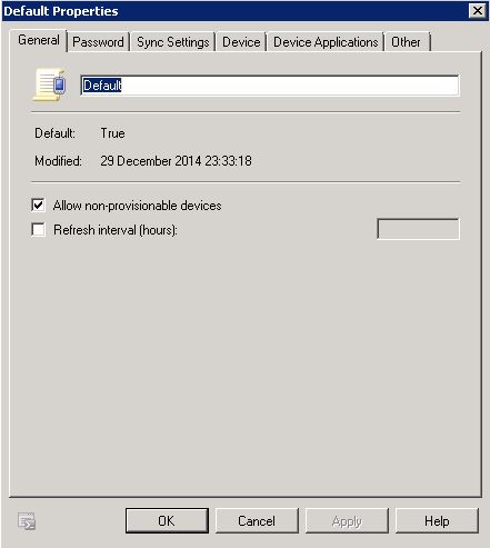
  • Right click on Default and select Properties

Exchang06

  • Allow non-provisional devices – Select this check box to allow mobile phones that can’t be provisioned automatically. These mobile phones may be unable to enforce all the Exchange ActiveSync policy settings. By selecting this box, you’re allowing these mobile phones to synchronize even though some policy settings may not be applied.
  • Refresh Interval – Select this check box to force the server to resend the policy to clients at a fixed interval defined in the number of hours between policy refresh events.
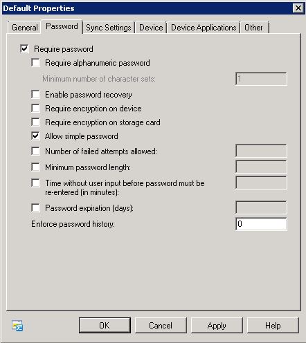
  • Click on Password

Exchange07

  • Require password – Select this checkbox to require a password for the mobile phone. If passwords are required, the following options become available.
  • Require alphanumeric password – Select this check box to specify that the mobile phone password must include non-numeric characters. Requiring non-numeric characters in passwords increases the strength of password security.
  • Minimum number of character sets – Use this text box to specify the complexity of the alphanumeric password and force users to use a number of different sets of characters from among the following: lower case letters, upper case letters, symbols and numbers.
  • Enable password recovery – Select this check box to enable password recovery for the mobile phone. Users can use Outlook Web App to look up their recovery password and unlock their mobile phone. Administrators can use the EMC to look up a user’s recovery password.
  • Require encryption on device – Select this check box to require encryption on the mobile phone. This increases security by encrypting all information on the mobile phone.
  • Require encryption on storage cards – Select this check box to require encryption on the mobile phone’s removable storage card. This increases security by encrypting all information on the storage cards for the mobile phone.
  • Allow simple password – Select this check box to allow users to lock their mobile phones with simple passwords such as 1111 or 1234. If you clear this check box, users will be required to use more secure password sequences.
  • Number of failed attempts allowed – Use this text box to limit the number of failed password attempts a mobile phone accepts before all information on the mobile phone is deleted and the mobile phone is automatically returned to the original factory settings. This reduces the chance of an unauthorized user accessing information on a lost or stolen mobile phone that has a password.
  • Minimum password length – Use this text box to specify a minimum password length for the mobile phone password. Long passwords can provide increased security. However, long passwords can decrease mobile phone usability. A moderate password length of four to six characters is recommended.
  • Time without user input before password must be re-entered (in minutes) – When a mobile phone password is required, you can use this text box to prompt the user for the password after the mobile phone has been inactive for a specified period of time. For example, if this setting is set to 15 minutes, the user must enter the mobile phone password every time that the mobile phone is idle for 15 minutes. If the mobile phone is idle for 10 minutes, the user won’t have to re-enter the password.
  • Password expiration (days) – Use this text box to force users to reset their mobile phone’s password at a given interval. The interval is set in a number of days.
  • Enforce password history – Select this check box to force the mobile phone to prevent the user from re-using their previous passwords. The number you set determines how many past passwords the user won’t be allowed to reuse.
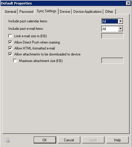
  • Next Click on Sync Settings

Exchange08

  • Include past calendar items – Use this drop-down list to select the date range of calendar items to synchronize to the mobile phone. The available options include the following: All, Two Weeks, One Month, Three Months, and Six Months. If you have to specify other options, use the Shell to configure this setting.
  • Include past e-mail items – Use this drop-down list to select the date range of e-mail items to synchronize to the mobile phone. The available options include the following: All, One Day, Three Days, One Week, Two Weeks, and One Month. If you have to specify other options, use the Shell to configure this setting.
  • Limit e-mail size to (KB) – Select this check box to limit the message size that can be downloaded to the mobile phone. After you’ve selected the check box, use the text box to specify a maximum message size, in kilobytes (KB).
  • Allow Direct Push when roaming – Select this check box to enable the mobile phone to synchronize as new items arrive when you’re roaming with your phone. You’re roaming when you’re outside your normal service area. Check with your mobile service provider to determine your normal service area. Clearing this check box forces you to manually launch synchronization when you’re roaming with the phone and data rates are traditionally higher.
  • Allow HTML-formatted e-mail – Select this check box to enable e-mail messages that are formatted in HTML to be synchronized to the mobile phone. If this check box isn’t selected, all e-mail messages will be converted to plain text before synchronization. Use of this check box doesn’t affect whether or not messages are received on the mobile phone.
  • Allow attachments to be downloaded to device – Select this check box to enable attachments to be downloaded to the mobile phone. If this check box is cleared, the name of the attachment is visible within the e-mail message but can’t be downloaded to the mobile phone.
  • Maximum attachment size (KB) – Select this check box to specify a maximum size for attachments that are downloaded to the mobile phone. After you select the check box, use the text box to enter a maximum attachment size, in KB. If this check box is selected, attachments that are larger than the specified size can’t be downloaded to the device.
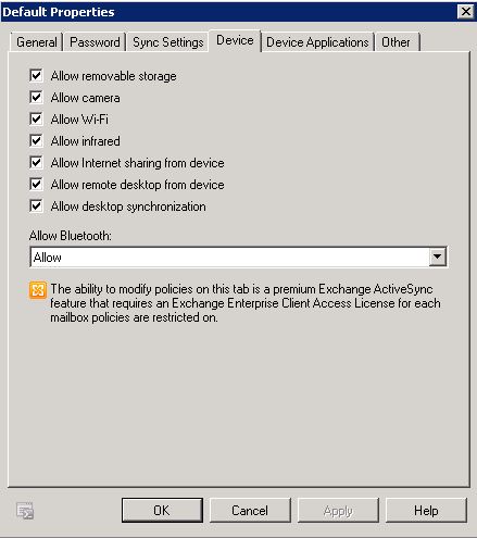
  • Next Click on Device. Use the Device tab to specify a variety of device-specific settings. All settings that you access on the Device tab of the Exchange ActiveSync policy Properties page are premium features of Exchange ActiveSync. For these features to be implemented on a mobile phone, the mailbox requires an Exchange Enterprise client access license (CAL).

Exchange09

  • Allow removable storage – Select this check box to allow storage cards to be accessed from a mobile phone. If this check box isn’t selected, storage cards can’t be accessed from a mobile phone.
  • Allow camera – Select this check box to allow the mobile phone camera to be used.
  • Allow Wi-Fi – Select this check box to allow the mobile phone to use a Wi-Fi connection for Internet access. Direct Push isn’t supported over Wi-Fi.
  • Allow infrared – Select this check box to allow the mobile phone to establish an infrared connection with other devices or computers.
  • Allow Internet sharing from device – Select this check box to allow another device to share the Internet connection of the mobile phone. Internet sharing is frequently used when the device functions as a modem for a laptop or desktop computer.
  • Allow remote desktop from device – Select this check box to allow the mobile phone to establish a remote desktop connection to another computer.
  • Allow desktop synchronization – Select this check box to allow the mobile phone to synchronize with a desktop computer through desktop ActiveSync or the Windows Mobile Device Center.
  • Allow Bluetooth – Use this drop-down list to control the Bluetooth functionality of the mobile phone. You can choose to Allow, Disable, or enable Bluetooth for Handsfree only
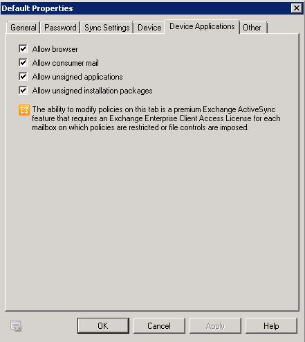
  • Click on Device Application. Use the Device Applications tab to enable or disable specific features on a mobile phone. All settings that you access on the Device Applications tab of the Exchange ActiveSync policy Properties pages are premium features of Exchange ActiveSync. For these features to be implemented on a mobile phone, the mailbox requires an Exchange Enterprise client access license (CAL).

Exchange10

  • Allow browser Select this check box to allow mobile phones to use Pocket Internet Explorer
  • Allow consumer mailSelect this check box to allow the mobile phone to access e-mail accounts other than Microsoft Exchange accounts. Consumer e-mail accounts include accounts that are accessed through POP3 and IMAP
  • Allow unsigned applications – Select this check box to allow unsigned applications to be installed on the mobile phone.
  • Allow unsigned installation packages – Select this check box to allow unsigned installation packages to be run on the mobile phone
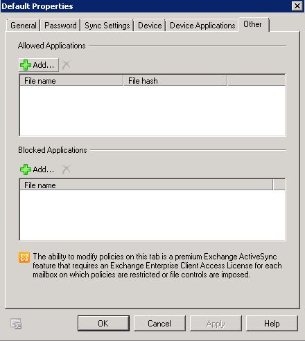
  • Click on Other. Use the Other tab to specify allowed and blocked applications. All settings that you access on the Other tab of the Exchange ActiveSync policy Properties pages are premium features of Exchange ActiveSync. For these features to be implemented on a mobile phone, the mailbox requires an Exchange Enterprise client access license (CAL).

Exchange11

  • Allowed Applications   You can add applications to or remove them from the Allowed Applications list. Allowed applications can be installed and run on the mobile phone. Click Add to add an application, and click Delete to remove an application.
  • Blocked Applications   You can add applications to or remove them from the Blocked Applications list. Blocked applications are prohibited from running on the mobile phone. Click Add to add an application, and click Delete to remove an application.

Accepted Domains

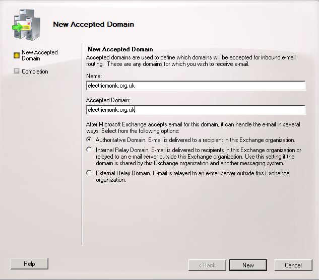
Make sure you have your accepted external domain listed here

  • Click on Organization Configuration and then click on Hub Transport
  • Click on the Accepted Domains tab and you should see your local address
  • In the Actions pane, click on New Accepted Domain
  • Put in a name for this Domain and the name itself

Exchange37

  • You should now see your domains

Exchange38

Send Connectors

  • Go to Organisation Configuration > Hub Transport
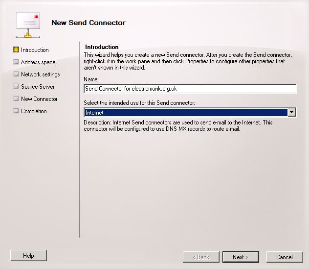
  • Click New Send Connector

Exchange39

  • Type a name and choose Internet for the intended use
  • Click Next
  • On the Address space page click Add and add in * to Address and tick Include all subdomains
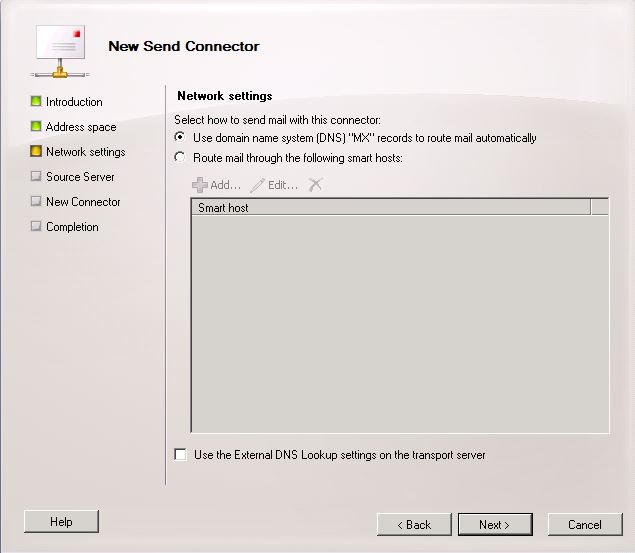
  • Keep Use Domain name system (DNS) “MX” records to route mail automatically ticked

Exchange17

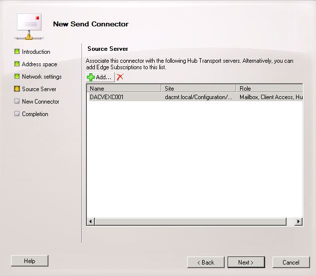
  • Check your Source Server is selected

Exchange18

  • The Summary Page will appear. Check the details and click New
  • You should now see your new Send Connector

Exchange40

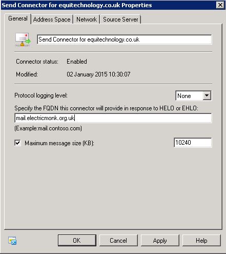
  • Double click on this Send Connector and select Properties
  • You need to put in your external domain here

Exchange32

Set up an email policy

  • Go to Organization Configuration
  • Go to Hub Transport
  • Go to E-mail Address Polices
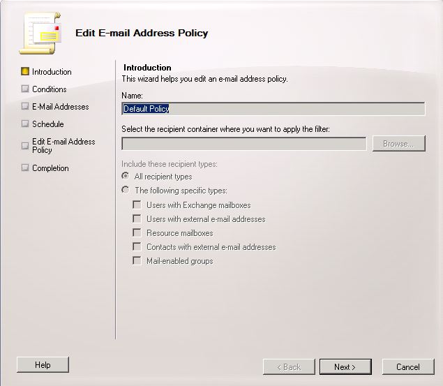
  • Click on the Default Policy
  • Click Next

Exchange34

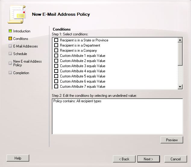
  • You are now on the New E-Mail Address Policy Page. Don’t select anything on here for now

Exchange22

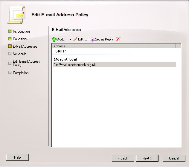
  • Click Next and you are now on the E-Mail Addresses Page
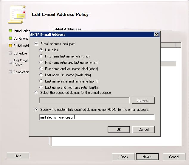
  • Click Add

Exchange35

  • Click OK

Exchange33

  • Click the %m@mail.electricmonk.org.uk and select Set as Reply
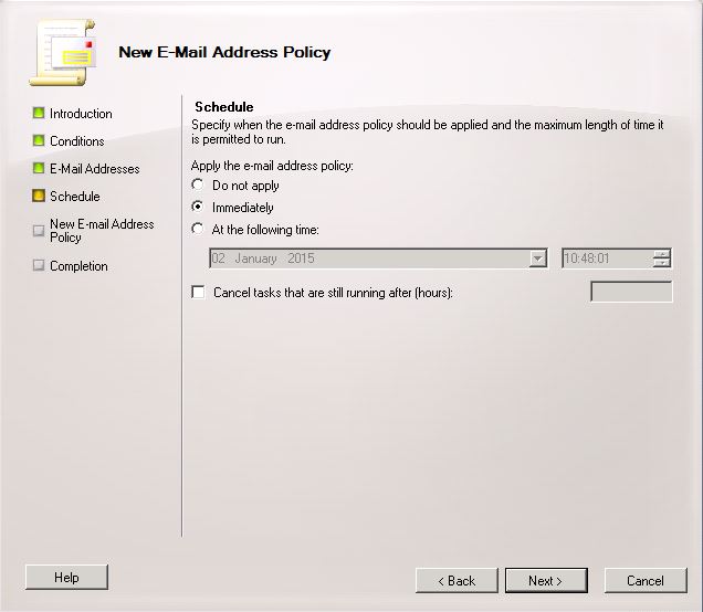
  • On the Schedule Page, leave this as Immediately

Exchange28

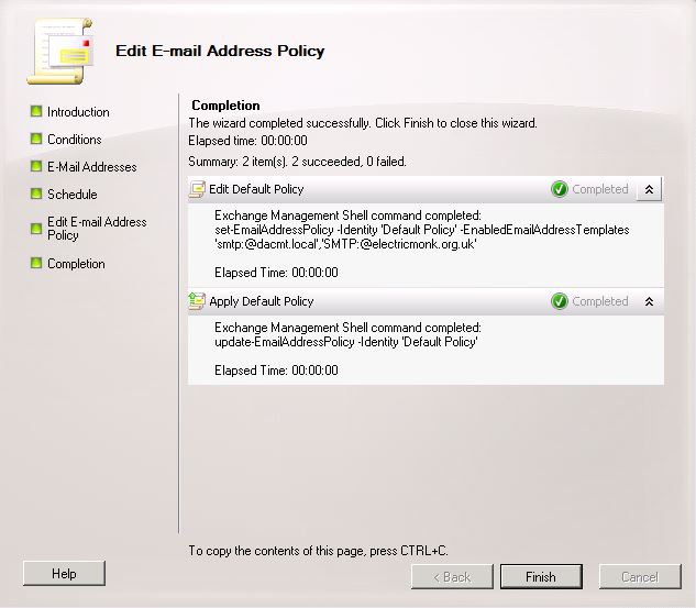
  • Finally click New and the wizard will complete

Exchange36

ActiveSync Virtual Directory

By default, when Exchange 2010 is installed, a new virtual directory is created in the default website in Internet Information Services (IIS). This virtual directory is named Microsoft-Server-ActiveSync. You can create additional Exchange ActiveSync virtual directories under Web sites other than the default Web site. All Exchange ActiveSync virtual directories you create will have the name Microsoft-Server-ActiveSync. After you have installed the Client Access server role on an Exchange Server 2010 computer, Exchange ActiveSync is enabled by default. An Exchange ActiveSync virtual directory is created on the Exchange 2010 Client Access server. You can configure a variety of options on that virtual directory.

Viewing the ActiveSync Virtual Directory Properties

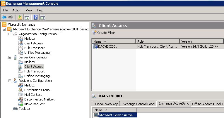
  • In the console tree, navigate to Server Configuration > Client Access
  • In the work pane, click the Exchange ActiveSync tab, and then click the Microsoft-Server-ActiveSync virtual directory.

Exchange01

  • In the action pane, under click Microsoft-Server-ActiveSync, click Properties.
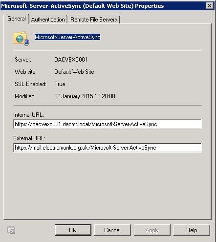
  • Use the General tab to view display-only information about the Exchange ActiveSync virtual directory and to modify the Internal and External URLs.
  • Server – This read-only field shows the name of the server the virtual directory is located on.
  • Web site   This read-only field shows the name of the Web site that holds the virtual directory. Normally, this will be the Default Website.
  • SSL Enabled   This read-only field shows the Secure Sockets Layer (SSL) status of the virtual directory. The default is True.
  • Modified   This read-only field shows the date and time that the virtual directory was last modified.
  • Internal URL   This field shows the InternalURL setting for the virtual directory. In most cases, you shouldn’t change this setting.
  • External URL   This field shows the ExternalURL setting for the virtual directory. In an Internet-facing Active Directory site, this field will be populated with the external DNS endpoint for Exchange ActiveSync, for example, http://mail.electricmonk.org.uk/Microsoft-Server-ActiveSync.

Exchange41

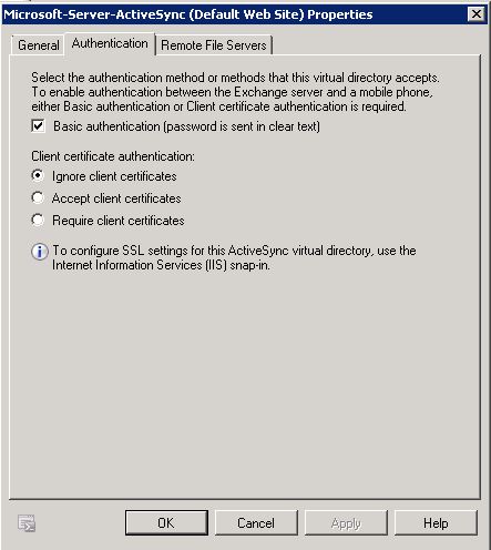
  • Use the Authentication tab to control the authentication methods for the Exchange ActiveSync virtual directory.
  • Basic authentication (password is sent in clear text) Select this check box if you want the mobile device to send the user name and password in clear text. Because passwords are sent in clear text with Basic authentication, you should configure SSL to encrypt data transferred between your mobile clients and the Exchange ActiveSync virtual directory.

Exchange03

  • Client Certificate authenticationSelect whether you want to ignore, accept, or require client certificate authentication.
  • Certificates can reside in the certificate store on a mobile device or on a smart card. A certificate authentication method uses the Extensible Authentication Protocol (EAP) and Transport Layer Security (TLS) protocols. In EAP-TLS certificate authentication, the client and the server prove their identities to each other. For example, an Exchange ActiveSync client presents its user certificate to the Client Access server, and the Client Access server presents its computer certificate to the mobile device to provide mutual authentication.

Note: Requiring client certificates will force you to configure SSL on the Web site that’s hosting the Exchange ActiveSync virtual directory.

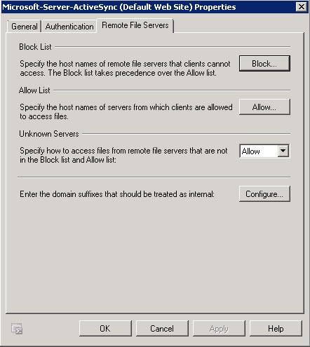
  • Exchange ActiveSync clients can access files and Web sites that are located on Windows SharePoint Services and Windows file shares. Use the Remote File Servers tab to specify allowed and blocked host names for your Exchange ActiveSync clients. This tab also allows you to configure which domains are treated as internal.
Exchange04

  • Block List – Click Block to configure a list of host names of servers to which clients are denied access.
  • The Block list takes precedence over the Allow list. To add a host name to the Block list, type the host name in the Block List dialog box, and then click Add. To remove a host name from the Block list, select the host name, and then click Delete in the Block List dialog box.
  • Allow List – Click the Allow button to configure a list of host names of servers from which clients are allowed to access files.
  • To add a host name to the Allow list, type the host name in the Allow List dialog box, and then click Add. To remove a host name from the Allow list, select the name, and then click Delete in the Allow List dialog box.
  • If a host name is specified in the Allow list and the Block list, clients will be blocked from accessing files from that host name.
  • Unknown Servers   Use this list to specify how to access files from host names that aren’t listed in either the Block list or the Allow list. The default value is Allow.
  • Enter the domain suffixes that should be treated as internal   Use this option to configure specific host names as internal host names. Click Configure to add host names to the Internal Domain Suffix List. When clients try to access files on one of these host names, Exchange ActiveSync uses the internal network to access these files instead of trying to access them over the Internet

IMAP Configuration

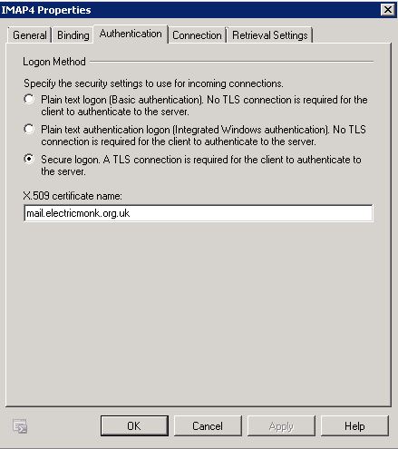
  • Go to Server Configuration
  • Go to Client Access
  • Go to POP3 and IMAP4
  • Double click on IMAP4 and go to Authentication
  • In the X.509 certificate name type in your domain

Exchange42

Enabling Anonymous Authentication

If this is not enabled, it can stop external mail programs from being able to email your Exchange server. See below when trying to send email from Gmail to my Exchange Address

Exchange52

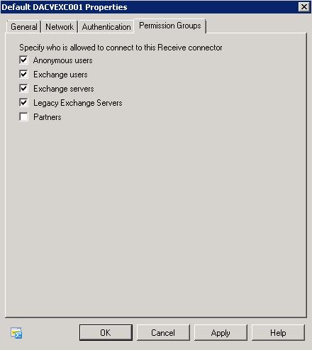
  • Open EMC
  • Go to Server configuration > Hub Transport Server
  • Click on Default Receive Connector and select Properties
  • Click on last tab “Permission Groups” and place check mark into “Anonymous users” click apply and ok.

Exchange51

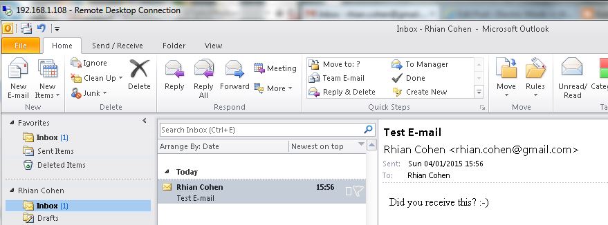
  • Now if you try resending the email it should work

Exchange53

Devices Enabled for Exchange ActiveSync

Users can take advantage of Exchange ActiveSync by selecting mobile phones that are compatible with Exchange ActiveSync. These mobile phones are available from many manufacturers. For more information, see the device documentation.

Mobile phones that are compatible with Microsoft Exchange include the following

  • Apple – The Apple iPhone, iPod Touch, and iPad all support Exchange ActiveSync.
  • Nokia – Nokia offers Mail for Exchange on their E series mobile phones. E-mail, calendar, and contact data can be synchronized over a cellular network or a wireless LAN.
  • Sony Ericsson – Sony Ericsson offers Exchange ActiveSync support on several of their newer smartphones. They also support Direct Push through a third-party program.
  • Palm – Palm offers some models of mobile phones that have the Windows Mobile operating system. These devices support Direct Push.
  • Motorola – Motorola has its own synchronization framework that enables over-the-air synchronization through Exchange ActiveSync on many of its devices.
  • Symbian – Symbian Limited licenses Exchange ActiveSync for use in the Symbian operating system. This operating system is an open standard operating system for mobile phones.
  • Android – Many mobile phones with the Android operating system support Exchange ActiveSync. However, these mobile phones may not support all available Exchange ActiveSync mailbox policies.

Setting up an iPhone 5S

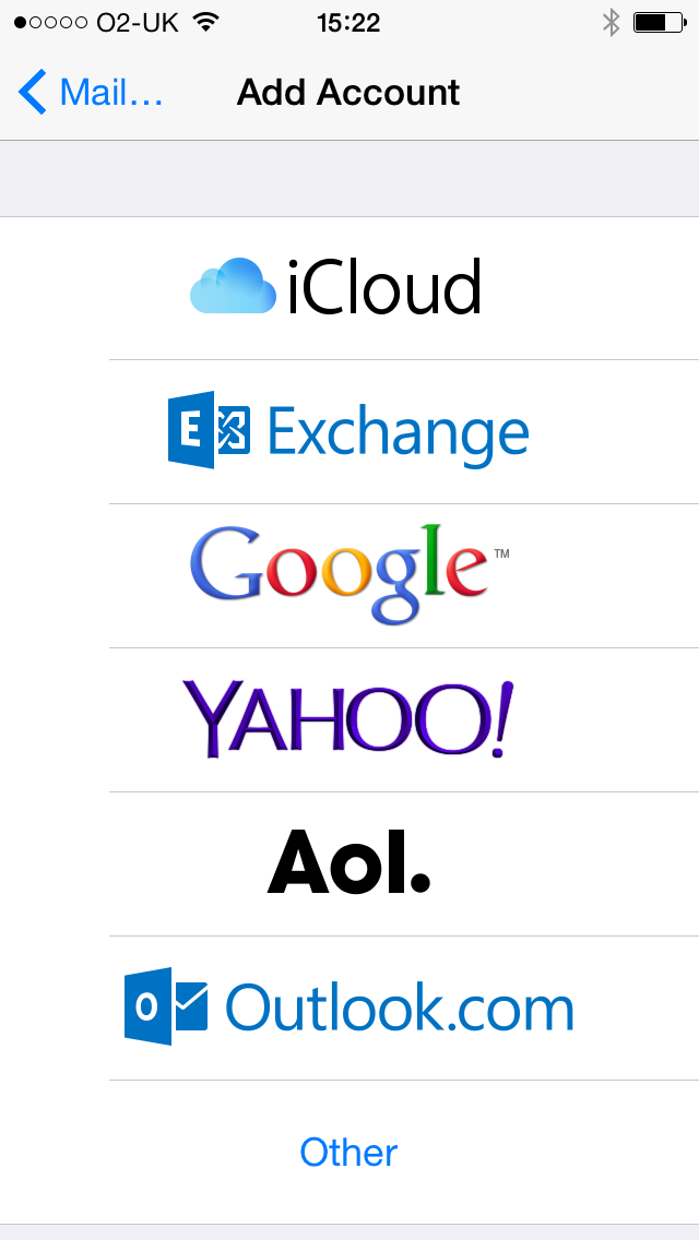
  • Go into Settings > Mail Contacts and Settings
  • Click Add Account
  • Choose Exchange

IMG_0306

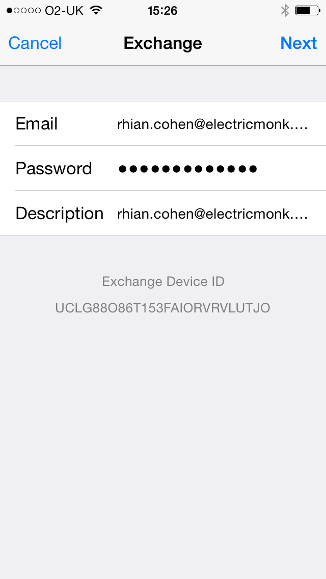
  • Put in your e-mail address and password
  • You will also see your Exchange Device ID

IMG_0308

  • Tap Next
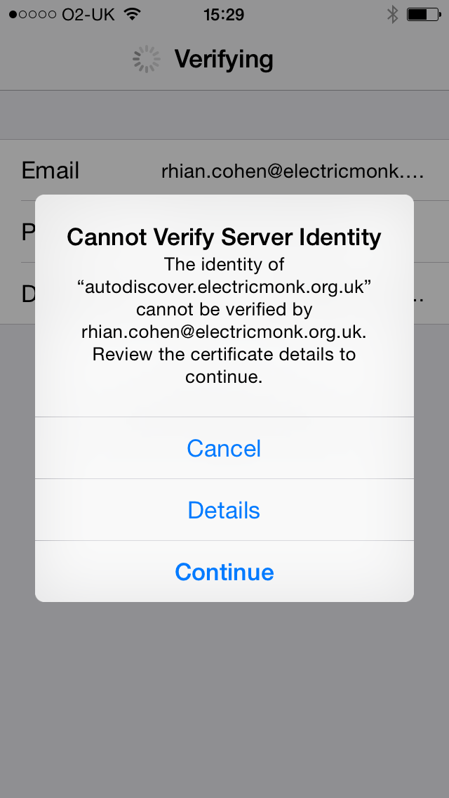
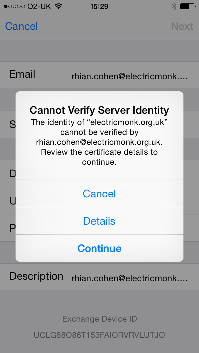
  • As I don’t have a proper certificate I get these 2 warnings. Just click Continue

IMG_0309

IMG_0310

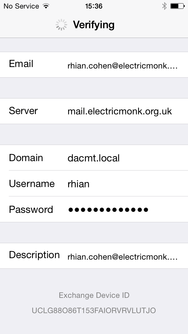
  • Next you will need to enter the relevant information for your servers and email addresses and passwords.
  • E-mail: Your e-mail address
  • Server: The external address you setup with you domain provider
  • Domain: Note: I had to put my internal local domain for this to work which is my test lab domain dacmt.local
  • Username: Active Directory Username
  • Password: Active Directory Password

IMG_0313

  • Click Done and it should say Verifying and then place a tick against all settings
  • Now you need to test sending an email to your email account

If all the settings verify but email is not coming through

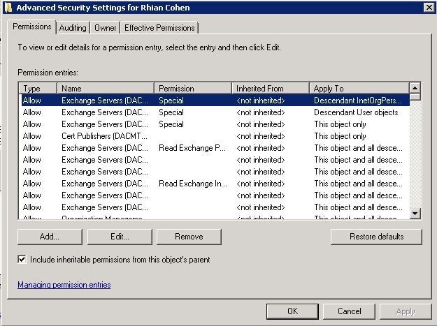
This may be the cause of a simple mis-configuration in the Microsoft Active Directory services for that user.

  • Open the Active Directory Users and Computers
  • Select the View menu from the top and click on “Advanced Features”.
  • Open the properties on the user having the issue and select the “Security” tab. Under this tab will be windows with user accounts listed and a “Advanced button” at the bottom. Select this button and find the check box “Include Inheritable permissions from this object’s parent” . If this is the problem you will find the box “unchecked”. Just check the box and try again. You should see mail start to come in.

Exchange54

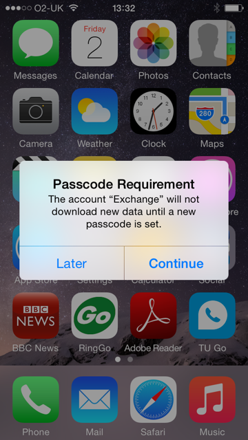
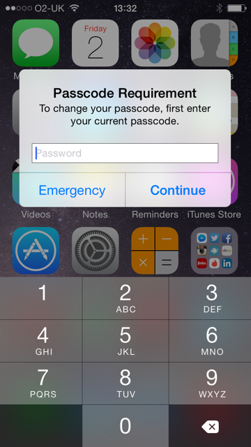
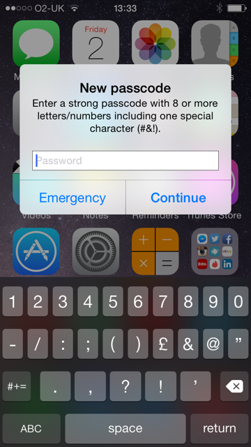
If you have set an Exchange Active Sync Policy which requires a password

Then when the account is setup, after a few minutes it should come up with the following prompts

IMG_0034

IMG_0035

IMG_0036

Using Remote Wipe

Mobile phones can store sensitive data that belongs to your organization and provide access to many of your organization’s resources. If a mobile phone is lost or stolen, that data can be compromised. Remote device wipe is a feature that enables the Exchange server to set a mobile phone to delete all data the next time that the mobile phone connects to the Exchange server. A remote device wipe effectively removes all synchronized information and personal settings from a mobile phone. This can be useful when a mobile phone is lost, stolen, or otherwise compromised. After a remote device wipe has occurred, data recovery is very difficult. However, no data removal process leaves a mobile phone or other mobile device as free from residual data as it is when it’s new. Recovery of data from a mobile phone or other mobile device may still be possible using sophisticated tools.

Microsoft Exchange Server 2010 lets you send a command to a mobile phone to perform a remote device wipe of that phone. This process removes all the information that’s stored on the phone. This includes Exchange information. This process then completes a full reset of the device. You can use the EMC or the Exchange Management Shell to perform a remote wipe on a mobile phone. You can use this procedure to clear data from a stolen phone or to clear data from a phone before you assign it to another user

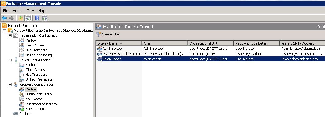
  • In the console tree, navigate to Recipient Configuration > Mailbox.
  • Select the user from the Mailbox window.

Exchange12

  • In the action pane, click Manage mobile device, or right-click the user’s mailbox, and then click Manage mobile device.
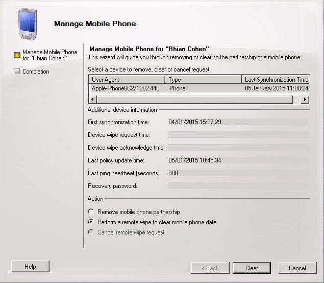
  • Select the mobile phone you want to clear all data from.
  • In the Actions section, click Perform a remote wipe to clear mobile phone data

Exchange55

  • Click Clear.
  • Note: Performing either of these actions will wipe the iPhone!
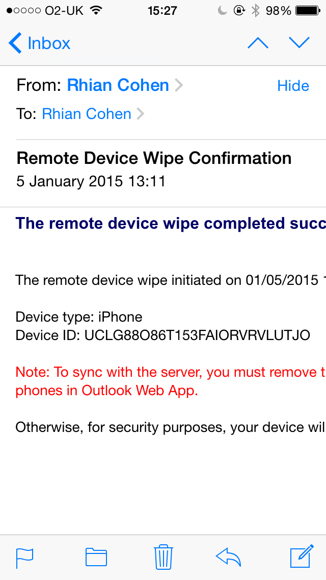
  • It will also send an email message to you saying that the device has been wiped

IMG_0132

Recovering a Device Password

Note: This feature does not appear to be available for iPhones unfortunately which is a shame as the only option is to wipe the phone to get round a forgotten password

http://en.wikipedia.org/wiki/Comparison_of_Exchange_ActiveSync_clients

You can use

  • The EMC
  • The Shell
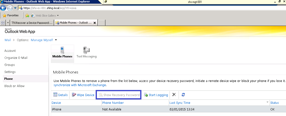
  • Microsoft Office Outlook Web App to recover a device password.

You can require a device password through Microsoft Exchange ActiveSync policies. A user can configure a device password even if your Exchange ActiveSync policies don’t require one. If users forget their password, you can obtain a recovery password using the EMC or the Shell. The recovery password unlocks the device and lets the user create a new password. Users can also recover their device passwords by using Outlook Web App.

The EMC

You need to be assigned permissions before you can perform this procedure.

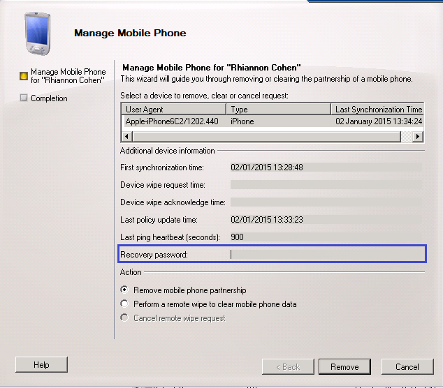
  • In the console tree, navigate to Recipient Configuration > Mailbox.
  • In the details pane, select a user, and then select Manage Mobile Device from the action pane. The device recovery password is displayed in the Manage Mobile Device dialog box

exchangeactivesync1

The Shell

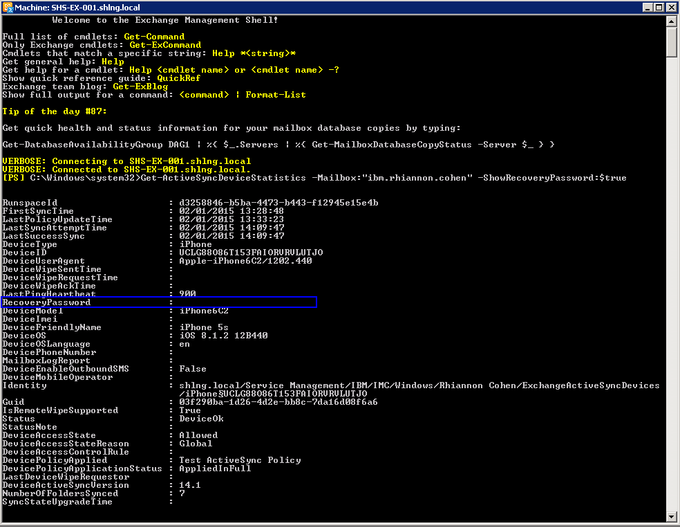
  • Open Exchange Management Shell
  • Type Get-ActiveSyncDeviceStatistics -Mailbox:”rhian.cohen” -ShowRecoveryPassword:$true

exchangeactivesync3

Outlook Web Access

  • Log into Outlook Web Access
  • Click on Options

exchangeactivesync2 Useful links

http://technet.microsoft.com/en-us/library/bb124558(v=exchg.141).aspx http://technet.microsoft.com/en-us/library/aa998357.aspx#WindowsPhone7 https://www.apple.com/kr/ipad/business/docs/iOS_6_EAS_Sep12.pdf

Youtube Tutorials (Thanks to Hotfoot Training

Part 1 https://www.youtube.com/watch?v=dDg4oY1oUzQ

Part 2 https://www.youtube.com/watch?v=2tyhnOptqZ0

Part 3 https://www.youtube.com/watch?v=glASOiu8yMY

Installing McAfee Change Control 6.1.3 and monitoring a CIFS Share

McAfee ChangeControl

What is McAfee Change and Application Control?

Changes in server environments are constantly taking place in many organizations today—and going undetected. It’s a situation that is dangerous, both in terms of security and compliance. McAfee® Change Control delivers continuous, enterprise-wide detection of authorized changes as they occur. It blocks unauthorized changes to critical system files, directories, and configurations while streamlining the implementation of new policies and compliance measures.

Key Advantages

  • Gain continuous visibility and real-time management of changes to critical system, configuration, or content files.
  • Prevent tampering with critical files and registry keys by unauthorized parties.
  • Fulfill the PCI DSS regulation requirement for file integrity monitoring system.
  • Easy to get started with out-of the- box FIM rules.
  • QSA-friendly reports for easy PCI reporting.
  • One-click exclusion feature to avoid tracking irrelevant information.
  • Tight policy enforcement via proactively blocking of out-ofprocess and unwanted changes before they occur.
  • Integrates with McAfee® ePolicy Orchestrator® (McAfee ePO™) console for centralized IT management.

The Task

Install Change Control or Application Control in the McAfee® ePolicy Orchestrator® (McAfee ePO™) environment. For use with ePolicy Orchestrator 4.6.0 – 5.1.0 Software

Pre-Requisites

  • Verify that the McAfee ePO server and database are installed and configured. McAfee ePO is a management tool that installs software and deploys policies on the managed endpoints. It also allows you to monitor client activity, create reports, and store and distribute content and software updates. For instructions, see the ePolicy Orchestrator Installation Guide and ePolicy Orchestrator Product Guide.
  • Make sure that the McAfee Agent is installed on each endpoint on which you want to install Change Control or Application Control. McAfee Agent acts as the intermediary between the Solidcore client and McAfee ePO server. It sends data to the client from the McAfee ePO server and vice versa.
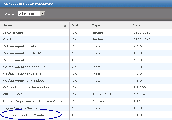
  • Download the Solidcore extension package from the McAfee Downloads site. The Solidcore extension file is typically named Solidcore_epo_extn_<ver>.<build>.zip.
  • Download the Solidcore client package from the McAfee Downloads site. Here are the available Solidcore client packages.

Change01

  • Make sure that the endpoints on which you need to install the Solidcore client are supported. See KB76459 (for Change Control) and KB73341 (for Application Control)
  • Review the KnowledgeBase article (see KB76544) to determine if a precompiled binary is available for your Linux target kernel.
  • If a precompiled binary is available for your target kernel, you need not meet any prerequisites and can directly proceed with installation (see Install the Solidcore client on the endpoints).
  • If a precompiled binary is unavailable for your target kernel, see Linux installation workflow for information on prerequisites and installation.
  • Determine the database sizing requirements for your setup (see KB72753).
  • Review the minimum system requirements for Change Control and Application Control (see KB76579).
  • Review the release notes to acquaint yourself with the known issues and identify dependencies you need to consider.

Installation Steps

  • Install the Solidcore extension. The Solidcore extension integrates with the McAfee ePO console and provides Change Control and Application Control features. The Solidcore extension installs on versions 4.6, 5.0, and 5.1 of the McAfee ePO server.
  • Log into your EPO Server
  • Make sure that the extension file is stored at an accessible location.
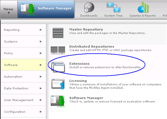
  • On the McAfee ePO console, select Menu | Software | Extensions to open the Extensions page.

Change02

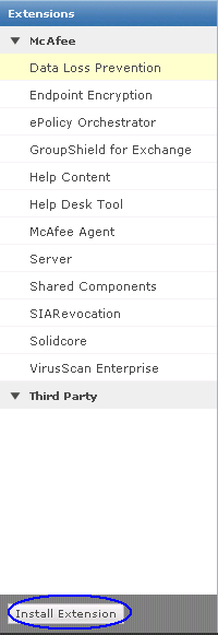
  • Click Install Extension.

Change03

  • Browse and select the Solidcore_epo_extn_<ver>.<build>.zip file, then click OK
  • Verify the information on the Install Extension page, then click OK
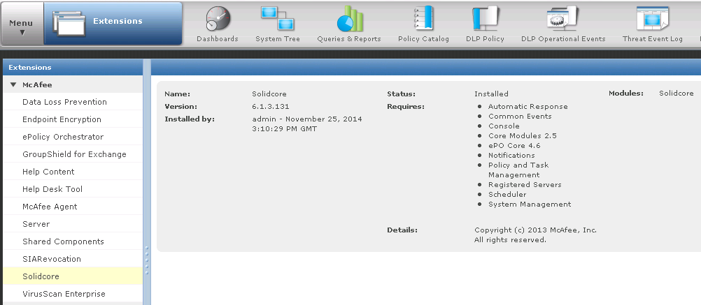
  • Verify that the Solidcore product name appears in the Extensions list.

Change04

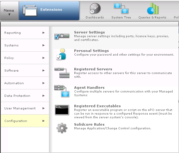
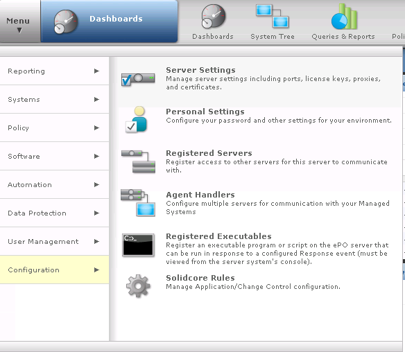
  • On the McAfee ePO console, select Menu | Configuration | Server Settings to open the Setting Categories page.

Change05

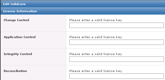
  • Select Solidcore, then click Edit to open the Edit Solidcore page.
  • Enter the license keys, then click Save. Evaulation Licenses last for 30 days

Change06

  • Now we need to install the Solidcore client
  • The Solidcore client provides change monitoring, change prevention, and whitelisting features on the endpoints on which it is installed. You can install and deploy the Solidcore client on Windows, Linux, and AIX platforms. For all supported platforms, the Solidcore client works well on both physical and virtual machines (VM)
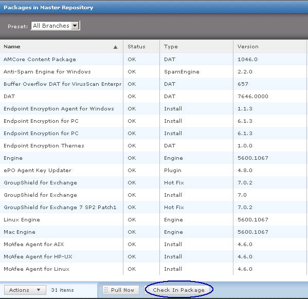
  • On the McAfee ePO console, select Menu | Software | Master Repository.
  • From the Packages in the Master Repository page, select Actions | Check In Package.

Change07

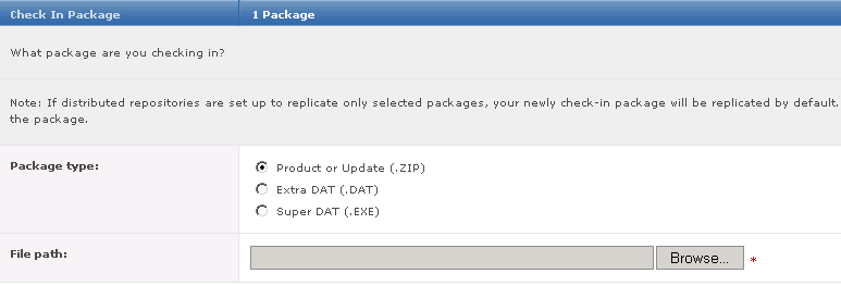
  • Set the package type to Product or Update (.ZIP).

Change08

  • Browse and select the package zip file and click Next to open the Package Options page.
  • Confirm the information.
    • Package Info: Verify the package details.
    • Branch: Select the desired branch. Set to Current for new products.
    • Options: Optionally, select Move the existing package to the Previous branch to move an existing package to
    the previous branch.
    • Package signing: Indicates if the package is signed by McAfee or is a third-party package.
  • Click Save to add the package. The new package appears in Packages in Master Repository list.

Change10

  • Now we need to set up a task to install the Client on a test endpoint
  • On the McAfee ePO console, select Menu | Systems | System Tree.
  • Perform one of these actions:
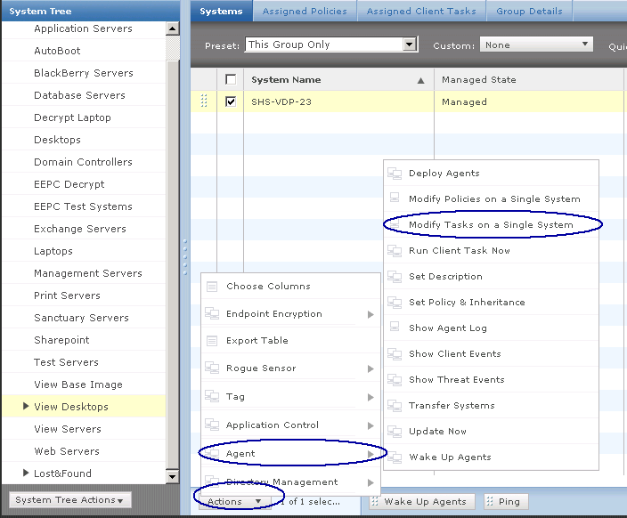
    • To apply the client task to a group, select a group in the System Tree and switch to the Assigned Client Tasks tab.
    • To apply the client task to an endpoint, select the endpoint on the Systems page and click Actions | Agent | Modify Tasks on a Single System.
  • I am just testing this on my VDI VM at the moment so I choose the first option as per below screenprint

Change11

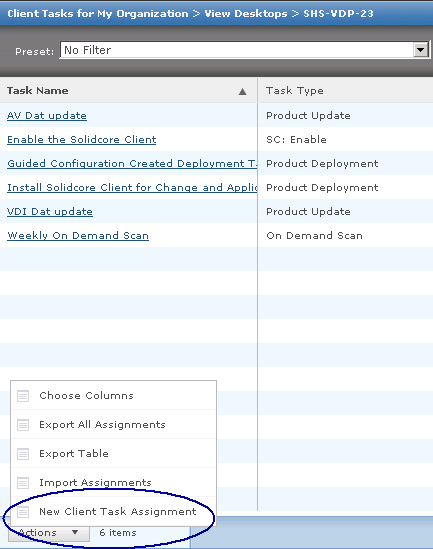
  • Click Actions | New Client Task Assignment to open the Client Task Assignment Builder page.

Change12

  • Select the McAfee Agent product and Product Deployment task type, then click Create New Task.

Change13

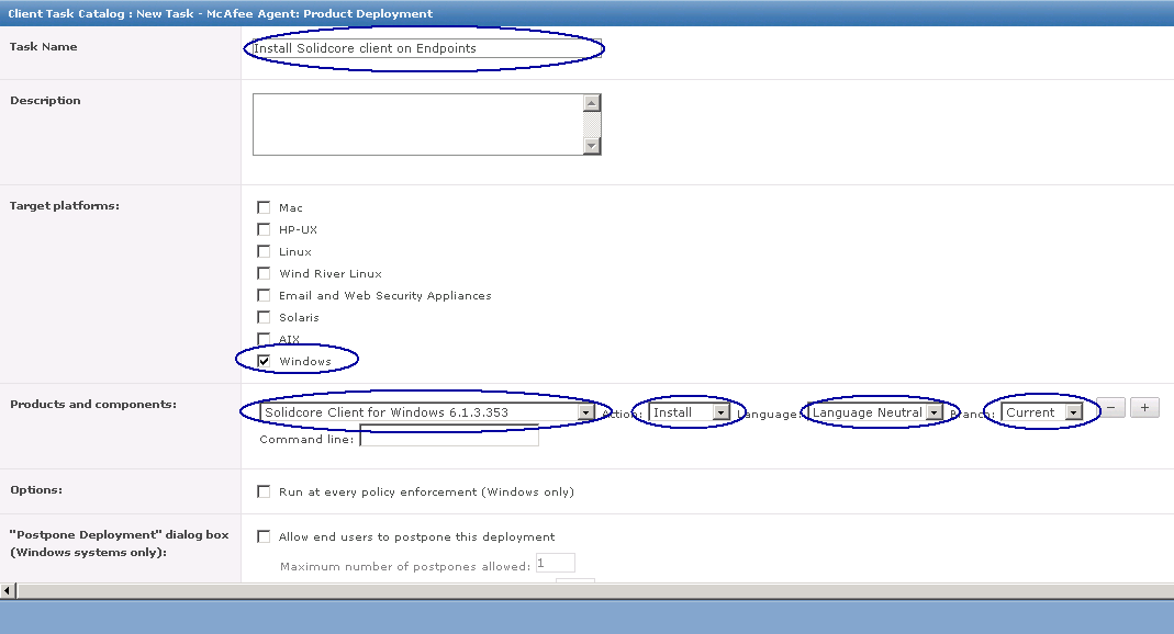
  • Specify the task name and add any descriptive information.
  • Select the target platform. For example, when installing the Solidcore client package on the Windows operating system, select Windows as the target platform.
  • Specify the component and action.
    a Select the appropriate package from the Products and components list.
    b Select the Install action.
    c Select the language of the package.
    d Specify the branch from which to add the package.
  • Click Save, then click Next to open the Schedule page.

Change14

  • Specify scheduling details, then click Next.
  • Review and verify the task details, then click Save.
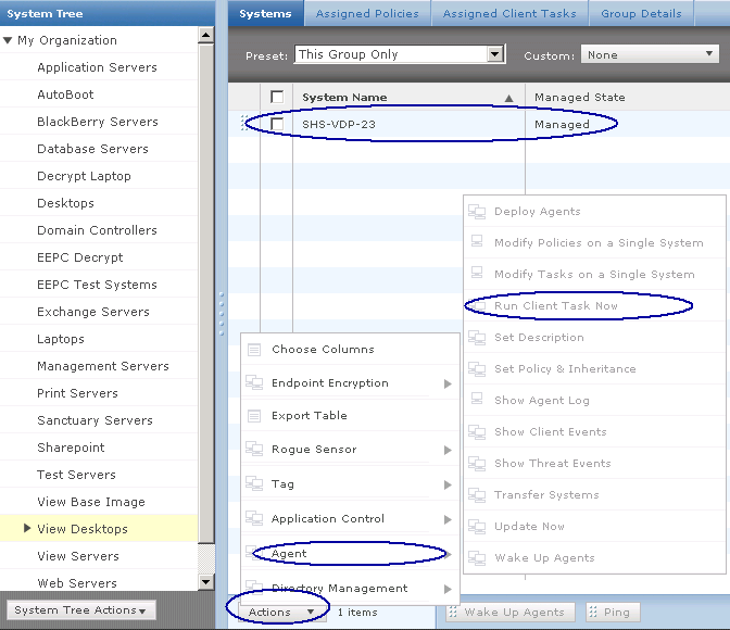
  • Next select your test VM and click Action > Agent > Run Client Task Now

Change15

  • Choose the following as per the screenprint below

Change16

  • Click Run Task now and wait until this task completes
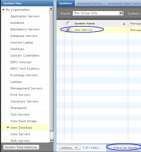
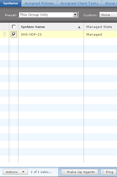
  • Note you may need to wake up the agents. Click on your test VM and click Wake up Agents as below

Change17

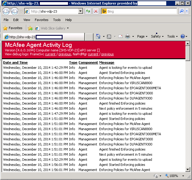
  • Now we can check the verify the agent installation by checking the log
  • Select Actions | Agent | Show Agent Log to view the agent log for the endpoint.

Change18

  • We now need to place the Solidcore client in Enabled mode to activate the software.
  • On the McAfee ePO console, select Menu | Systems | System Tree.
  • Perform one of these actions:
    • To apply the client task to a group, select a group in the System Tree and switch to the Assigned Client Tasks tab.
    • To apply the client task to an endpoint, select the endpoint on the Systems page and click Actions | Agent | Modify Tasks on a Single System.
  • Click Actions | New Client Task Assignment to open the Client Task Assignment Builder page.
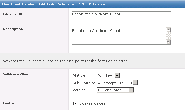
  • Select the Solidcore 6.1.3 product and SC: Enable task type, then click Create New Task.
  • On the Client Task Catalog page, specify the task name and add any descriptive information.
    6 Select these fields.
    a Select the platform.
    b Select the subplatform (only for the Windows and Unix platforms).
    c Select the version (only for the All except NT/2000 subplatform).
    d Indicate whether to enable Change Control, Application Control, or both
  • Click OK and if you go back into it, it should look like the below

Change19

  • No reboot should be necessary at this point
  • Next select your test VM and click Action > Agent > Run Client Task Now and select the following to run the Enable Task

Change20

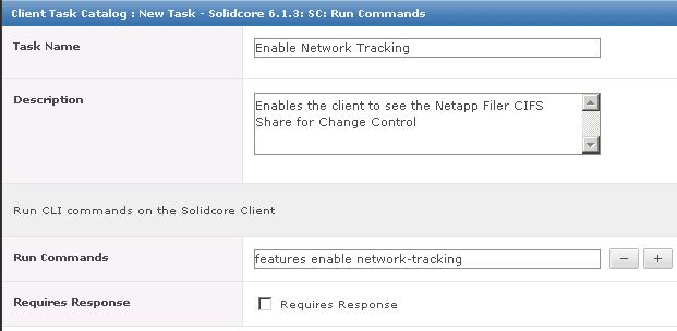
  • We now need to create a task that enables network tracking
  • Select the endpoint on the Systems page and click Actions | Agent | Modify Tasks on a Single System.
  • Click Actions > New Client Task Assignment
  • Under Product Select Solidcore 6.1.3
  • Under Task Type Select SC: Run Commands
  • Under Task Name select to Create new Task
  • In Run Commands type features enable network-tracking
  • Click Save

Change21

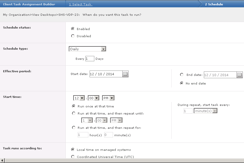
  • Set the schedule as per below screen-print

Change22

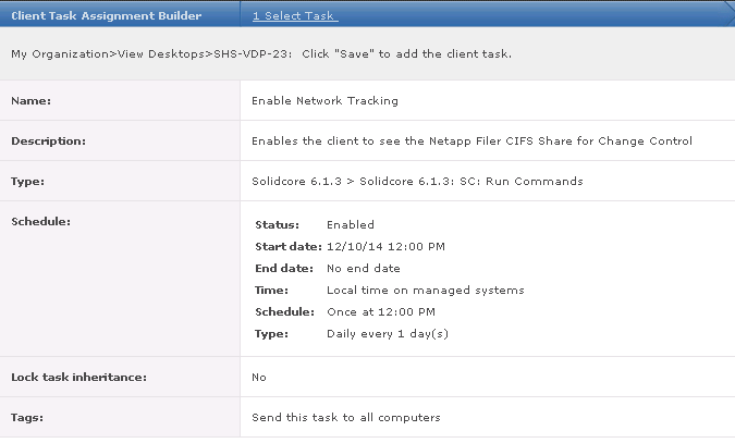
  • Click Next and you will see a summary then click Save

Change23

  • Next select your test VM and click Action > Agent > Run Client Task Now and select the following to run the Enable Task

Change24

  • Next we need to create Rule Groups
  • A rule group is a collection of rules. Although you can directly add rules to any McAfee ePO-based policy, the rules defined within a policy are specific to that policy. In contrast, a rule group is an independent unit that collates a set of similar or related rules. After you define a rule group, you can reuse the rules within the rule group by associating the rule group with different policies. Also, if you need to modify a rule, simply update the rule in the rule group and the change cascades across all associated policies automatically.
  • On the McAfee EPO Console, select Menu > Configuration > Solidcore Rules

Change25

  • Keep Integrity Rules selected and because we have Windows 7 client machines which have a Netapp CIFS Share mapped on them, I am going to duplicate the Windows 7 (64 bit) Base Filters Rule Group. If you have Windows 2008 file servers, you would duplicate a rule group for these.
  • Select the Windows 7 (64 bit) Base Filters Rule Group and click Duplicate

Change26

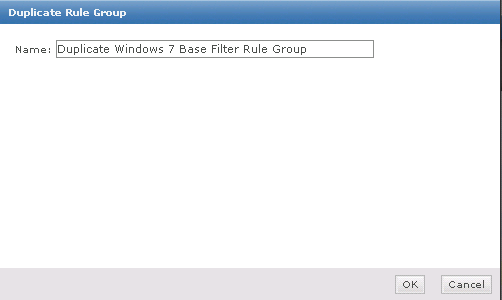
  • Put a name in your Rule Group

Change27

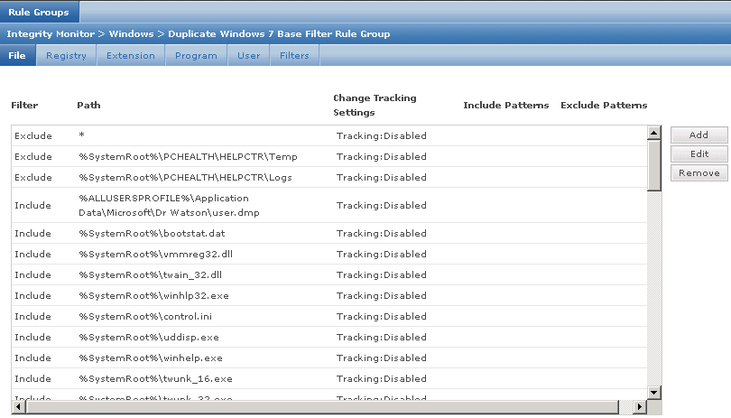
  • Click Edit on your duplicate rule group

Change28

  • Have a look through the top options – File, Registry, Extension, Program, User, Filters
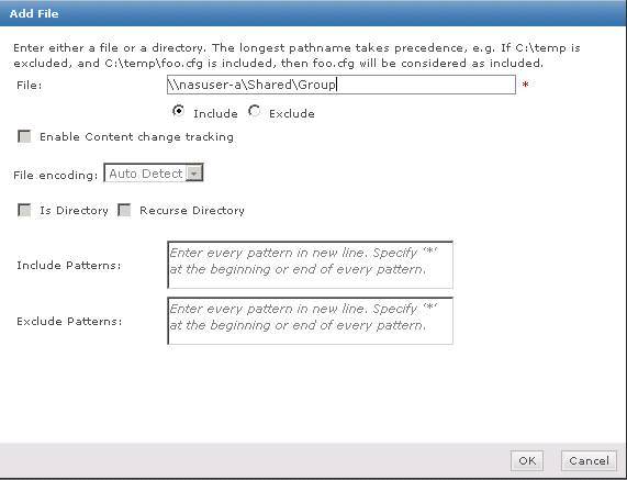
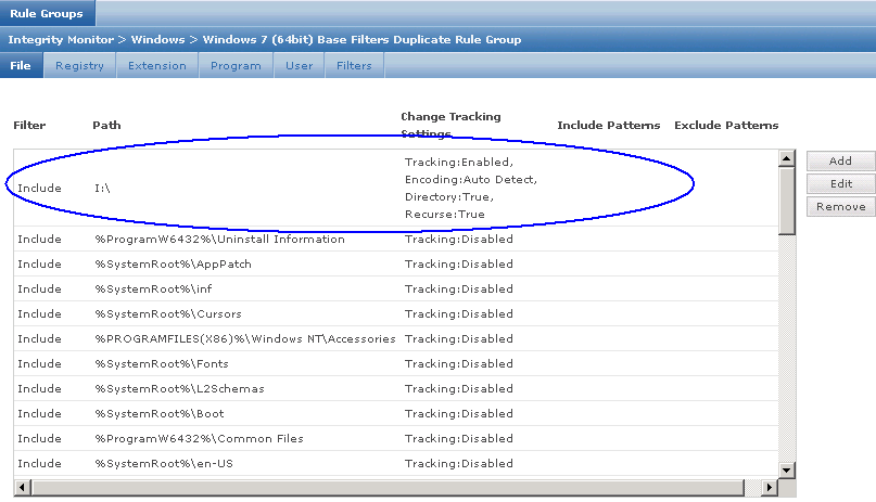
  • What we are going to do on the File column is click Add and add our Netapp Filer share which is \\nasuser-a\shared\group
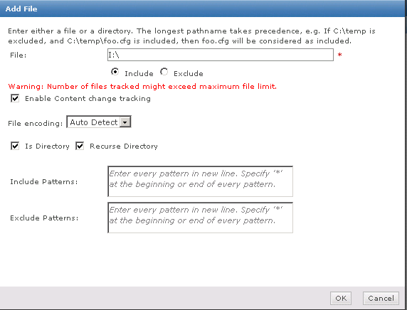
  • This share is also mapped to our I Drive so I will add this in as well as I:\

Change29

Change31

  • Click Save Rule Group
  • It should now look like the below

Change32

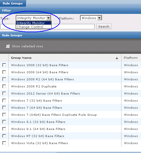
  • Next within Rule Groups, change from Integrity Control to Change Control

Change33

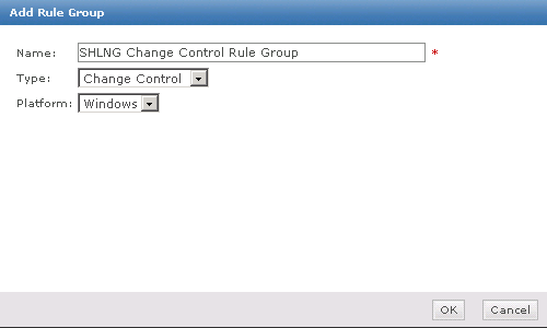
  • Click Add Rule Group
  • Put a name in and keep Change Control selected and Windows

Change34

  • Click OK and click Save Rule Group
  • Next we need to set up an Integrity Policy and a Change Control Policy
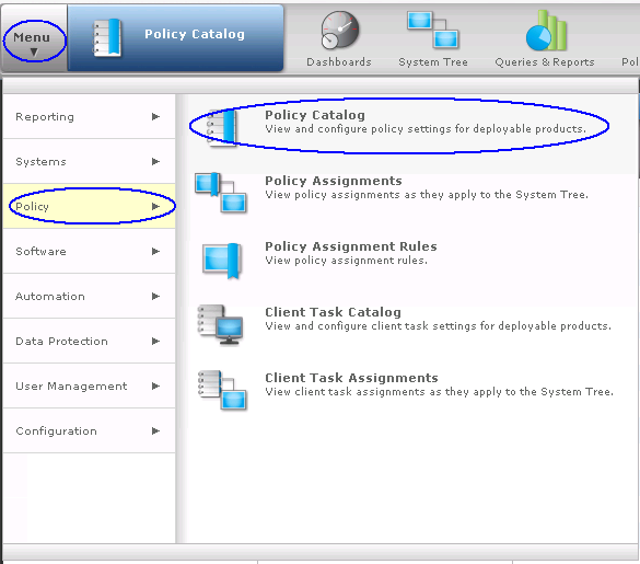
  • Go to Menu > Policy > Policy Catalog

Change36

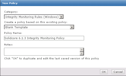
  • Switch to Solidcore 6.1.3 Integrity Monitor and Integrity Monitoring Rules (Windows)

Change37

  • Click Actions > New Policy and give it a name. You can also duplicate the policy

Change38

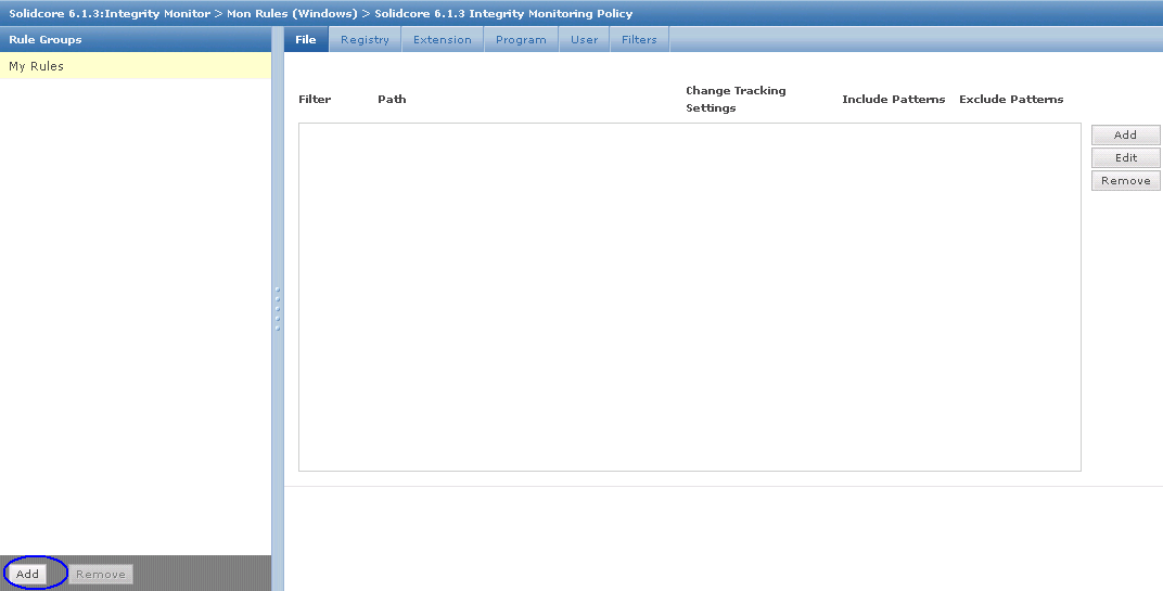
  • The Rule Group box will appear. Click Add Rule Group and select your Rule Group

Change39

  • Click Save
  • You should now see your Monitoring Policy as per below screenprint

Change41

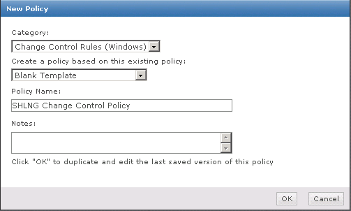
  • Next in the Policy Catalog change to Solidcore 6.1.3 Change Control and Change Control Rules (Windows)

Change42

  • Click Actions > New Policy > Decide whether to create a policy from a blank template and put in a name

Change43

  • In the Rules you can add your existing Rule Group or add some test rules under My Rules

Change44

  • Click Save
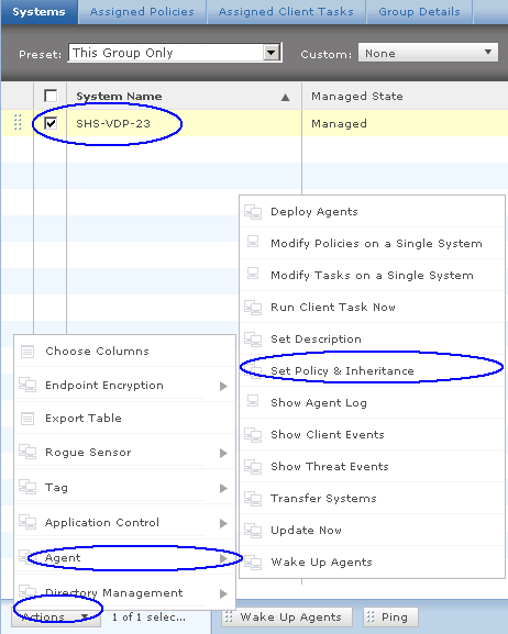
  • Go back to System tree and select your test VDI and click on Action > Agent > Set Policy inheritance

Change45

  • Choose your Integrity Monitor Policy and Break Inheritance and click Save

Change46

  • Next we need to do the same but for the Change Control Policy
  • Click Action > Agent > Set Policy and Inheritance
  • Choose your Change Control Settings

Change47

  • Go back to System Tree and click on your VDI and select Wake up Agent

Change48

  • Now we need to log on to our VDI and check some bits and pieces and test accessing a folder and file and see what gets logged within the EPO Console in the Solidcore events
  • Once you have edited a file, come back to the EPO and go to Menu > Reporting > Solidcore Events

Adding shared RDM’s to multiple VMs in VMware vSphere 5.5

RDM2

The Task

For this task we had 6 x RHEL6 VMs which someone had asked us to attach the same RDM disk to in a non cluster aware scenario. E.g No SQL/Exchange clustering, just the simple sharing of a LUN between the VMs.

About RDM Mapping

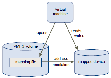
An RDM is a mapping file in a separate VMFS volume that acts as a proxy for a raw physical storage device.
The RDM allows a virtual machine to directly access and use the storage device. The RDM contains metadata for managing and redirecting disk access to the physical device.
The file gives you some of the advantages of direct access to a physical device while keeping some advantages of a virtual disk in VMFS. As a result, it merges VMFS manageability with raw device access. RDMs can be described in terms such as mapping a raw device into a datastore, mapping a system LUN, or mapping a disk file to a physical disk volume. All these terms refer to RDMs.

RDM

Although VMware recommends that you use VMFS datastores for most virtual disk storage, on certain occasions, you might need to use raw LUNs or logical disks located in a SAN.

When you give your virtual machine direct access to a raw SAN LUN, you create an RDM disk that resides on a VMFS datastore and points to the LUN. You can create the RDM as an initial disk for a new virtual machine or add it to an existing virtual machine. When creating the RDM, you specify the LUN to be mapped and the datastore on which to put the RDM.
Although the RDM disk file has the same.vmdk extension as a regular virtual disk file, the RDM contains only mapping information. The actual virtual disk data is stored directly on the LUN.

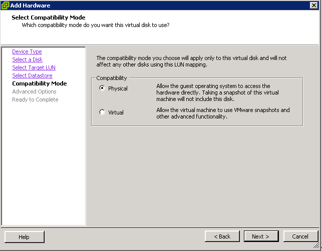
Compatibility Modes

Two compatibility modes are available for RDMs:

  • Virtual compatibility mode allows an RDM to act exactly like a virtual disk file, including the use of snapshots.
  • Physical compatibility mode allows direct access of the SCSI device for those applications that need lower level control.

Instructions

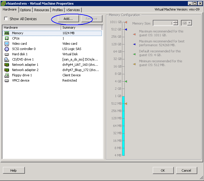
  • Log into vCenter and go to the first VM and click Edit Settings. Note the VM will need to be powered off for you to configure some settings further on in the configuration.

rdm1

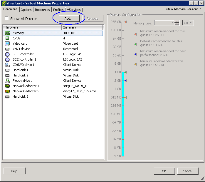
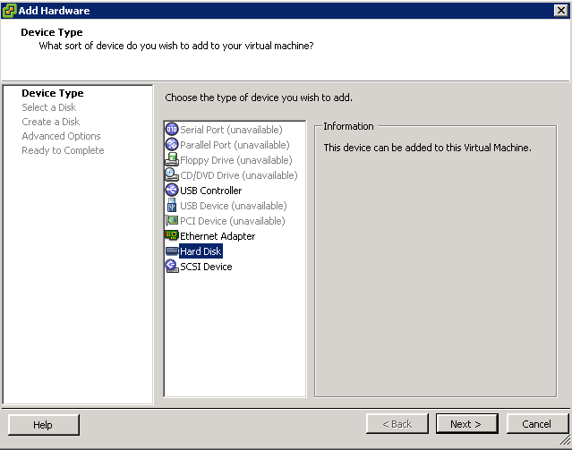
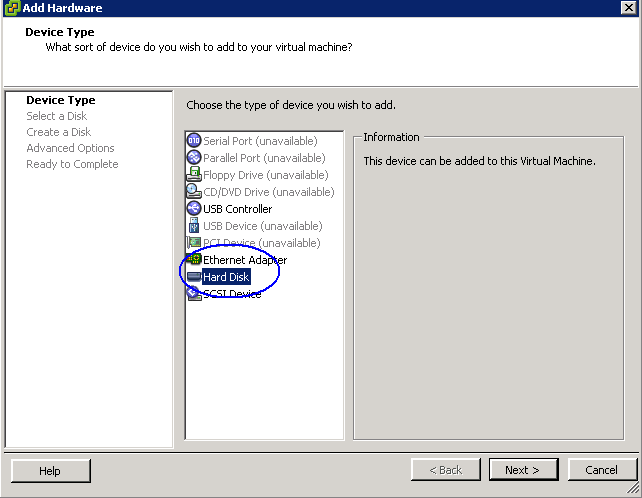
  • Click Add and choose Hard Disk

rdm2

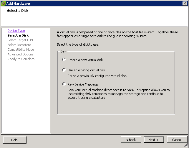
  • Choose Raw Disk Mapping

rdm3

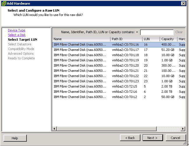
  • Select the Raw Disk you want to use

rdm4

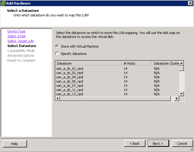
  • Select whether to store it with the VM or on a separate datastore

rdm5

  • Choose a Compatibility Mode – Physical or Virtual. We need to choose Physical

rdm6

  • Choose a SCSI Device Mode. This will also need to be the same on the second machine you are going to add the same RDM to.

rdm7

  • Click Finish
  • Next go the second VM and click Edit Settings and click Add

rdm8

  • Click

rdm9

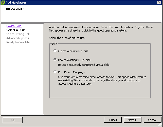
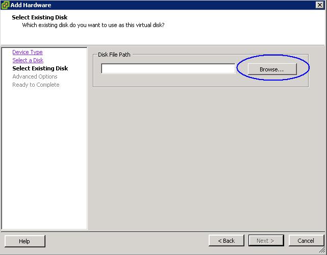
  • Click Choose an Existing Disk

rdm10

  • You now need to browse to the Datastore that the first VM is one and find the RDM VMDK file and select this

rdm11

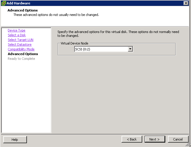
  • In Advanced Options, select the same SCSI ID that the first VM containing the RDM is on
  • Click Finish and the Edit Settings box will come up again
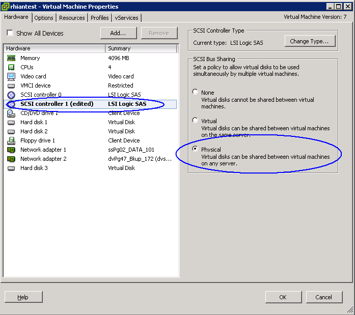
  • You need to change the SCSI Bus Sharing on the Controller to Physical to Allow Sharing

rdm12

  • Click OK
  • You should now have a shared RDM between 2 VMs
  • Power on the VMs

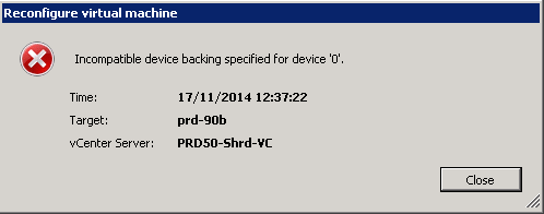
Problems: Incompatible Device backing for device 0

We actually encountered an issue where we tried to accept the settings on the second VM and got the following error message

lun

We resolved it by having a member of our storage team recreating the LUNS we needed to add on the SAN. When sharing MSCS RDM LUNs between nodes, ensure that the LUNs are uniformly presented across all ESXi/ESX hosts. Specifically, the LUN ID for each LUN must be the same for all hosts.

In our case with VMware and Windows clusters we use the IBM v7000 GUI to map the LUNs which is easier – It assigns the first available SCSI ID. No issues with these Operating Systems.
But with Red Hat it didn’t work, because it uses SCSI ID together with WWNs. So we had to use v7000 CLI to map the LUNs with one and the same SCSI ID to every host

 If the LUN IDs are not the same across hosts, contact your storage admin, team or storage vendor to change the LUN ID appropriately. It is a better practice to assign the LUN to a new, previously unused ID and present the LUN under the new ID to the cluster.

Putting desktop shortcuts on via Group Policy

Shortcut

Putting desktop shortcuts on via Group Policy

Today’s blog has come up as someone asked me about putting a folder shortcut on our Terminal Server for a subset of users who log in. It turns out you can do a whole lot more with different types of shortcuts and even customise them with different icons to make them stand out.

The Task

Certain users will log into the Terminal Server and will see an icon on the desktop which is basically a shortcut to a shared folder held elsewhere on another server. This a Windows Server 2008 R2 Server with Service Pack1. The Domain Controller is also a Windows Server 2008 R2 Server.

Instructions

  • Share the folder you want to create a shortcut to on the other server to the terminal server and assign the necessary Share and Security permissions
  • Open your Group Policy Management Console either on the DC or via an MMC
  • Right click on the Terminal Server OU and select Create a GPO in this domain and link it here
  • Put a name in for the Policy
  • Click on the new policy and go to the Scope tab
  • In the scope, click Add and select the users or group you want the policy to apply to
  • Right click on new policy and select Edit
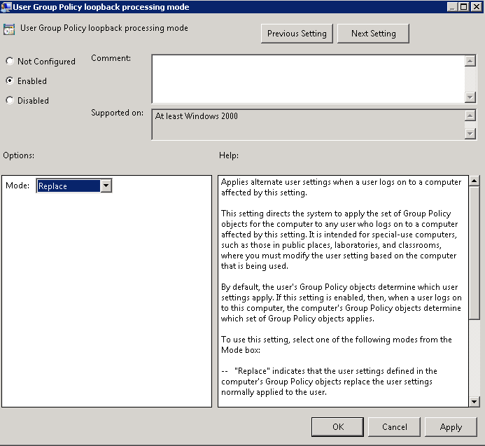
  • Navigate to Computer Configuration>Administrative Templates>System>Group Policy and Enable Group Policy loopback processing mode to Enabled and Replace

gpo1

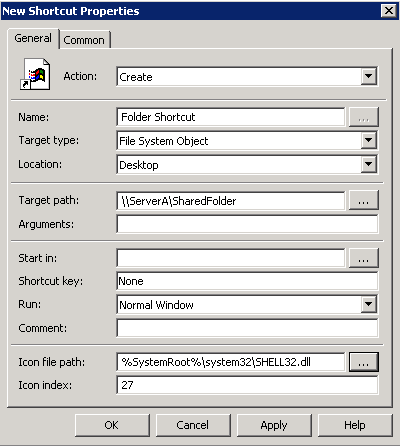
  • Go to User Configuration > Preferences > Windows Settings > Shortcuts. Right click on Shortcuts and select New Shortcut
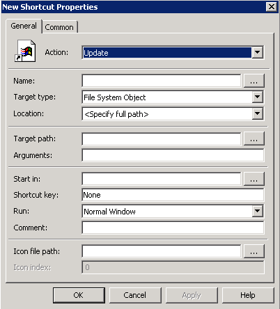
  • You will see the following default screen

gpo2

  • In Action, Select Create
  • In Name, Put in a relevant name for your shortcut
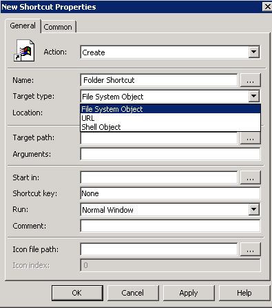
  • Now you have 3 options

gpo3

  • If you are using a Windows path (such as a file, folder, drive, share, or computer), click File System Object.
  • If you are using a URL (such as a Web page, Web site, or FTP site), click URL.
  • If you are using an object within the Windows shell (such as a printer, desktop or control panel item, file, folder, share, computer, or network resource), click Shell Object
  • For our option today, I will be using File System Object
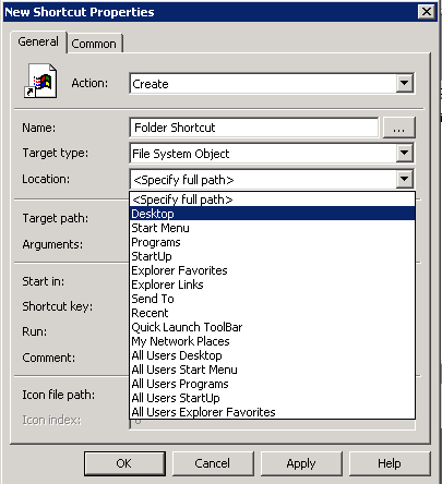
  • In Location, you will see the below options. Choose Desktop

gpo4

  • In Target Path put in the Server and Sharename. E.g \\ServerA\SharedFolder
  • If you want to have a look at the other options, please click Help at the bottom of the Properties box. For now leave everything as it is except the bottom option where you can change the Icon File Path
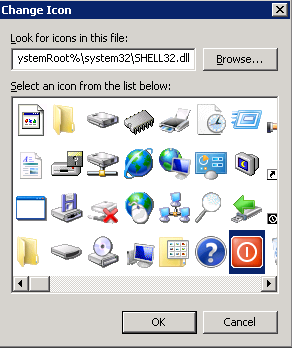
  • Click the Radio button and a collection of icons will appear
  • You cannot put your own icons in the location %SystemRoot%\system32\SHELL32.dll

gpo5

  • Choose an icon
  • Now you should have a Properties box which looks like the following

gpo6

  • Click OK
  • On the Domain Controller, click on Start > Run and type gpupdate /force
  • On the Terminal Server, click on Start > Run and type gpupdate /force
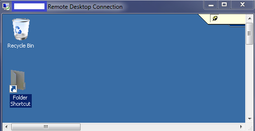
  • Test logging in as a user who the policy should apply to and check the desktop shortcut appears with the icon

gpo7


Installing McAfee Device Control

1414427055_MB__USB

What is McAfee Device Control?

McAfee Host Data Loss Prevention software is one of the core security functions which protects enterprises from the risk associated with unauthorized transfer of data from within or outside the organization. Data loss is defined as confidential or private information leaving the enterprise as a result of unauthorized communication through channels such as applications, physical devices, or network protocols.

Memory sticks are the smallest, easiest, cheapest, and least-traceable method of downloading large amounts of data, which is why they are often considered the “weapon of choice” for unauthorized data transfer. McAfee Device Control allows monitoring and controlling external device behaviour based on the device attributes rather than the content being copied. Using McAfee Device Control, devices attached to enterprise computers, such as smart phones, removable storage devices, Bluetooth devices, MP3 players, or Plug and Play devices, can be monitored, blocked, or configured to be read-only.

Components of McAfee Device Control

(McAfee DLP Endpoint) software is a content based agent solution that inspects enterprise users’ actions concerning sensitive content in their own work environment, their computers.

McAfee DLP Endpoint software version 9.3 runs in McAfee ePolicy Orchestrator (McAfee ePO™) software, the centralized policy manager for security products and systems. Version 9.3 can be installed in ePolicy Orchestrator 4.5, 4.6, or 5.0.

DLP Components

Recommended Architecture

The recommended installation for a simple McAfee Data Loss Prevention Endpoint implementation is on a single server together with McAfee ePolicy Orchestrator software

DLP Components3

DLP Components2

Installation Steps

We need to presume that you have already installed the McAfee ePolicy Orchestrator software on a server which runs with Microsoft SQL Server as this is the Central Management Software which the various parts of the Endpoint Suite connect in to.

  • Check all pre-requisites are met for the ePolicy Orchestrator server to work with McAfee Device Control
  • Disable Microsoft Enhanced Security Configuration on the ePolicy Orchestrator server
  • Verify that Microsoft .NET Framework 3.5 SP1, 4.0, or 4.5 is installed on the ePolicy Orchestrator server.
  • Verify that the ePolicy Orchestrator server name is listed under Trusted Sites in the Internet Explorer security settings.
  • Create and Configure Repository Folders on the ePolicy Orchestrator Server Repository folders contain information used by the McAfee DLP Endpoint software for creating policies and for reporting.
    Two folders and network shares must be created, and their properties and security settings must be configured appropriately. The folders do not need to be on the same computer as the McAfee DLP Endpoint Database server, but it is usually convenient to put them there.• d:\dlp_resources\
    • d:\dlp_resources\evidence
    • d:\dlp_resources\whitelistEvidence folder — Certain protection rules allow for storing evidence, so you must designate, in advance, a place to put it. If, for example, an email is blocked, a copy of the email is placed in the Evidence folder.Whitelist folder — Text fingerprints to be ignored by the endpoint software are placed in a whitelist repository folder. An example is standardized text such as disclaimers or copyright. McAfee DLP Endpoint software saves time by skipping these chunks of text that are known to not include sensitive content.Check Sharing and Security settings according to Page 26 of the Product Guide for McAfee Data Loss Prevention Endpoint 9.3.

DLP Components4

  • Some of the installation scripts require the NETWORK SERVICE account to have write permission for the C:\Windows\Temp folder. In secure systems, this folder might be locked down. In that case, you must temporarily change the permissions for this folder. Otherwise, the installation fails. McAfee recommend completing all software installations before resetting the permissions.
  • Right click the evidence / whitelist folder and select Properties.
  • Click the Sharing tab, then click Advanced sharing. Select the Share this folder option.
  • Modify Share name to evidence$ / whitelist$. Click OK
  • Click the Security tab, then click Advanced.
  • In the Permissions tab, deselect the Include inheritable permissions from the object’s parent option. A confirmation message explains the effect this change will have on the folder.
  • Click Remove. The Permissions tab in the Advanced Security Settings window shows all permissions eliminated.
  • Click Add to select an object type.
  • In the Enter the object name to select field, type Domain Computers, then click OK
  • The Permission Entry dialog box is displayed.
  • In the Allow column, select:
  • Create Files/Write Data and Create Folders/Append Data for the evidence folder
  • List Folder/Read Data for the whitelist folder
  • Verify that the Apply onto option says This folder, subfolders and files, then click OK. The Advanced Security Settings window now includes Domain Computers.
  • Click Add again to select an object type.
  • In the Enter the object name to select field, type Administrators, then click OK to display the Permission Entry dialog box. Set the required permissions.
  • Next Download McAfee Device Control 9.3 from the McAfee website and save to the D Drive of SHS-MGT-001 and unzip
  • This will contain the license key in a text file an the mgmt zip and an agent zip

DLP Components5

  • Install the McAfee Data Loss Prevention Endpoint extension. The default installation is a 90-day license for McAfee Device Control software. If you purchased a license for full McAfee Data Loss Prevention Endpoint software, you must upgrade the license after you complete the installation.
  • The McAfee DLP Endpoint software extension and the Help module are installed in ePolicy Orchestrator.
  • Note: McAfee DLP Endpoint software does not currently support the McAfee ePolicy Orchestrator 4.6 and 5.0 Software Manager Feature
  • In ePolicy Orchestrator, select Menu | Software | Extensions, then click Install Extension. Browse to the D Drive and locate the zip file called D:\McAfee Device Control\McAfeeDeviceControl93300Licensedunzipped     \McAfeeDeviceControl93300Licensed\TAG_MGMT_9_3_300_16\Signed Extension\DLPE_Package_9_3_300_16_1.zip
  • Click OK. The extension is installed
  • The following applications are installed:
  • McAfee DLP Endpoint policy console (in ePolicy Orchestrator | Data Protection
  • McAfee DLP Monitor (in ePolicy Orchestrator | Data Protection)
  • DLP Event Parser
  • Click OK.
  • After doing that, you will have to use the license key that there is inside the DLP package in a .txt to activate it.
  • Next Initialize the McAfee DLP Endpoint policy console
  • Note: The wizard can be run at any time by selecting Initialization Wizard from the Tools menu in the McAfee DLP Endpoint policy console.
  • The McAfee DLP Endpoint Management Tools installer and McAfee DLP Endpoint policy console initialization wizard use ActiveX technology. To prevent the installer from being blocked, verify that the following are enabled in Internet Explorer
  • Tools | Internet Options | Security | Custom level:
  • Automatic prompting for ActiveX controls
  • Download signed ActiveX controls

DLP Components6

  • In ePolicy Orchestrator, select Menu | Data Protection | DLP Policy.
  • The McAfee DLP Endpoint Management Tools installer runs and, after a brief delay, the Welcome window of the DLP Management Tools Setup wizard appears.

DLP Components7

  • Accept the License Agreement
  • Select Installation folder

DLP Components8

  • After the McAfee DLP Endpoint Management Tools installation has completed, the McAfee DLP Endpoint policy console begins loading. If you have an existing policy, you are prompted to convert it to the new format.
  • If no previous policy exists, the message DLP global policy is unavailable. Loading default policy appears. Click OK to continue

DLP Components9

  • When the message Agent configuration is unavailable. Loading a default agent appears, click OK
  • You may get a box with View/Update License
  • Click Update

DLP Components11

  • Put in the License key as per below

DLP Components12

  • Click Apply and you will get the below message. Click Yes

DLP Components13

  • Click OK to close the message box, and click Close to close the Update License window, then log off ePolicy Orchestrator.
  • Log on to ePolicy Orchestrator to complete the upgrade.
  • From the Agent Configuration menu, select Edit Global Agent Configuration.
  • Go to the File Tracking tab and select Device Control and full content protection.
  • Go to the Miscellaneous tab. Only the Agent Popup service, Device Blocking, and Reporting Service modules are selected. Select the remaining modules you require to enable them and click OK
  • On the Toolbar, click Apply. The policy changes are applied to ePolicy Orchestrator.
  • In ePolicy Orchestrator, issue a wake-up call to deploy the policy change to the workstations.
  • When the McAfee DLP Endpoint policy console First Time Initialization wizard appears, complete the following steps:
  • Select the Backward Compatibility Mode

DLP Components14

  • For troubleshooting, when you need to review an easily readable version of the policy, select Generate verbose policy. For most installations, we recommend leaving these checkboxes deselected.
  • Select your directory access protocol: Microsoft Active Directory or OpenLDAP. When using Microsoft AD in very large organizations where search times could be excessive, select Restrict AD searches to default domain.
  • Configure the Agent Override Key Password EPOAdm1n!. McAfee DLP Endpoint software requires strong passwords, that is, at least 8 characters with at least one each uppercase, lower case, digit, and special character (symbol).
  • Browse to the Whitelist storage share, then click Next. The UNC whitelist path is required to apply the policy to ePolicy Orchestrator. Size limits are displayed, but cannot be changed in the Initialization wizard.

DLP Components15

  • Modify the agent popup service options (optional). Agent popup managed features are displayed, but cannot be changed in the Initialization wizard. Manual/automatic popup close and release code lockout policy can be set. Modify the default notification messages (optional). Select each event type in turn, and type the message in the text field. Click Next.

DLP Components16

  • Browse to the evidence storage share and click Next. The evidence storage path is required to apply the policy to ePolicy Orchestrator. Select a user account and password for copying evidence (optional). Set the required Evidence Replication option. Click Next.
  • Note: The Storage share will be \\shs-mgt-001\evidence$

DLP Components17

  • Click Finish and Apply McAfee Initial Configuration
  • Check in the McAfee DLP Endpoint package to ePolicy Orchestrator.
  • Any enterprise computer with data protected by McAfee software must have the McAfee Agent installed, making it a managed computer. To add data loss protection, you must also deploy the McAfee DLP Endpoint plug in for McAfee Agent. The installation can be performed using the ePolicy Orchestrator infrastructure.
  • In McAfee ePolicy Orchestrator, select Menu | Software | Master Repository.
  • In the Master Repository, select Actions | Check In Package.
  • Select package type Product or Update (.ZIP), browse to ..\HDLP_Agent_9_2_0_xxx.zip, then click Next.
  • The Check in Package page appears.
  • Review the details on the screen, then click Save. I have currently added this to Evaluation rather than current
  • The package is added to the master repository

Defining and Deploying Policies

  • The final stage of McAfee DLP Endpoint software installation is to define a policy, deploy McAfee DLP Endpoint agents to the managed computers, and verify the installation. (See following steps)
  • Follow Page 43 of the DLP Endpoint Product Guide to create a default Classification and Protection rule as per below instructions

The rule described is an example of a simple rule that can be used to test the system.

Create a classification rule:

  • In the McAfee DLP Endpoint policy console navigation pane under Content Protection, select Classification Rules.
  • Right‑click in the Classification Rules window and select Add New | Content Classification Rule. Rename the rule Email Classification Rule.
  • Double‑click the rule icon to modify the rule.
  • In step 1 of the rule creation wizard, select either of the options (ANY or ALL) then scroll down the text patterns list and select Email Address. Click Next three times, skipping to step 4.
  • In step 4 of the rule creation wizard, click Add New to create a new category. Name it Email Category, click OK to accept the new category, then click Finish.
  • Right‑click the rule icon and select Enable.

Create a protection rule

  • In the McAfee DLP Endpoint policy console navigation pane under Content Protection, select Protection Rules.
  • Right‑click in the Protection Rules window and select Add New | Removable Storage Protection Rule.

DLP Components18

  • Double‑click the rule icon to modify the rule.
  • Click through to step 2 of the rule creation wizard and add the Email Category created when creating the classification rule in the Included column.
  • Click through to step 7 of the rule creation wizard. Select Monitor then click Finish.
  • Right‑click the rule icon and select Enable.
  • From the Tools menu, select Run Policy Analyzer. You should receive warnings, but no errors.

DLP Components19

  • If you receive errors, they probably come from improper initialization, such as not specifying an evidence folder or override password. You can rerun the initialization from the Tools menu to correct this.

DLP Components20

  • On the toolbar, click Apply. The policy is applied to McAfee ePolicy Orchestrator.

Deploy McAfee DLP Endpoint Agent with ePolicy Orchestrator

Before policies can be applied, McAfee DLP Endpoint must be deployed to the endpoint computers by ePolicy Orchestrator.

  • Create a new subgroup – System Tree > System Tree Actions > Create new subgroup
  • In the System Tree, select the level at which to deploy McAfee DLP Endpoint.
  • If you select a level under My Organization, the right-hand pane displays the available workstations. You can also deploy McAfee DLP Endpoint to individual workstations. (Need to select which Test Machines to use)
  • In the Name field, type a suitable name, for example, Install DLP Endpoint. Typing a description is optional.
  • Click the Assigned Client Tasks tab. Select Actions | New Client Task Assignment.
  • The Client Task Builder wizard opens.
  • In ePolicy Orchestrator 4.6 and 5.0, in the Product field, select McAfee Agent. In the Task Type field, select Product Deployment. Click Create New Task
  • In the Products and Components field, select Data Loss Prevention 9.3.0.xx. The Action field automatically resets to Install.
  • In ePolicy Orchestrator 4.6 and 5.0, click Save.
  • Change the Schedule type to Run immediately. Click Next.
  • Review the task summary. When you are satisfied that it is correct, click Save. The task is scheduled for the next time the McAfee Agent updates the policy. To force the installation to take place immediately, issue an agent wake-up call.
  • After McAfee DLP Endpoint has been deployed, restart the managed computers.

Verify the installation

After installing McAfee DLP Endpoint software, you should verify the installation in the McAfee DLP Monitor.

  • Verify the McAfee DLP Endpoint installation and apply the policy enforcement by using the cmdagent.exe /s command. See the McAfee ePolicy Orchestrator McAfee Agent documentation for more information.
  • Select Menu | Data Protection | DLP Operational Events. Click an event to view the details.
  • Verify the McAfee DLP Endpoint client software installation from the McAfee system tray icon on the endpoint computer by selecting About. Scroll through the information for McAfee DLP Endpoint.

Deploy Policies with McAfee ePolicy Orchestrator and Device Console

McAfee DLP Endpoint policies contain definitions, rules, assignment groups and agent configuration. A policy is first applied (saved) to the ePolicy Orchestrator server, then assigned (deployed) to the endpoints.

McAfee DLP Endpoint works with three policies:

  • DLPE policy
  • Agent configuration
  • Computer assignment group

DLPE policy is created in the McAfee DLP Endpoint policy console; agent configuration and computer assignment group are created in ePolicy Orchestrator. Each of these policies is assigned the revision number 1 when it is created, and the number is incremented each time the policy is changed. The revision number is important for supporting troubleshooting processes, to ensure that policy changes are actually applied to the endpoint computers. It is also used when requesting an agent bypass or uninstall key. Both the McAfee DLP Endpoint policy console in ePolicy Orchestrator and the DLP Endpoint console on the client computer display the current policy revision numbers.

Before applying a policy, verify that:

  • All settings are configured correctly.
  • All rules are enabled
  • User assignment groups (where required) are assigned to each rule.
  • The agent configuration and the computer assignment groups are assigned to the relevant groups and computers in the ePolicy Orchestrator Policy Catalog.

The below steps are what was used to set up the current Policy to Block USB Devices based on2 Active Directory Global Groups which Allow or Deny

  • Log into EPO
  • Click on Menu > Data Protection > DLP Policy > Policy Assignment > User Assignment Groups > Add New
  • Click Add and add the GG-DLP-USBStorage-Allow group. Click on Exclude to exclude this group from the Block Rule
  • Click Add and add the GG-DLP-USBStorage-Block group. Click on Include to include this group in the Block Rule
  • Click on Protection Rules and put a tick in Apply on Logged on User

DLP Components21

  • Click on Protection Rules

DLP Components22

  • Go to Device Management > Device Definitions
  • Click on Add New and give it a name Removable Storage Device Definition Block USB Devices
  • Double click on this and select Bus Type (USB,PCI) and put a tick here and click the Edit button

DLP Components23

  • When you click the Edit button, select the following

DLP Components24

  • Click OK
  • Go to Device Management > Device Rules > Click Add New
  • Call it Removable Storage Device Rule Block Rule
  • Select to include the previously created Device Definition – name Removable Storage Device Definition Block USB Devices

DLP Components25

  • Click Next
  • Choose what actions to take. Note: It may be best to Monitor for a few weeks so you can see what devices your users are plugging in.

DLP Components26

  • Assign the rule to the Assignment User group you created

DLP Components27

  • Click Finish
  • Apply the System PolicyWhen a policy is completed, it must be applied to ePolicy Orchestrator. From there, it is deployed to the managed computers that enforce the policy.
  • In ePolicy Orchestrator, select Menu | Data Protection | DLP Policy
  • Verify the policy before applying it: select Tools | Run Policy Analyzer.
  • From the McAfee DLP Endpoint policy console File menu, select Apply to ePO. The Applying to ePO window appears.
  • The policy is saved to the ePolicy Orchestrator database, and an administrative event is generated.

Assign a policy or agent configuration

Policies applied to ePolicy Orchestrator must be assigned and deployed to managed computers in order to be used.

  • In ePolicy Orchestrator, click System Tree.
  • Locate the directory containing the computers that will be assigned a policy, and select them.
  • Select Actions | Agent | Wake Up Agents.
  • Select Agent Wake‑Up Call, and set Randomization to 0 minutes. Click OK.
  • When the agent wake‑up call is completed, you are returned to the System Tree. Reselect the computers that will be assigned a policy, and click Actions | Agent | Set Policy & Inheritance.
  • On the Assign Policy page, select the Product, Category, and Policy to be applied.
  • Click Save.

What happens now if a blocked User plugs a USB Device in?

They will see the below McAfee message pop up in the bottom of the screen

DLP Components28

How do you view these events in the ePolicy Orchestrator/DLP Console?

  • Go to Menu > Data Protection > DLP Incident Manager . There are 2 filters set up to show any Device Plug or Unplug Event or you can simply scroll through the log. You should see any devices which have been picked up under the block policy

DLP Components29

  • You can also have a look at the Threat Event Log which also shows these types of events although the DLP Incident Manager has more comprehensive information

DLP Components30

Information on Smartphones

Info on iPhones (It looks like McAfee have confirmed that we cannot allow phones to be Read Only and allow charging at the moment. Symantec have also confirmed the same)

This has proved to be a tricky one.

When an USB iPhone Connector is connected to USB port of Computer, the iPhone installs a set of drivers (or ITunes Software identifies the iPhone). Until and unless the Drivers can be installed or detection takes place the Phone would not be charged. IPhone also carries the HDD within it. So, when you insert the Connector, it detects the HDD as well. (You can see the iPhone HDD in the My Computer option)

It is also worth reading the below article which relates to a recently reported USB Flaw which reinforces the idea that we should not be allowing people to plug mobile phones into end points.

http://www.bbc.co.uk/news/technology-29475566

The only information I have found on this is the following for allowing Apple devices to charge and make them read only is below (Needs testing w/c 13/10/14)

  1. Create a Removable Storage Device Definition for Apple devices using Vendor ID – 05AC for Apple.
  2. Create a Removable Storage Device Rule with Actions of Monitor and Read Only.
  3. Apply to Everyone and Local User Assignment Group.

You cannot create a Plug and Play Device rule for Apple devices that will make them Read Only – you can only Block, Monitor and Notify User for those rules. In order for you to be able to allow your devices to charge and be RO you will need to create your rules as above because a blocking P&P rule does not allow the device to charge.

If the above rule does not work for you please review your other rules – if you have other rules that “Block” and can be associated with Apple Devices then that device will be blocked as Device Control will go with the most secure rule

How to create granular device rules. E.g Per Device per User

OK So when we first put this in it was very generic. Users were either allowed to plug USB devices in or were not. What we were asked to do next was to block Everyone generally but then allow devices rules which were literally per device per user. The below steps show you how to do this.

Create one Device rule which blocks all devices to everyone

  • First of all you need to monitor what devices are actually being used on your network and what have been picked up by McAfee
  • So as an example we monitored our infrastructure and as a result we will pick one example which a Canon EOS 450D Camera which came up in the DLP Incident Manager which you can see below

DLP Components31

  • We now need to create a Device Definition for this device and also an AD User Group who will be allowed access to these which will be included in a User Assignment Group
  • Log into ePolicy Orchestrator and click on Menu > Data Protection > DLP Policy
  • Scroll down to Device Management and click on Device Definitions > Add New Removable Storage Definition Group and name it as you wish

DLP Components32

  • Click Add New again and choose Removable Storage Device Definition

DLP Components33

  • I have named this Device Definition so it can easily be recognised

DLP Components34

  • Double click on this rule and add as much detail into this Definition as possible to distinguish this camera based on the information in the DLP Incident Manager

DLP Components35

  • Click OK
  • Now go to your Removable Storage Device Definition Group and add in the Device Definition you just created

DLP Components36

  • Click OK
  • Next create one Device Rule which blocks all devices to everyone.
  • Click on Device Rules
  • Add New Removable Storage Device Rule

DLP Components37

  • Call it something recognisable

DLP Components37

  • Double click on this rule
  • You want to put a tick in Include for All Removal Storage Devices (Windows)
  • You want to put a tick in Exclude for your Removable Storage Definition Group (Windows) I’ve just shown you the Excluded tick as I can’t get both in the screenprint

DLP Components38

  • Click Next
  • Put a tick in Block, Monitor and Notify User

DLP Components39

  • Create a User Assignment Group for the Everyone Group and put a tick in here

DLP Components40

  • Click Finish
  • Next we have to create a separate device rule for each Device-User pair, include the device definition, set Reaction to Block,
  • Include “Everyone” and exclude that particular user to whom you want to allow the device.
  • First of all we need to create a new User Assignment Group which contains the Everyone Group and the Users we want to allow

DLP Components41

  • Next Click on Device Management > Device Rules Add New> Removable Storage Device Rule (supports MAC)
  • Call it Removable Storage Device Rule Canon EOS 450D Camera
  • Double click on the rule and include the Canon EOS 540D Devie Definition and click Include on your Device Definition for the Canon EOS 540D Camera

DLP Components42

  • Click Next
  • Choose Block, Monitor and Notify

DLP Components43

  • Click Next
  • Choose your User Assignment Group which says User Assignment Group Everyone and Canon EOS 540D

DLP Components44

  • Click Finish
  • Now you have added the 2 Device Rules which should block Everyone but the users you select from accessing a Canon EOS 540D Camera

Windows Server 2008 R2 UAC

uacuser

What is UAC?

User Account Control (UAC) is a security component that enables users to perform common tasks as non-administrators (called standard users in Windows Vista), and as administrators without having to switch users, log off, or use Run As. User accounts that are members of the local Administrators group run most applications as a standard user. By separating user and administrator functions, UAC helps users move toward using standard user rights by default.

When an administrator logs on to a computer that is running Windows 7 or Windows Vista, the user is assigned two separate access tokens. Access tokens, which contain a user’s group membership and authorization and access control data, are used by the Windows operating system to control what resources and tasks the user can access. The access control model in earlier Windows operating systems did not include any failsafe checks to ensure that users truly wanted to perform a task that required their administrative access token. As a result, malicious software could install on users’ computers without notifying the users. (This is sometimes referred to as a “silent” installation.)

How can we change UAC Settings?

  • Control Panel

Click Start > Control Panel > User Accounts > Change User Account Control Settings

UAC1

You will then need to reboot

  • Using Local Security Policy

Click Start > Administrative Tools > Local Security Policy > Security Options > Scroll down to the User Account Control Settings

UAC2

There are 10 separate Settings

UAC3

UAC4

UAC5

UAC6

UAC7

UAC8

UAC9

UAC10

UAC11

UAC12

  • Group Policy

Click Start > Administrative Tools > Group Policy Management on a DC > Right click on Group Policy Objects and select New > Type GPO Name in > Find GPO and right click and select Edit

Navigate to Computer Configuration > Windows Settings > Security Settings > Security Options > Scroll down to User Account Control

UAC13

  •  Using the Registry

The registry keys are found in HKEY_LOCAL_MACHINE\SOFTWARE\Microsoft\Windows\CurrentVersion\Policies\System. For information about each of the registry keys, see the link below

UAC14

http://technet.microsoft.com/en-gb/library/dd835564%28v=ws.10%29.aspx