Archive for Storage

External I/O workload detected on shared datastore running Storage I/O Control (SIOC)

This alarm may appear in the vCenter vSphere Client. A warning message similar to one of these may also appear in the vCenter vSphere Client:

  • Non-VI Workload detected on the datastore
  • An external I/O workload is detected on datastore XYZABC

This informational event alerts the user of a potential misconfiguration or I/O performance issue caused by a non-ESX workload. It is triggered when Storage I/O Control (SIOC) detects that a workload that is not managed by SIOC is contributing to I/O congestion on a datastore that is managed by SIOC. (Congestion is defined as a datastore’s response time being above the SIOC threshold.) Specific situations that can trigger this event include:

  • The host is running in an unsupported configuration.
  • The storage array is performing a system operation such as replication or RAID reconstruction.
  • VMware Consolidated Backup or vStorage APIs for Data Protection are accessing a snapshot on the datastore for backup purposes.
  • The storage media (spindles, SSD) on which this datastore is located is shared with volumes used by non-vSphere workloads
SIOC continues to work during these situations. This event can be ignored in many cases and you can disable the associated alarm once you have verified that none of the potential misconfigurations or serious performance issues are present in your environment. As explained in detail below, SIOC ensures that the ESX workloads it manages are able to compete for I/O resources on equal footing with external workloads. This event notifies the user of what is happening, provides the user with the opportunity to better understand what is going on, and highlights a potential opportunity to correct or optimize the infrastructure configuration.

NOTE: At this time, SIOC is not supported with NFS storage or with Raw Device Mappings (RDM) virtual disks. This includes RDM’s used for MSCS (Microsoft cluster server) also datastores with multiple extents. This alarm could occur if these storage object are configured.

Example Scenario 1:

A /vmfs/volumes/shared-LUN datastore is accessible across multiple hosts. Some hosts are running ESX version 4.1 or later and others are either running an older version or are outside the control domain of vCenter Server.

Example Scenario 2:

The array being used for vSphere is also being used for non-vSphere workloads. The non-vSphere workloads are accessing a storage volume that is on the same disk spindles as the affected datastore.

Impact

When SIOC detects that datastore response time has exceeded the threshold, it typically throttles the ESX workloads accessing the datastore to ensure that the workloads with the highest shares get preference for I/O access to the datastore and lower I/O response time. However, such throttling is not appropriate when workloads not managed by SIOC are accessing the same storage media. Throttling in this case would result in the external workload getting more and more bandwidth, while the vSphere workloads get less and less. Therefore, SIOC detects the presence of such external workloads, and as long as they are present while the threshold is being exceeded, SIOC competes with the interfering workload by curtailing its usual throttling activity.

SIOC automatically detects when the interference goes away and resumes its normal behavior. In this way, SIOC is able to operate correctly even in the presence of interference. The vCenter Server event is notifying the user that SIOC has noticed and handled the interference from external workloads.

Note: When an external workload is acting to drive the datastore response time above the SIOC threshold, the external workload might cause I/O performance issues for vSphere workloads. In most cases, SIOC can automatically and safely manage this situation. However, there may be an opportunity to improve performance by changing some aspects of your configuration. The next section provides guidance on this

These unsupported configurations can result in the event:

  • One or more hosts accessing the datastore are running an ESX version older than 4.1.
  • One or more hosts accessing the datastore are not managed by vCenter Server.
  • Not all of the hosts accessing the datastore are managed by the same vCenter Server.
  • The storage media (spindles, SSD) where this datastore is located are shared with other datastores that are not SIOC enabled.
  • Datastores in the configuration have multiple extents.

Ensure that you are running a supported configuration:

  • Can you disable and successfully re-enable congestion management for the affected datastore?

Disable and attempt to re-enable congestion management for the affected datastore. If the event occurred because the configuration includes hosts that are running an older version of ESX and the hosts are managed by the same vCenter Server, vCenter Server detects the problem and does not allow you to re-enable congestion management. When the older hosts are updated to ESX 4.1 or later, or the hosts are disconnected from the affected datastore, you can enable congestion management.

  • Are hosts that are not managed by this vCenter Server accessing the affected datastore?
If disabling and re-enabling congestion management for the affected datastore does not solve the problem, other hosts that are not managed by this vCenter Server might be accessing the datastore.

Verify that the datastore is shared across hosts that are managed by different vCenter Server systems or are not managed hosts. If so, perform one of these actions:

  • Do all datastores in the configuration that share the same physical storage media (spindles, SSD) have the same SIOC configuration?
    All datastores that share physical storage media must share the same SIOC configuration — all enabled or all disabled. In addition, if you have modified the default congestion threshold setting, all datastores that share storage media must have the same setting.
  • Are any SIOC-enabled datastores in the configuration backed up by multiple extents?
    SIOC-enabled datastores must not be backed up by multiple extents.

If none of the above scenarios apply to your configuration and you have determined that you are running a supported configuration, but are still seeing this event, investigate possible I/O throttling by the storage array.

If an environment is known to have shared access to datastores or performance constraints, it may be preferable to disable the Alarm in vCenter Server. For more information, see Working with Alarms in the vSphere 4.1 Datacenter Administration Guide.
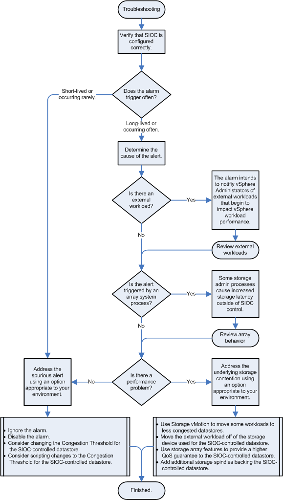
Flowchart for Troubleshooting

Using ESXi with iSCSI SANs

What is ISCSi?

iSCSI SANs use Ethernet connections between computer systems, or host servers, and high performance storage subsystems. The SAN components include iSCSI host bus adapters (HBAs) or Network Interface Cards (NICs) in the host servers, switches and routers that transport the storage traffic, cables, storage processors (SPs), and storage disk systems.
iSCSI SAN uses a client-server architecture. The client, called iSCSI initiator, operates on your host. It initiates iSCSI sessions by issuing SCSI commands and transmitting them, encapsulated into iSCSI protocol, to a server.
The server is known as an iSCSI target. The iSCSI target represents a physical storage system on the network. It can also be provided by a virtual iSCSI SAN, for example, an iSCSI target emulator running in a virtual machine. The iSCSI target responds to the initiator’s commands by transmitting required iSCSI data.

Ports

A single discoverable entity on the iSCSI SAN, such as an initiator or a target, represents an iSCSI node. Each node has one or more ports that connect it to the SAN.
iSCSI ports are end-points of an iSCSI session. Each node can be identified in a number of ways.

IP Address

Each iSCSI node can have an IP address associated with it so that routing and
switching equipment on your network can establish the connection between
the server and storage. This address is just like the IP address that you assign
to your computer to get access to your company’s network or the Internet.

iSCSI Name

A worldwide unique name for identifying the node. iSCSI uses the iSCSI
Qualified Name (IQN) and Extended Unique Identifier (EUI).
By default, ESXi generates unique iSCSI names for your iSCSI initiators, for
example, iqn.1998-01.com.vmware:iscsitestox-68158ef2. Usually, you do not
have to change the default value, but if you do, make sure that the new iSCSI
name you enter is worldwide unique.

ISCSI Alias

A more manageable name for an iSCSI device or port used instead of the iSCSI
name. iSCSI aliases are not unique and are intended to be just a friendly name
to associate with a port.

ISCSi Initiators

To access iSCSI targets, your host uses iSCSI initiators. The initiators transport SCSI requests and responses, encapsulated into the iSCSI protocol, between the host and the iSCSI target.
Your host supports different types of initiators.

Software Initiator

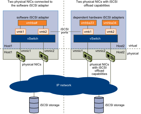
A software iSCSI adapter is a VMware code built into the VMkernel. It allows your host to connect to the iSCSI storage device through standard network adapters. The software iSCSI adapter handles iSCSI processing while communicating with the network adapter. With the software iSCSI adapter, you can use iSCSI technology without purchasing specialized hardware.

This requires VMkernel networking

Hardware Initiator

A hardware iSCSI adapter is a third-party adapter that offloads iSCSI and network processing from your host.
Hardware iSCSI adapters are divided into categories

  • Dependent Hardware iSCSI Adapter. This requires VMkernel networking

This type of adapter can be a card that presents a standard network adapter and iSCSI offload functionality for the same port. The iSCSI offload functionality depends on the host’s network configuration to obtain the IP, MAC, and other parameters used for iSCSI sessions. An example of a dependent adapter is the iSCSI licensed Broadcom 5709 NIC.

  • Independent Hardware iSCSI Adapter. No VMkernel networking needed

Implements its own networking and iSCSI configuration and management interfaces.
An example of an independent hardware iSCSI adapter is a card that either presents only iSCSI offload functionality or iSCSI offload functionality and standard NIC functionality. The iSCSI offload functionality has independent configuration management that assigns the IP, MAC, and other parameters used for the iSCSI sessions. An example of a independent adapter is the QLogic QLA4052 adapter. Hardware adapters may need to be licensed or they will not appear in the vClient or VCLI

CHAP

iSCSI storage systems authenticate an initiator by a name and key pair. ESXi supports the CHAP protocol, which VMware recommends for your SAN implementation. To use CHAP authentication, the ESXi host and the iSCSI storage system must have CHAP enabled and have common credentials.

Because the IP networks that the iSCSI technology uses to connect to remote targets do not protect the data they transport, you must ensure security of the connection. One of the protocols that iSCSI implements is the Challenge Handshake Authentication Protocol (CHAP), which verifies the legitimacy of initiators that access targets on the network.
CHAP uses a three-way handshake algorithm to verify the identity of your host and, if applicable, of the iSCSI target when the host and target establish a connection. The verification is based on a predefined private value, or CHAP secret, that the initiator and target share. ESXi supports CHAP authentication at the adapter level. In this case, all targets receive the same CHAP name and secret from the iSCSI initiator. For software and dependent hardware iSCSI adapters, ESXi also supports per-target CHAP authentication, which allows you to configure different credentials for each target to achieve greater level of security.

ESXi supports the following CHAP authentication methods:

  • One-way CHAP

In one-way CHAP authentication, also called unidirectional, the target authenticates the initiator, but the initiator does not authenticate the target.

  • Mutual CHAP

In mutual CHAP authentication, also called bidirectional, an additional level of security enables the initiator to authenticate the target. VMware supports this method for software and dependent hardware iSCSI adapters only.

For software and dependent hardware iSCSI adapters, you can set one-way CHAP and mutual CHAP for each initiator or at the target level. Independent hardware iSCSI supports CHAP only at the initiator level.

Security Levels

When you set the CHAP parameters, specify a security level for CHAP.

  • Do not use CHAP (Software/Dependent/Independent)
  • Do not use CHAP unless required by target (Software/Dependent)
  • Do not use CHAP unless prohibited by target (Software/Dependent/Independent)
  • Use CHAP (Software/Dependent)

vSphere: Storage vMotion Fails with an Operation Timed Out Error

You may experience these symptoms

  1. Storage vMotion fails
  2. The Storage vMotion operation fails with a timeout between 5-10% or 90-95% complete
  3. On ESX 4.1 you may see the errors:

Hostd Log

v ix: [7196 foundryVM.c:10177]: Error VIX_E_INVALID_ARG in VixVM_CancelOps(): One of the parameters was invalid ‘vm:/vmfs/volumes/4e417019-4a3c4130-ed96-a4badb51cd0a/Mail02/Mail02.vmx’ opID=9BED9F06-000002BE-9d] Failed to unset VM medatadata: FileIO error: Could not find file : /vmfs/volumes/4e417019-4a3c4130-ed96-a4badb51cd0a/Mail02/Mail02-aux.xml.tmp.

vmkernel: 114:03:25:51.489 cpu0:4100)WARNING: FSR: 690: 1313159068180024 S: Maximum switchover time (100 seconds) reached. Failing migration; VM should resume on source.
vmkernel: 114:03:25:51.489 cpu2:10561)WARNING: FSR: 3281: 1313159068180024 D: The migration exceeded the maximum switchover time of 100 second(s). ESX has preemptively failed the migration to allow the VM to continue running on the source host.
vmkernel: 114:03:25:51.489 cpu2:10561)WARNING: Migrate: 296: 1313159068180024 D: Failed: Maximum switchover time for migration exceeded(0xbad0109) @0x41800f61cee2

vCenter Log

[yyyy-mm-dd hh:mm:ss.nnn tttt error ‘App’] [MIGRATE] (migrateidentifier) vMotion failed: vmodl.fault.SystemError
[yyyy-mm-dd hh:mm:ss.nnn tttt verbose ‘App’] [VpxVmomi] Throw vmodl.fault.SystemError with:
(vmodl.fault.SystemError) {
dynamicType = ,
reason = “Source detected that destination failed to resume.”,
msg = “A general system error occurred: Source detected that destination failed to resume.”

Resolution

Note: A virtual machine with many virtual disks might be unable to complete a migration with Storage vMotion. The Storage vMotion process requires time to open, close, and process disks during the final copy phase. Storage vMotion migration of virtual machines with many disks might timeout because of this per-disk overhead.

This timeout occurs when the maximum amount of time for switchover to the destination is exceeded. This may occur if there are a large number of provisioning, migration, or power operations occurring on the same datastore as the Storage vMotion. The virtual machine’s disk files are reopened during this time, so disk performance issues or large numbers of disks may lead to timeouts.

The default timeout is 100 seconds, and can be modified by changing the fsr.maxSwitchoverSeconds option in the virtual machine configuration to a larger value. This change must be done with the virtual machine powered down.

To modify the fsr.maxSwitchoverSeconds option using the vSphere Client:

  1. Open vSphere Client and connect to the ESX/ESXi host or to vCenter Server.
  2. Locate the virtual machine in the inventory.
  3. Power off the virtual machine.
  4. Right-click the virtual machine and click Edit Settings.
  5. Click the Options tab.
  6. Select the Advanced: General section.
  7. Click the Configuration Parameters button.
  8. From the Configuration Parameters window, click Add Row
  9. In the Name field, enter the parameter name: fsr.maxSwitchoverSeconds
  10. In the Value field, enter the new timeout value in seconds (for example:300
  11. Click the OK buttons twice to save the configuration change.
  12. Power on the VM
To modify the fsr.maxSwitchoverSeconds option by editing the .vmx file manually:

The virtual machine’s configuration file can be manually edited to add or modify the option. Add the option on its own line fsr.maxSwitchoverSeconds = 300

Note: To edit a virtual machines configuration file you will need to power off the virtual machine, remove it from Inventory, make the changes to the vmx file, add the virtual machine back to inventory, and power the virtual machine on again.

Virtual Disk Formats

The distinguishing factor among virtual disk formats is how data is zeroed out for the boundary of the virtual disk file. Zeroing out can be done either at run time (when the write happens to that area of the disk) or at the disk’s creation time.

There are three main virtual disk formats within VMware vSphere

  1. Zeroedthick (Lazy)
  2. Eagerzeroedthick.
  3. Thin

1. Zeroedthick – The “zeroedthick” format is the default and quickly creates a “flat” virtual disk file. The Zeroed Thick option is the pre-allocation of the entire boundary of the VMDK disk when it is created. This is the traditional fully provisioned disk format. In the vSphere Client, this is the default option. The virtual disk is allocated all of its provisioned space and immediately made accessible to the virtual machine.  A lazy zeroed disk is not zeroed up front which makes the provisioning very fast. However, because each block is zeroed out before it is written to for the first time there is added latency on first write.

2. Eagerzeroed  -This pre-allocates the disk space as well as each block of the file being pre-zeroed within the VMDK. Because of the increased I/O requirement, this requires additional time to write out the VMDK but eliminates the zeroing later on . Finally, the “eagerzeroedthick” format is used/required by VMware’s new Fault Tolerance (FT) feature

3. Thin – The thin virtual disk format is perhaps the easier option to understand. This is simply an as-used consumption model. This disk format is not pre-written to disk and is not zeroed out until run time

Performance Differences

So, why is this important? For one, there may be a perceived performance implication of having the disks thin provisioned. The thin provisioning white paper by VMware explains with more detail how each of these formats are used, as well as a quantification of the performance differences of eager zeroed thick and other formats. The white paper states that the performance impact is negligible for thin provisioning, and in all situations the results are nearly indistinguishable.

http://www.vmware.com/pdf/vsp_4_thinprov_perf.pdf

VMware RDMs

What is RAW Device Mapping?

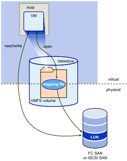
A Raw Device Mapping allows a special file in a VMFS volume to act as a proxy for a raw device. The mapping file contains metadata used to manage and redirect disk accesses to the physical device. The mapping file gives you some of the advantages of a virtual disk in the VMFS file system, while keeping some advantages of direct access to physical device characteristics. In effect it merges VMFS manageability with raw device access

A raw device mapping is effectively a symbolic link from a VMFS to a raw LUN. This makes LUNs appear as files in a VMFS volume. The mapping file, not the raw LUN is referenced in the virtual machine configuration. The mapping file contains a reference to the raw LUN.

Note that raw device mapping requires the mapped device to be a whole LUN; mapping to a partition only is not supported.

Uses for RDM’s

  • Use RDMs when VMFS virtual disk would become too large to effectively manage.

For example, When a VM needs a partition that is greater than the VMFS 2 TB limit is a reason to use an RDM. Large file servers, if you choose to encapsulate them as a VM, are a prime example. Perhaps a data warehouse application would be another. Alongside this, the time it would take to move a vmdk larger than this would be significant.

  • Use RDMs to leverage native SAN tools

SAN snapshots, direct backups, performance monitoring, and SAN management are all possible reasons to consider RDMs. Native SAN tools can snapshot the LUN and move the data about at a much quicker rate.

  • Use RDMs for virtualized MSCS Clusters

Actually, this is not a choice. Microsoft Clustering Services (MSCS) running on VMware VI require RDMs. Clustering VMs across ESX hosts is still commonly used when consolidating hardware to VI. VMware now recommends that cluster data and quorum disks be configured as raw device mappings rather than as files on shared VMFS

Terminology

The following terms are used in this document or related documentation:

  • Raw Disk — A disk volume accessed by a virtual machine as an alternative to a virtual disk file; it may or may not be accessed via a mapping file.
  • Raw Device — Any SCSI device accessed via a mapping file. For ESX Server 2.5, only disk devices are supported.
  • Raw LUN — A logical disk volume located in a SAN.
  • LUN — Acronym for a logical unit number.
  • Mapping File — A VMFS file containing metadata used to map and manage a raw device.
  • Mapping — An abbreviated term for a raw device mapping.
  • Mapped Device — A raw device managed by a mapping file.
  • Metadata File — A mapping file.
  • Compatibility Mode — The virtualization type used for SCSI device access (physical or virtual).
  • SAN — Acronym for a storage area network.
  • VMFS — A high-performance file system used by VMware ESX Server.

Compatibility Modes

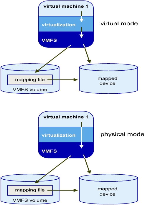
Physical Mode RDMs

  • Useful if you are using SAN-aware applications in the virtual machine
  • Useful to run SCSI target based software
  • Physical mode is useful to run SAN management agents or other SCSI target based software in the virtual machine
  • Physical mode for the RDM specifies minimal SCSI virtualization of the mapped device, allowing the greatest flexibility for SAN management software. In physical mode, the VMkernel passes all SCSI commands to the device, with one exception: the REPORT LUNs command is virtualized, so that the VMkernel can isolate the LUN for the owning virtual machine. Otherwise, all physical characteristics of the underlying hardware are exposed.

Virtual Mode RDMs

  • Advanced file locking for data protection
  • VMware Snapshots
  • Allows for cloning
  • Redo logs for streamlining development processes
  • More portable across storage hardware, presenting the same behavior as a virtual disk file

Setting up RDMs

  •  Right click on the Virtual Machine and select Edit Settings
  • Under the Hardware Tab, click Add
  • Select Hard Disk
  • Click Next
  • Click Raw Device Mapping

If the option is greyed out, please check the following.

http://kb.vmware.com/RDM Greyed Out

  • From the list of SAN disks or LUNs, select a raw LUN for your virtual machine to access directly.
  • Select a datastore for the RDM mapping file. You can place the RDM file on the same datastore where your virtual machine configuration file resides,
    or select a different datastore.
  • Select a compatibility mode. Physical or Virtual
  • Select a virtual device node
  • Click Next.
  • In the Ready to Complete New Virtual Machine page, review your selections.
  • Click Finish to complete your virtual machine.

Note: To use vMotion for virtual machines with enabled NPIV, make sure that the RDM files of the virtual machines are located on the same datastore. You cannot perform Storage vMotion or vMotion between datastores when NPIV is enabled.

What machines can you “not” Storage vMotion

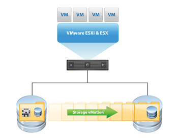
VMware Storage VMotion is a component of VMware vSphere™that provides an intuitive interface for live migration of virtual machine disk files within and across storage arrays with no downtime or disruption in service. Storage VMotion relocates virtual machine disk files from one shared storage location to another shared storage location with zero downtime, continuous service availability and complete transaction integrity. StorageVMotion enables organizations to perform proactive storage migrations, simplify array migrations, improve virtual machine storage performance and free up valuable storage capacity.Storage VMotion is fully integrated with VMware vCenter Server to provide easy migration and monitoring.

How does it work

1. Before moving a virtual machines disk file, Storage VMotion moves the “home directory” of the virtual machine to the new location. The home directory contains meta data about the virtual machine (configuration, swap and log files).

2. After relocating the home directory, Storage VMotion copies the contents of the entire virtual machine storage disk file to the destination storage host, leveraging “changed block tracking” to maintain data integrity during the migration process.

3. Next, the software queries the changed block tracking module to determine what regions of the disk were written to during the first iteration, and then performs a second iteration of copy, where those regions that were changed during the first iteration copy (there can be several more iterations).

4. Once the process is complete, the virtual machine is quickly suspended and resumed so that it can begin using the virtual machine home directory and disk file on the destination datastore location.

5. Before VMware ESX allows the virtual machine to start running again, the final changed regions of the source disk are copied over to the destination and the source home and disks are removed.

What machines can you not Storage vMotion?

1. Virtual machines with snapshots cannot be migrated using Storage vMotion

2. Migration of virtual machines during VMware Tools installation is not supported

3. The host on which the virtual machine is running must have a license that includes Storage vMotion.

4. ESX/ESXi 3.5 hosts must be licensed and configured for vMotion. ESX/ESXi 4.0 and later hosts do not require vMotion configuration in order to perform migration with Storage vMotion.

5. The host on which the virtual machine is running must have access to both the source and target datastores

6. Virtual machine disks in non-persistent mode cannot be migrated

7. Clustered applications or clustered virtual machine configurations do not support Storage vMotion.

8. For vSphere 4.0 and higher, Virtual Disks and Virtual RDM pointer files can be relocated to a destination datastore, and can be converted to thick provisioned or thin provisioned disks during migration as long as the detsination is not an NFS Datastore

9. Physical Mode Pointer files can be relocated to the destination datastore but cannot be converted

VMFS Block Sizes

VMFS-3

VMFS-3 Block Sizes are assigned to Datastores when created and determine the maximum file size that can be stored.

Here are the VMFS-3 Block sizes and corresponding file sizes

1MB = 256GB

2MB = 512GB

4MB = 1TB

8MB = 2TB

Once set this cannot be changed.

Sub-block allocation size

64KB

VMFS-5

Only hosts running ESXi 5 or later support VMFS-5. Hosts running ESXi 4.x will not be able to see or access VMFS-5 Datastores

VMFS-5 Datastores can be up to 64TB on a single extent

Datastores built on extents are still limited to 64TB as well.

Here is the VMFS-5 Block sizes and corresponding file size

1MB = 2TB

Sub-block allocation size

8KB

Adding Extents to Disks

vSphere 4 uses VMFS version 3 (VMFS-3) and vSphere 5 continues to provide support for VMFS-3.

VMFS-3 supports datastores with a maximum size of 2TB -512Bytes) This size stems from the partition management features which use MBR (Master Boot Record) instead of GPT (GUID Partition Tables)

So what happens if you need a larger datastore on a VMFS-3 datastore?

Fortunately VMFS-3 has the ability to reside on one or more partitions which are also known as extents.

VMFS-3 supports up to 32 extents in a single VMFS-3 Datastore with a maximum size of 64TB

For a VMFS volume, there is a rule of one VMFS per LUN. SCSI-2 Reservation locking in ESX locks the entire LUN and not a specific partition. Therefore, the best practice is to have one LUN per VMFS only (exception being local storage). When using extents, gather multiple LUNs under one logical VMFS and not multiple partitions per LUN.

Note: Ensure a complete rescan is done on all ESX hosts after adding an extent to a VMFS volume on one ESX host. Otherwise, the same extent might be inadvertently added by another node in the cluster, which could potentially cause loss of data. Best practice is to add extents to an existing VMFS volume from a single node and then rescan the storage resources from all ESX hosts capable of accessing that shared storage resource.

How to Extend a VMFS Datastore
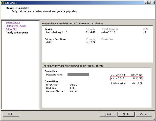
How to create a single VMFS datastore and increase the size by adding an extent.

First of all make sure you have created a new LUN on your storage or SAN and rescanned in VMware so all hosts can see the new storage

1. Select your datastore in the Datastore inventory.
2. Click Configurations tab.
3. In Datastore Details pane, click Properties link.
4. Click Increase on the Properties dialog box.
5. Do the following when prompted by the Increase Datastore Capacity wizard (field):
a. Select your LUN ID. (Extent Device)
b. Review current disk layout. (Current Disk Layout)
c. Leave the Maximum capacity check box selected. (Capacity)
d. Click Finish. (Ready to Complete)

Errors

When going through the Add Extent wizard on a datastore residing on a LUN that has already been extended at the hardware/array level you may receive a warning message indicating that there may be data loss.

The warning message is as follows:

Warning: The current disk layout will be destroyed.  All file systems and data will be lost permanently

This error message is in relation to the area of the disk that you are extending to, not the area of the disk you are extending from.

If you look in Target Identifier, you see the vmhba:W:X:Y:Z where the extent is to be placed. If your original disk was vmhba1:0:0:1 , that extent is created on vmhba:1:0:0:2

N_Port ID Virtualization Explained

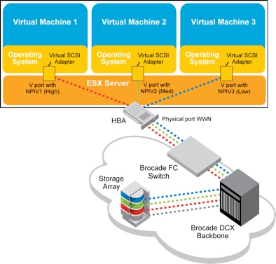
NPIV was initially developed by Emulex, IBM, and McDATA (now Brocade) to provide more scalable access to Fibre Channel storage from mainframe Linux Virtual Machine instances by allowing the assignment of a virtual WWN to each Linux OS partition.

N_Port ID Virtualization or NPIV is a Fibre Channel facility allowing multiple N_Port IDs to share a single physical N_Port. This allows multiple Fibre Channel initiators to occupy a single physical port, easing hardware requirements in Storage Area Network design, especially where virtual SANs are called for. NPIV is defined by the Technical Committee T11 in the Fibre Channel – Link Services (FC-LS) specification

With NPIV in place you can create a zone in a SAN that only one virtual machine can access, thus restoring that security between the applications even if they are both running on the same virtual machine

NPIV really pays off in a virtual environment because the virtual WWN follows the virtual machine. This means if you migrate the virtual machine from one host to another, there are no special requirements to make sure the target host has the correct access to the LUN. The virtual machine has that access and as a result the host inherits the ability to access it.

This greatly simplifies storage provisioning and zoning in a virtual environment by allowing the storage admin to interact with the lowest level of granularity in storage access. Once in place the storage admin can monitor SAN utilization statistics to track how each virtual machine is using SAN resources. With this level of detail the SAN administrator is better able to balance utilization.

What is required for NPIV?

To enable NPIV in the environment requires several components, the first of which is a NPIV aware fabric. The switches in the SAN must all support NPIV and again using Brocade as an example, all Brocade FC switches running Fabric OS (FOS) 5.1.0 or later support NPIV.

In addition the HBA’s must support NPIV as well and they need to expose an API for the VM monitor to create and manage the virtual fabric ports; it is relatively common for HBA’s to support this today.

Finally the virtualization software itself must support NPIV and be able to manage the relationship between the virtual NPIV ports and the virtual machines. Most virtualization software also requires the use of a specific type of disk mapping; VMware calls this Raw Disk Mapping (RDM).

In the VMware case, by default when a virtual machine is created it is mapped to a virtual disk in a Virtual Machine File System (VMFS). When the operating system inside the virtual machine issues disk access commands to the virtual disk, the virtualization hypervisor translates this to a VMFS file operation. RDMs are an alternative to VMFS. They are special files within a VMFS volume that act as a proxy for a raw device.

RDM gives some of the advantages of a virtual disk in the VMFS file system while keeping some advantages of direct access to physical devices. In addition to being used in a virtual environment with NPIV, RDM might be required if you use server clustering, or for better SAN snapshot control or some other layered application in the virtual machine. RDMs better enable systems to use the hardware features inherent to SAN arrays and the SAN fabric, NPIV being an example.

NPIV is completely transparent to disk arrays, so the storage systems themselves require no special support.

Runtime name format explained for a FC Storage Device

Runtime Name

The name of the first path to the device. The runtime name is created by the host. The name is not a reliable identifier for the device, and is not persistent.
The runtime name has the following format:

vmhba#:C#:T#:L#

  • vmhba# is the name of the storage adapter. The name refers to the physical adapter on the host, not to the SCSI controller used by the virtual machines.
  • C# is the storage channel number.
  • T# is the target number. Target numbering is decided by the host and might change if there is a change in the mappings of targets visible to the host. Targets that are shared by different hosts might not have the same target number.
  • L# is the LUN number that shows the position of the LUN within the target. The LUN number is provided by the storage system. If a target has only one LUN, the LUN number is always zero (0).

For example, vmhba1:C0:T3:L1 represents LUN1 on target 3 accessed through the storage adapter vmhba1 and channel 0.