Archive for Networking

Using tcpdump

What is tcpdump?

tcpdump is a network capture and protocol analysis tool (www.tcpdump.org). This program is based on the libpcap interface, a library for user-level network datagram capture. tcpdump can also be used to capture non-TCP traffic, including UDP and ICMP. The tcpdump program is native to Linux and ships with many distributions of BSD, Linux, and Mac OS X however, there is a Windows version.

Where is tcpdump installed?

You can check whether tcpdump is installed on your system with the following command

rhian@LAPTOP-KNJ4ALF8:~$ which tcpdump
/usr/sbin/tcpdump

How long does tcpdump run for?

tcpdump will keep capturing packets until it receives an interrupt signal. You can interrupt capturing by pressing Ctrl+C. To limit the number of packets captured and stop tcpdump, use the -c (for count) option.

When tcpdump finishes capturing packets, it will report counts of

  • Packets “captured” (this is the number of packets that tcpdump has received and processed)
  • Packets “received by filter” (This depends on the OS where you’re running tcpdump, and possibly on the way the OS was configured – if a filter was specified on the command line, then on some OSes it counts packets regardless of whether they were matched by the filter expression and, even if they were matched by the filter expression, regardless of whether tcpdump has read and processed them yet, on other OSes it counts only packets that were matched by the filter expression regardless of whether tcpdump has read and processed them yet, and on other OSes it counts only packets that were matched by the filter expression and were processed by tcpdump)
  • Packets “dropped by kernel” (this is the number of packets that were dropped, due to a lack of buffer space by the packet capture mechanism in the OS on which tcpdump is running. It depends if the OS reports that information to applications; if not, it will be reported as 0).

Writing a tcpdump output to file

When running tcpdump, the output file generated by the –w switch is not a text file and can only be read by tcpdump or another piece of software such as Wireshark which can parse the binary file format

tcpdump manual

https://www.tcpdump.org/manpages/tcpdump.1.html

Common Parameters

There are many more parameters but these are likely to be the most common ones.

ParameterExplanation
-#A packet number is printed on every line.
-cExit the dump after the specified number of packets.
-DPrint all available interfaces for capture.
Use ifconfig to check what interfaces you have
-ePrint also the link-layer header of a packet (e.g., to see the vlan tag).
This can be used, for example, to print MAC layer addresses for protocols such as Ethernet and IEEE 802.11.
-i
–interface
Interface to dump from
-nDo not resolve the addresses to names (e.g., IP reverse lookup).
-nnDisable name resolution of both host names and port names
-v
-vv
-vvv
Verbose output in more and more detail
-wWrites the output to a file which can be opened in Wireshark for example
-xUse tcpdump -X to show output including ASCII and hex. This will making reading screen output easier
-rRead a file containing a previous tcpdump capture

Examples

Check the interfaces available

# sudo tcpdump -D
1.eth0
2.eth1
3.wifi0
4.any (Pseudo-device that captures on all interfaces)
5.lo [Loopback]

 Capture all packets in any interface

# sudo tcpdump --interface any

Capture packets for a specific host and output to a file

# sudo tcpdump -i any host <host_ip> -w /tmp/tcpdump.pcap

Filtering Packets for just source and destination IP addresses, ports and protocols, etc. icmp example below

# sudo tcpdump -i any -c5 icmp

Filtering packets by port numbers

sudo tcpdump -i any -c5 -nn port 80

Filter based on source or destination ip or hostname

sudo tcpdump -i any -c5 -nn src 192.168.10.125
sudo tcpdump -i any -c5 -nn dst 192.168.20.125

sudo tcpdump -i any -c5 -nn src techlabadc001.techlab.com
sudo tcpdump -i any -c5 -nn dst techlabdns002.techlab.com

Complex expressions

You can also combine filters by using the logical operators and and or to create more complex expressions. For example, to filter packets from source IP address 192.168.10.125 and proocol HTTP only, use this command.

sudo tcpdump -i any -c5 -nn src 192.168.10.125 and port 80

You can create even more complex expressions by grouping filter with parentheses. Enclose the filter expression with quotation marks which prevents the shell from confusing them with shell expressions

sudo tcpdump -i any -c5 -nn "port 80 and (src 192.168.10.125 or src 10.168.10.20.125)"

Occasionally, we need even more visibility and inspection of the contents of the packets is required to ensure that the message we’re sending contains what we need or that we received the expected response. To see the packet content, tcpdump provides two additional flags: -X to print content in hex, and ASCII or -A to print the content in ASCII.

sudo tcpdump -i any -c20 -nn -A port 80

Reading and writing to a file

tcpdump has the ability to save the capture to a file so you can read and analyze the results later. This allows you to capture packets in batch mode overnight, for example, and verify the results at your leisure. It also helps when there are too many packets to analyze since real-time capture can occur too fast. If you have Wireshark installed, you can open the .pcap files in here for further analysis as well.

# Writing the file 
sudo tcpdump -i any -c10 -nn -w dnsserver.pcap port 53
# And to read the file
tcpdump -nn -r dnsserver.pcap

Summary

tcpdump and Wireshark are extremely useful tools to have to hand for troubleshooting network issues in more details. For example, we have used tcpdump to check whether outbound traffic from a host can ping a key management server or to check connectivity between a host and a syslog server over TCP port 514. Sometimes you may have to run these tools as an elevated account which may not be possible and there are certain situations where you may get an error when you run tcpdump like

tcpdump: socket for SIOCETHTOOL(ETHTOOL_GET_TS_INFO): Socket type not supported

This can sometime happen where you may be using Windows Subsystem for Linux (WSL) which  allows you to install a complete Ubuntu terminal environment on your Windows machine. There is some functionality not enabled quite yet which will restrict certain things you want to do.
HP Virtual Connect Flex 10 Technology

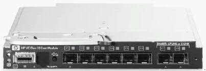
Virtual Connect Flex-10 technology is a hardware based solution that enables server administrators to partition each 10 gigabit Ethernet port into 4 and regulate the data speed of each partition. HP Flex-10 technology is available only with Virtual Connect (VC).

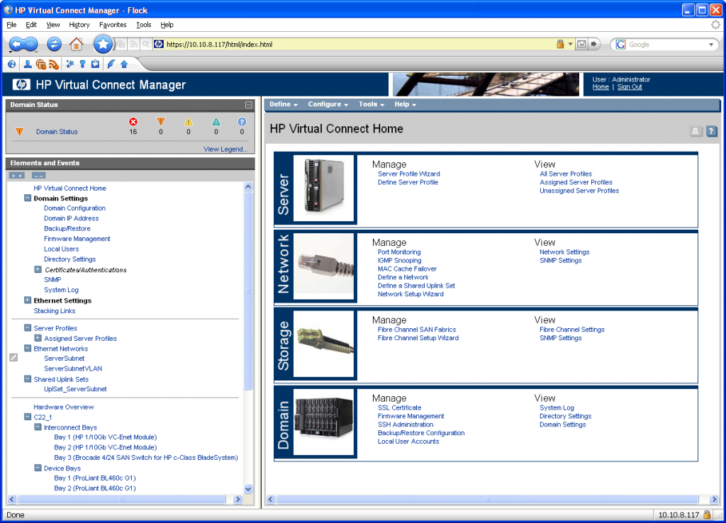
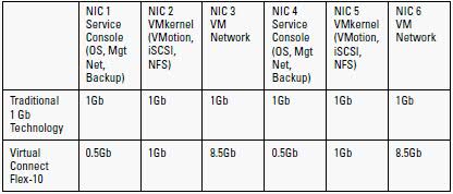
The Virtual Connect Flex-10 feature set enables VC to configure a single 10Gb network port of BladeSystem servers to represent four physical NIC devices, also called FlexNICs, with a total bandwidth of 10Gbps. These four FlexNICs appear to the operating system (OS) as discrete network interface controllers (NIC), each with its own driver. While the FlexNICs share the same physical port, traffic flow for each one is isolated with its own MAC address and virtual local area network (VLAN) tags between the FlexNIC and VC Flex-10 interconnect module. The bandwidth available to each FlexNIC is controlled by the server administrator through the Virtual Connect Manager interface.

Advantages

Advantages from using Flex-10 technology are significant.

  • The implementation cost and management burden of 10GbE infrastructure become more feasible.
  • It is easier to aggregate multiple 1Gb data flows and fully utilize 10Gb bandwidth.
  • The ability to adjust bandwidth for partitioned data flow is more cost efficient and easier to manage.
  • The fact that Virtual Connect Flex-10 is hardware based but designed to compliment VC technologies, means that multiple FlexNICs are added without the additional processor overhead or latency associated with virtualization or soft switches.
  • Significant infrastructure savings are also realized since additional server NIC’s and associated switches may not be needed.
  • Each dual-port Flex-10 NIC supports up to 8 FlexNIC’s and each Flex-10 Interconnect Module can support up to 64 FlexNIC’s. Other switch options only support 16 NIC’s per model.
  • There are 2 available mezzanine slots in each blade for future expansion and 6 available I/O module slots in the enclosurfor future expansion
  • Instead of putting the burden of traffic throttling in software or the hypervisor, Flex 10 can do it in hardware

What does Virtual Connect Contain?

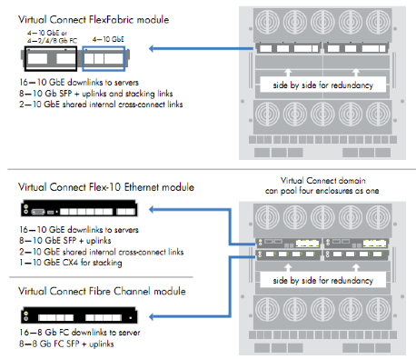
Virtual Connect is a set of interconnect modules and embedded software for HP BladeSystem c-Class enclosures that simplifies the setup and administration of server connections. HP Virtual Connect includes the following components:

  • HP 1/10Gb Virtual Connect Ethernet Module for c-Class BladeSystem
  • HP 1/10Gb-F Virtual Connect Ethernet Module for the c-Class BladeSystem
  • HP Virtual Connect Flex-10 10Gb Ethernet Module for BladeSystem c-Class
  • HP 4Gb Virtual Connect Fibre Channel Module for c-Class BladeSystem
  • HP Virtual Connect 4Gb Fibre Channel Module for BladeSystem c-Class (enhanced NPIV)
  • HP Virtual Connect Manager

How to access Virtual Connect

The Onboard Administrator for the HP BladeSystem c7000 enclosure is the brains of the new c-Class infrastructure. Together with the enclosure’s HP Insight Display, the Onboard Administrator has been designed for both local and remote administration of HP BladeSystem c-Class. This module and its firmware provides:

  • Wizards for simple, fast setup and configuration
  • Highly available and secure access to the HP Bladesystem infrastructure
  • Security roles for server, network, and storage administrators
  • Automated power and cooling of the HP Bladesystem infrastructure
  • Agent-less device health and status
  • Thermal Logic power and cooling information and control

Each c7000 enclosure is shipped with a first Onboard Administrator module/firmware. If desired, a customer may order a second redundant Onboard Administrator module for each enclosure. When two Onboard Administrator modules are present in a c7000 enclosure, they work in an active – standby mode, assuring full redundancy of the c7000’s integrated management.

Support Manual

http://h20000.www2.hp.com/bc/docs/support/SupportManual/c00865618/c00865618.pdf?jumpid=reg_R1002_USEN

Useful Links

http://virtualkenneth.com/2009/11/04/understanding-hp-flex-10-mappings-with-vmware/

http://up2v.files.wordpress.com/2010/04/hp-virtual-connect-for-dummies.pdf

IP Addressing and Subnet Masks

This comes up again and again and I wanted to write a post which tries to simplify this as much as possible as it’s continually been a useful skill to have as well as a reference when out and about if needed 🙂

An IP (Internet Protocol) address is a unique identifier for a node or host connection on an IP network. An IP address is a 32 bit binary number usually represented as 4 decimal values, each representing 8 bits, in the range 0 to 255 (known as octets) separated by decimal points. This is known as “dotted decimal” notation

Address classes

Class Description Binary Decimal No of Networks Number of addresses
A Universal Unicast 0xxx 1-126 27 = 128 224 = 16777216
B Universal Unicast 10xx 128-191 214 = 16384 216 = 65536
C Universal Unicast 110x 192-223 221 = 2097152 28 = 256
D Multicast 1110 224-239 tbc tbc
E Not used 1111 240-254 tbc tbc

Example

X is the network address and n is the node address on that network

Class Network and Node Address
A XXXXXXXX.nnnnnnnn.nnnnnnnn.nnnnnnnn
B XXXXXXXX.XXXXXXXX.nnnnnnnn.nnnnnnnn
C XXXXXXXX.XXXXXXXX.XXXXXXXX.nnnnnnnn

Private IP Addresses

These are non routable on the internet and are assigned as internal IP Addresses within a company/Private network

Address Range Subnet Mask
10.0.0.0 – 10.255.255.255 255.0.0.0
172.16.0.0 – 172.31.255.255 255.240.0.0
192.168.0.0 to 192.168.255.255 255.255.0.0

APIPA

APIPA is a DHCP failover mechanism for local networks. With APIPA, DHCP clients can obtain IP addresses when DHCP servers are non-functional. APIPA exists in all modern versions of Windows except Windows NT.

When a DHCP server fails, APIPA allocates IP addresses in the private range

169.254.0.1 to 169.254.255.254.

Clients verify their address is unique on the network using ARP. When the DHCP server is again able to service requests, clients update their addresses automatically.

Binary Finary

A major stumbling block to successful subnetting is often a lack of understanding of the underlying binary math. IP Addressing is based on the Power of 2 binary maths as seen below

x 2x 2x
0 20 1
1 21 2
2 22 4
3 23 8
4 24 16
5 25 32
6 26 64
7 27 128

An IP Address actually looks like the below when you write it out

10001100. 10110011.11011100.11001000

140 179 220 200
10001100 10110011 11011100 11001000

Each numerical value for the 8 1’s and 0’s can be seen in the table below. You have to add together each value in the top column where it is 1 in the octet to reach the binary address number.

So for E.g 140 above in the first octet

128 + 8+ 4 = 140

128 64 32 16 8 4 2 1
1 0 0 0 1 1 0 0

Subnet Masks

Subnetting an IP Network can be done for a variety of reasons, including organization, use of different physical media (such as Ethernet, FDDI, WAN, etc.), preservation of address space, and security. The most common reason is to control network traffic. In an Ethernet network, all nodes on a segment see all the packets transmitted by all the other nodes on that segment. Performance can be adversely affected under heavy traffic loads, due to collisions and the resulting retransmissions. A router is used to connect IP networks to minimize the amount of traffic each segment must receive

Applying a subnet mask to an IP address allows you to identify the network and node parts of the address. The network bits are represented by the 1s in the mask, and the node bits are represented by the 0s.

Default Subnet Masks

Class Address Binary Address
Class A 255.0.0.0 11111111.00000000.00000000.00000000
Class B 255.255.0.0 11111111.11111111.00000000.00000000
Class C 255.255.255.0 11111111.11111111.11111111.00000000

Performing a bitwise logical AND operation between the IP address and the subnet mask results in the Network Address or Number.

For example, using our test IP address and the default Class B subnet mask and doing the AND operation, we get

IP Address 10001100.10110011.11110000.11001000 140.179.220.200
Subnet Mask 11111111.11111111.00000000.00000000 255.255.0.0
Network Address 10001100.10110011.00000000.00000000      140.179.0.0

If both operands have nonzero values, the result has the value 1. Otherwise, the result has the value 0 so if both the IP Address and the subnet Mask have 1’s in the same part of the octet, the result is a 1. Convert to binary to find your network address.

Subnetting

In order to subnet a network, extend the natural mask using some of the bits from the host ID portion of the address to create a subnetwork ID. See the Submask row below in red

In this example we want to extend network address 204.17.5.0

IP Address 11001100.00010001.00000101.11001000 204.17.5.200
Subnet Mask 11111111.11111111.11111111.11100000 255.255.255.224
Network Address 11001100.00010001.00000101.00000000      204.17.5.0
Broadcast Address 11001100.00010001.00000101.11111111 204.17.5.255

In this example a 3 bit subnet mask was used. There are 8 (23)- 2 subnets available with this size mask however there are 2 taken for the network ID and Broadcast ID reserved addresses so 6 available subnets

The amount of bits left = 5 therefore the amount of usable addresses on this is (25)- 2 nodes = 30. (Remember that addresses with all 0’s and all 1’s are not allowed hence the -2).

So, with this in mind, these subnets have been created

Subnet addresses Host Addresses
204.17.5.0 / 255.255.255.224 1-30
204.17.5.32 / 255.255.255.224 33-62
204.17.5.64 / 255.255.255.224 65-94
204.17.5.96 / 255.255.255.224 97-126
204.17.5.128 / 255.255.255.224  129-158
204.17.5.160 / 255.255.255.224 161-190
204.17.5.192 / 255.255.255.224 193-222
204.17.5.224 / 255.255.255.224 225-254

CIDR Notation

Subnet Masks can also be described as slash notation as per below

Prefix Length in Slash Notation Equivalent Subnet Mask
/1 128.0.0.0
/2 192.0.0.0
/3 224.0.0.0
/4 240.0.0.0
/5 248.0.0.0
/6 252.0.0.0
/7 254.0.0.0
/8 255.0.0.0
/9 255.128.0.0
/10 255.292.0.0
/11 255.224.0.0
/12 255.240.0.0
/13 255.248.0.0
/14 255.252.0.0
/15 255.254.0.0
/16 255.255.0.0
/17 255.255.128.0
/18 255.255.192.0
/19 255.255.224.0
/20 255.255.240.0
/21 255.255.248.0.0
/22 255.255.252.0
/23 255.255.254.0
/24 255.255.255.0
/25 255.255.255.128
/26 255.255.255.192
/27 255.255.255.224
/28 255.255.255.240
/29 255.255.255.248
/30 255.255.255.252

Subnetting Tricks

1. How to work out your subnet range

Lets say you have a subnet Mask 255.255.255.240 (/28)

You need to do 256-240 = 16

Then your subnets are 0, 16, 32, 48, 64, 80, 96, 112, 128, 144, 160, 176, 192, 208, 224, 240

For the subnetwork 208 – 223 is the broadcast and 209-222 are the useable addresses on that subnet.