Archive for microsoft

Network Connectivity Status Indicator and Resulting Internet Communication in Windows 7 and Windows Server 2008 R2

NCIS

Windows® 7 and Windows Server® 2008 R2 include a feature called Network Connectivity Status Indicator (NCSI), which is part of a broader feature called Network Awareness. Network Awareness collects network connectivity information and makes it available through an application programming interface (API) to services and applications on a computer running Windows 7 or Windows Server 2008 R2. With this information, services and applications can filter networks (based on attributes and signatures) and choose the networks that are best suited to their tasks. Network Awareness notifies services and applications about changes in the network environment, thus enabling applications to dynamically update network connections.

Network Awareness collects network connectivity information such as the Domain Name System (DNS) suffix of the computer and the forest name and gateway address of networks that the computer connects to. When called on by Network Awareness, NCSI can add information about the following capabilities for a given network:

  • Connectivity to an intranet
  • Connectivity to the Internet (possibly including the ability to send a DNS query and obtain the correct resolution of a DNS name)

What you will see

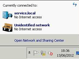
A yellow warning triangle in the System Tray looking like

and

What does Windows check, and in what order, before it announces that there are connectivity problems and displays the yellow triangle formed icon down at the task bar

Windows checks a Microsoft site for connectivity, using the Network Connectivity Status Indicator site.

  • NCSI sends a DNS lookup request for dns.msftncsi.com. This DNS address should resolve to 131.107.255.255. If the address does not match, then it is assumed that the internet connection is not functioning correctly.

The exact sequence of when which test is run is not documented; however, a little bit of digging around with a packet sniffing tool like Wireshark reveals some info.

It appears that on any connection, the first thing NCSI does is requests the text file (step 1 above). NCSI expects a 200 OK response header with the proper text returned. If the response is never received, or if there is a redirect, then a DNS request for dns.msftncsi.com is made. If DNS resolves properly but the page is inaccessible, then it is assumed that there is a working internet connection, but an in-browser authentication page is blocking access to the file. This results in the pop-up balloon above. If DNS resolution fails or returns the wrong address, then it is assumed that the internet connection is completely unsuccessful, and the “no internet access” error is shown.

The order of events appears to be slightly different depending on whether the wireless network is saved, has been connected to before even if it is not in the saved connections list, and possibly depending on the encryption type. The DNS and HTTP requests and responses showing up in Wireshark were not always consistent, even connecting to the same network, so it’s not entirely clear what causes different methods of detection under different scenario

Resolving this issue

  • http://technet.microsoft.com/en-us/library/ee126135%28v=ws.10%29.aspx
  • Check you can ping your DNS Servers
  • Check you can ping your Gateway
  • Check your server is listed correctly in DNS
  • Check DNS suffixes
  • Check proxy servers if you have any
  • Check your router
  • Check other servers have connection
  • Turn off the Indicator in Group Policy.
  • If everything checks out ok, Go into GPMC and Expand Computer Configuration, expand Administrative Templates, expand System, expand Internet Communication Management, and then click Internet Communication settings. In the details pane, double-click Turn off Windows Network Connectivity Status Indicator active tests, and then click Enabled
  • Change the Registry key to not query the server:  HKLM/system/currentcontrol
    set/services/nlasvc/parameters/internet – set enable activeprobing to 0
Remote Desktop Login always creates a temporary profile

Just a quick fix for this as this happened to me today and is a fairly annoying problem

Resolution

  • Log into server as an Administrative User
  • Start > Run regedit
  • [HKEY_LOCAL_MACHINE]\SOFTWARE\Microsoft\Windows NT\CurrentVersion\ProfileList
  • Delete the profile which is failing usually has a .bak extension
  • Try logging in again
  • Success

Setting up Network Load Balancing (2008 R2)

scales

For this post, I built 2 Test Virtual Machines called DACVNLB001 and DACVNLB002 to test setting up Network Load Balancing. These VMs are running Windows Server 2008 R2

  • Once your VMs are built, go into Server Manager or Initial Configuration Tasks and Click Add Features
  • Select Network Load Balancing > Next > Install (On Both Servers)
  • Reboot
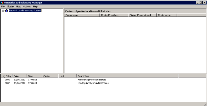
  • Open Network Load Balancing Manager on the first server

  • Right click Network Load Balancing Clusters and choose New Cluster. Put in the first server name

  •  Click Connect
  • Click Next

  • Priority is set to 1 because this is a new cluster and this is the first host in the cluster
  • Click Next. We are now on the Cluster IP Address Page. This must be a unique IP Address in the same network as the 2 NLB Nodes

  • Click OK and Next
  • Put a full internet name in and choose cluster operation node as Unicast (More described later on this

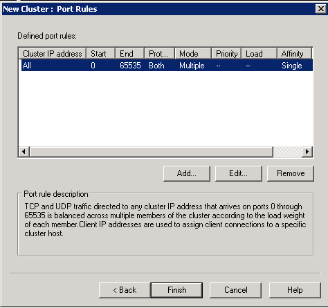
  • Click Finish on Port Rules

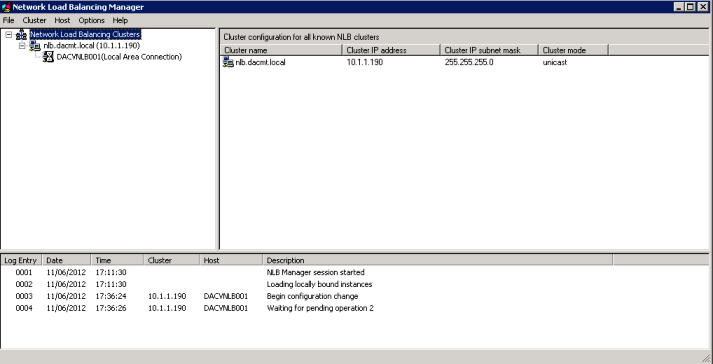
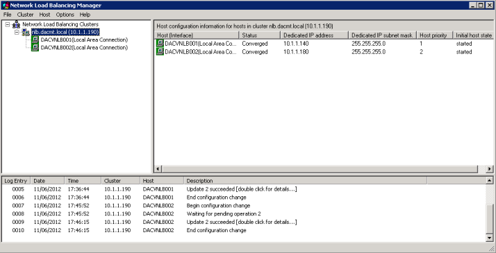
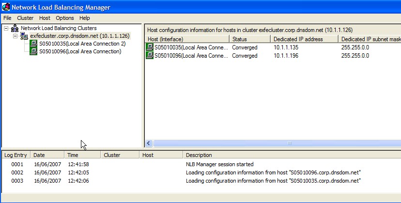
  • You should now see the below screen

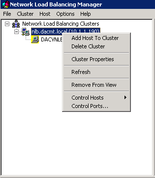
  •  Now we need to add the other host so right click your cluster name/IP Address in this case 10.1.1.190 and select Add Host to Cluster

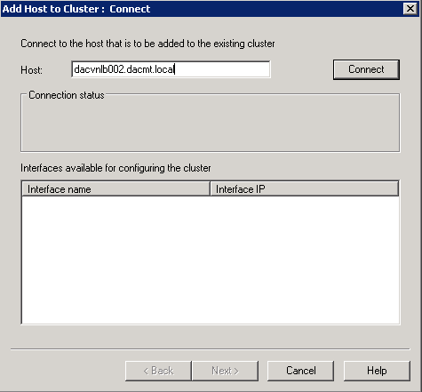
  •  Type in the 2nd node name

  • Click Connect
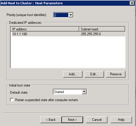
  •  Check the screen below is correct and click Next

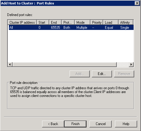
  •  Click Next on the Ports screen

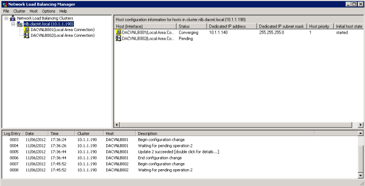
  • Wait for them to converge

  • You are Complete and should look like the below

 Unicast and Multicast

Applies To: Windows Server 2003, Windows Server 2003 R2, Windows Server 2003 with SP1, Windows Server 2003 with SP2

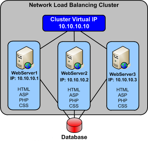
All cluster hosts in a cluster receive all incoming client requests that are destined for the virtual IP address that is assigned to the cluster. The Network Load Balancing load-balancing algorithm, which runs on each cluster host, is responsible for determining which cluster host processes and responds to the client request.

You can distribute incoming client requests to cluster hosts by using unicast or multicast methods. Both methods send the incoming client requests to all hosts by sending the request to the cluster’s MAC address.

When you use the unicast method, all cluster hosts share an identical unicast MAC address. Network Load Balancing overwrites the original MAC address of the cluster adapter with the unicast MAC address that is assigned to all the cluster hosts.

When you use the multicast method, each cluster host retains the original MAC address of the adapter. In addition to the original MAC address of the adapter, the adapter is assigned a multicast MAC address, which is shared by all cluster hosts. The incoming client requests are sent to all cluster hosts by using the multicast MAC address.

Select the unicast method for distributing client requests, unless only one network adapter is installed in each cluster host and the cluster hosts must communicate with each other. Because Network Load Balancing modifies the MAC address of all cluster hosts to be identical, cluster hosts cannot communicate directly with one another when using unicast. When peer-to-peer communication is required between cluster hosts, include an additional network adapter or select multicast mode. When the unicast method is inappropriate, select the multicast method

Selecting the Unicast Method

  • The cluster adapters for all cluster hosts are assigned the same unicast MAC address.
  • The outgoing MAC address for each packet is modified, based on the cluster host’s priority setting, to prevent upstream switches from discovering that all cluster hosts have the same MAC address.
  • The modification of the outgoing MAC address is appropriate for switches. When a hub is used to connect the cluster hosts, disable the modification of the outgoing MAC address. On Windows Server 2003, you can disable modification of outgoing addresses by setting the value of the registry entry MaskSourceMAC, of data type REG_DWORD, to 0x0. MaskSourceMAC is located in HKLM\SYSTEM\CurrentControlSet\Services\WLBS\Parameters\Interface\Adapter-GUID (where Adapter-GUID is the long GUID assigned to the network adapter in the server).
  • The unicast MAC address is derived from the cluster’s IP address to ensure uniqueness outside the cluster hosts.
  • Communication between cluster hosts, other than Network Load Balancing–related traffic (such as heartbeat), is only available when you install an additional adapter, because the cluster hosts all have the same MAC address.

Although the unicast method works in all routing situations, it has the following disadvantages:

  • A second network adapter is required to provide peer-to-peer communication between cluster hosts.
  • If the cluster is connected to a switch, incoming packets are sent to all the ports on the switch, which can cause switch flooding.

Selecting the Multicast Method

  • The cluster adapter for each cluster host retains the original hardware unicast MAC address (as specified by the hardware manufacture of the network adapter).
  • The cluster adapters for all cluster hosts are assigned a multicast MAC address.
  • The multicast MAC is derived from the cluster’s IP address.
  • Communication between cluster hosts is not affected, because each cluster host retains a unique MAC address

By using the multicast method with Internet Group Membership Protocol (IGMP), you can limit switch flooding, if the switch supports IGMP snooping. IGMP snooping allows the switch to examine the contents of multicast packets and associate a port with a multicast address. Without IGMP snooping, switches might require additional configuration to tell the switch which ports to use for the multicast traffic. Otherwise, switch flooding occurs, as with the unicast method.

The multicast method has the following disadvantages:

  • Upstream routers might require a static Address Resolution Protocol (ARP) entry. This is because routers might not accept an ARP response that resolves unicast IP addresses to multicast MAC addresses.
  • Without IGMP, switches might require additional configuration to tell the switch which ports to use for the multicast traffic.
  • Upstream routers might not support mapping a unicast IP address (the cluster IP address) with a multicast MAC address. In these situations, you must upgrade or replace the router. Otherwise, the multicast method is unusable.

Failover Clusters in Windows Server 2008 – Quorums

What is a cluster?

A failover cluster is a group of independent computers that work together to increase the availability of applications and services. The clustered servers (called nodes) are connected by physical cables and by software. If one of the cluster nodes fails, another node begins to provide service (a process known as failover). Users experience a minimum of disruptions in service.

Are there any special considerations?

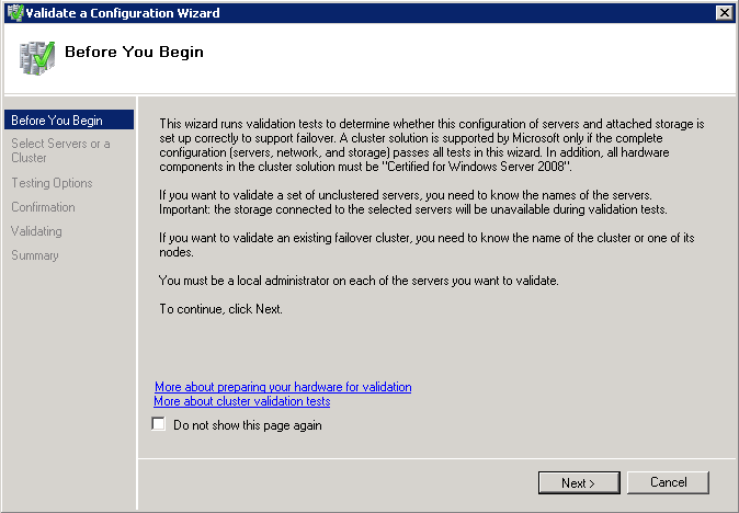
Microsoft supports a failover cluster solution only if all the hardware components are marked as “Certified for Windows Server 2008 R2.” In addition, the complete configuration (servers, network, and storage) must pass all tests in the Validate a Configuration wizard, which is included in the Failover Cluster Manager snap-in.

Note that this policy differs from the support policy for server clusters in Windows Server 2003, which required the entire cluster solution to be listed in the Windows Server Catalog under Cluster Solutions.

Cluster validation is intended to catch hardware or configuration problems before the cluster goes into production. Cluster validation helps to ensure that the solution you are about to deploy is truly dependable. Cluster validation can also be performed on configured failover clusters as a diagnostic tool.

Step by Step Guide

  • Run the cluster validation wizard for a failover cluster
  • If the cluster does not yet exist, choose the servers that you want to include in the cluster, and make sure you have installed the failover cluster feature on those servers. To install the feature, on a server running Windows Server 2008 or Windows Server 2008 R2, click Start, click Administrative Tools, click Server Manager, and under Features Summary, click Add Features. Use the Add Features wizard to add the Failover Clustering feature.
  • If the cluster already exists, make sure that you know the name of the cluster or a node in the cluster
  • For a planned cluster with all hardware connected: Run all tests.
  • For a planned cluster with parts of the hardware connected: Run System Configuration tests, Inventory tests, and tests that apply to the hardware that is connected (that is, Network tests if the network is connected or Storage tests if the storage is connected).
  • For a cluster to which you plan to add a server: Run all tests. Before you run them, be sure to connect the networks and storage for all servers that you plan to have in the cluster.
  • For troubleshooting an existing cluster: If you are troubleshooting an existing cluster, you might run all tests, although you could run only the tests that relate to the apparent issue.
  • In the failover cluster snap-in, in the console tree, make sure Failover Cluster Management is selected and then, under Management, click Validate a Configuration.

  • Follow the instructions in the wizard to specify the servers and the tests, and run the tests.
  • Note that when you run the cluster validation wizard on unclustered servers, you must enter the names of all the servers you want to test, not just one.
  • The Summary page appears after the tests run.
  • While still on the Summary page, click View Reportto view the test results.To view the results of the tests after you close the wizard, see SystemRoot\Cluster\Reports\Validation Report date and time.html where SystemRoot is the folder in which the operating system is installed (for example, C:\Windows)

Error Chart

Configuring the Quorum in a Failover Cluster

In simple terms, the quorum for a cluster is the number of elements that must be online for that cluster to continue running. In effect, each element can cast one “vote” to determine whether the cluster continues running. The voting elements are nodes or, in some cases, a disk witness or file share witness. Each voting element (with the exception of a file share witness) contains a copy of the cluster configuration, and the Cluster service works to keep all copies synchronized at all times

Note that the full function of a cluster depends not just on quorum, but on the capacity of each node to support the services and applications that fail over to that node. For example, a cluster that has five nodes could still have quorum after two nodes fail, but each remaining cluster node would continue serving clients only if it had enough capacity to support the services and applications that failed over to it.

Why Quorum is necessary

When network problems occur, they can interfere with communication between cluster nodes. A small set of nodes might be able to communicate together across a functioning part of a network, but might not be able to communicate with a different set of nodes in another part of the network. This can cause serious issues. In this “split” situation, at least one of the sets of nodes must stop running as a cluster.

To prevent the issues that are caused by a split in the cluster, the cluster software requires that any set of nodes running as a cluster must use a voting algorithm to determine whether, at a given time, that set has quorum. Because a given cluster has a specific set of nodes and a specific quorum configuration, the cluster will know how many “votes” constitutes a majority (that is, a quorum). If the number drops below the majority, the cluster stops running. Nodes will still listen for the presence of other nodes, in case another node appears again on the network, but the nodes will not begin to function as a cluster until the quorum exists again.

For example, in a five node cluster that is using a node majority, consider what happens if nodes 1, 2, and 3 can communicate with each other but not with nodes 4 and 5. Nodes 1, 2, and 3 constitute a majority, and they continue running as a cluster. Nodes 4 and 5 are a minority and stop running as a cluster, which prevents the problems of a “split” situation. If node 3 loses communication with other nodes, all nodes stop running as a cluster. However, all functioning nodes will continue to listen for communication, so that when the network begins working again, the cluster can form and begin to run.

Overview of the Quorum Nodes

There have been significant improvements to the quorum model in Windows Server 2008. In Windows Server 2003, almost all server clusters used a disk in cluster storage (the “quorum resource”) as the quorum. If a node could communicate with the specified disk, the node could function as a part of a cluster, and otherwise it could not. This made the quorum resource a potential single point of failure. In Windows Server 2008, a majority of ‘votes’ is what determines whether a cluster achieves quorum. Nodes can vote, and where appropriate, either a disk in cluster storage (called a “disk witness”) or a file share (called a “file share witness”) can vote. There is also a quorum mode called No Majority: Disk Only which functions like the disk-based quorum in Windows Server 2003. Aside from that mode, there is no single point of failure with the quorum modes, since what matters is the number of votes, not whether a particular element is available to vote.

This new quorum model is flexible and you can choose the mode best suited to your cluster.

Important: In most situations, it is best to use the quorum mode selected by the cluster software. If you run the quorum configuration wizard, the quorum mode that the wizard lists as “recommended” is the quorum mode chosen by the cluster software. We only recommend changing the quorum configuration if you have determined that the change is appropriate for your cluster.

There are four quorum modes:

  • Node Majority: Each node that is available and in communication can vote. The cluster functions only with a majority of the votes, that is, more than half.
  • Node and Disk Majority: Each node plus a designated disk in the cluster storage (the “disk witness”) can vote, whenever they are available and in communication. The cluster functions only with a majority of the votes, that is, more than half.
  • Node and File Share Majority: Each node plus a designated file share created by the administrator (the “file share witness”) can vote, whenever they are available and in communication. The cluster functions only with a majority of the votes, that is, more than half.
  • No Majority: Disk Only: The cluster has quorum if one node is available and in communication with a specific disk in the cluster storage.

Choosing the Quorum Mode for a particular cluster

Description of Cluster

Quorum Recommendation

Odd number of nodes

Node Majority

Even number of nodes (but not a multi-site cluster)

Node and Disk Majority

Even number of nodes, multi-site cluster

Node and File Share Majority

Even number of nodes, no shared storage

Node and File Share Majority

Node Majority

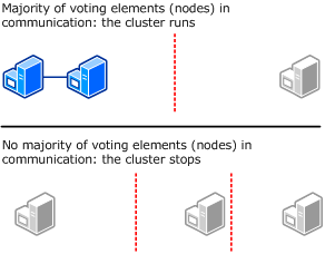
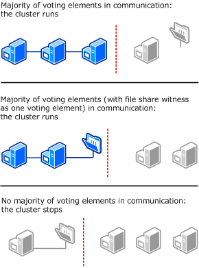
The following diagram shows Node Majority used (as recommended) for a cluster with an odd number of nodes.In this mode, each node gets one vote. In certain circumstances, you might want to install a hotfix that lets you select which nodes will have votes. This can be useful with certain multi-site clusters, for example, where you want one site to have more votes than other sites in a disaster recovery situation

Node and Disk Majority

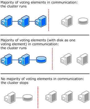
The following diagram shows Node and Disk Majority used (as recommended) for a cluster with an even number of nodes. Each node can vote, as can the disk witness.

  • Use a small Logical Unit Number (LUN) that is at least 512 MB in size.
  • Choose a basic disk with a single volume.
  • Make sure that the LUN is dedicated to the disk witness. It must not contain any other user or application data.
  • Choose whether to assign a drive letter to the LUN based on the needs of your cluster. The LUN does not have to have a drive letter (to conserve drive letters for applications).
  • As with other LUNs that are to be used by the cluster, you must add the LUN to the set of disks that the cluster can use. For more information, see http://go.microsoft.com/fwlink/?LinkId=114539.
  • Make sure that the LUN has been verified with the Validate a Configuration Wizard.
  • We recommend that you configure the LUN with hardware RAID for fault tolerance.
  • In most situations, do not back up the disk witness or the data on it. Backing up the disk witness can add to the input/output (I/O) activity on the disk and decrease its performance, which could potentially cause it to fail.
  • We recommend that you avoid all antivirus scanning on the disk witness.
  • Format the LUN with the NTFS file system.

If there is a disk witness configured, but bringing that disk online will not achieve quorum, then it remains offline. If bringing that disk online will achieve quorum, then it is brought online by the cluster software

Node and File Share Majority

The following diagram shows Node and File Share Majority used (as recommended) for a cluster with an even number of nodes and a situation where having a file share witness works better than having a disk witness. Each node can vote, as can the file share witness.

  • Use a Server Message Block (SMB) share on a Windows Server 2003 or Windows Server 2008 file server.
  • Make sure that the file share has a minimum of 5 MB of free space.
  • Make sure that the file share is dedicated to the cluster and is not used in other ways (including storage of user or application data).
  • Do not place the share on a node that is a member of this cluster or will become a member of this cluster in the future.
  • You can place the share on a file server that has multiple file shares servicing different purposes. This may include multiple file share witnesses, each one a dedicated share. You can even place the share on a clustered file server (in a different cluster), which would typically be a clustered file server containing multiple file shares servicing different purposes.
  • For a multi-site cluster, you can co-locate the external file share at one of the sites where a node or nodes are located. However, we recommend that you configure the external share in a separate third site.
  • Place the file share on a server that is a member of a domain, in the same forest as the cluster nodes.
  • For the folder that the file share uses, make sure that the administrator has Full Control share and NTFS permissions.
  • Do not use a file share that is part of a Distributed File System (DFS) Namespace

No Majority – Disk only

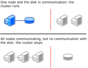
The following illustration shows how a cluster that uses the disk as the only determiner of quorum can run even if only one node is available and in communication with the quorum disk. It also shows how the cluster cannot run if the quorum disk is not available (single point of failure). For this cluster, which has an odd number of nodes, Node Majority is the recommended quorum mode.

  • Use a small Logical Unit Number (LUN) that is at least 512 MB in size.
  • Choose a basic disk with a single volume.
  • Make sure that the LUN is dedicated to the disk witness. It must not contain any other user or application data.
  • Choose whether to assign a drive letter to the LUN based on the needs of your cluster. The LUN does not have to have a drive letter (to conserve drive letters for applications).
  • As with other LUNs that are to be used by the cluster, you must add the LUN to the set of disks that the cluster can use. For more information, see http://go.microsoft.com/fwlink/?LinkId=114539.
  • Make sure that the LUN has been verified with the Validate a Configuration Wizard.
  • We recommend that you configure the LUN with hardware RAID for fault tolerance.
  • In most situations, do not back up the disk witness or the data on it. Backing up the disk witness can add to the input/output (I/O) activity on the disk and decrease its performance, which could potentially cause it to fail.
  • We recommend that you avoid all antivirus scanning on the disk witness.
  • Format the LUN with the NTFS file system.

If there is a disk witness configured, but bringing that disk online will not achieve quorum, then it remains offline. If bringing that disk online will achieve quorum, then it is brought online by the cluster software

Viewing the Quorum Configuration

  • To open the failover cluster snap-in, click Start, click Administrative Tools, and then click Failover Cluster Management (in Windows Server 2008) or Failover Cluster Manager (in Windows Server 2008 R2).If the User Account Control dialog box appears, confirm that the action it displays is what you want, and then click Continue.
  • In the console tree, if the cluster that you want to view is not displayed, right-click Failover Cluster Management or Failover Cluster Manager, click Manage a Cluster, and then select the cluster you want to view
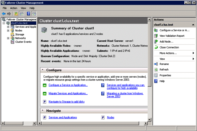
  • In the center pane, find Quorum Configuration, and view the description
  • In the following example, the quorum mode is Node and Disk Majority and the disk witness is Cluster Disk 2.


What is the /admin switch in Microsoft Terminal Services Client (MSTSC) for Windows 2008 and Vista?

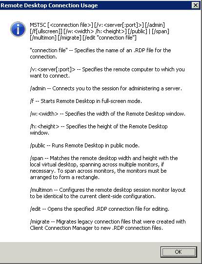
Although the /console switch no longer has any effect on Server 2008 and Vista Terminal Server connections, a new switch called the /admin switch has a similar effect when you use it to connect to a Server 2008 server with the Terminal Services role. When you use this switch with MSTSC, connections don’t consume Terminal Services CALs.

The /admin switch involves elevated rights. If a user has the authority to use the /admin switch but has been marked with Deny Users Permissions To Log On To Terminal Server, he or she will be able to connect using mstsc /admin. Also, if a terminal server is in drain mode (no new sessions are accepted), an /admin session can still be created. The /admin sessions don’t count toward the session limit that may be configured on a terminal server to limit the number of session

Implementing Microsoft Network Load Balancing in a Virtualized Environment

Network Load Balancing is a feature of recent Microsoft server operating systems, including Windows 2000 Advanced Server, Windows Server 2003, and Windows Server 2008. This clustering technology enables you to improve the scalability and availability of Internet server programs, such as Web servers, proxy servers, DNS servers, FTP servers, virtual private network servers, streaming media servers, and terminal services servers.
In addition, it can detect host failures and automatically redistribute traffic to servers that are still operating.
In a VMware® Infrastructure 3 environment, you can create a cluster for Network Load Balancing using virtual machines on the same host or virtual machines on multiple hosts.

Network Load Balancing Basics

Network Load Balancing is implemented in a special driver installed on each Windows host in a cluster. The cluster presents a single IP address to clients. When client requests arrive, they go to all hosts in the cluster, and an algorithm implemented in the driver maps each request to a particular host. The other hosts in the cluster drop the request. You can set load partitioning to distribute specified percentages of client connections to particular hosts. You also have the option of routing all requests from a particular client to the host that handled that client’s first request.
Hosts in the cluster exchange heartbeat messages so they can maintain consistent information about what hosts are members of the cluster. If a host fails, client requests are rebalanced across the remaining hosts, with each remaining host handling a percentage of requests proportional to the percentage you specified in the initial configuration.

Planning a Network Load Balancing Cluster

Network Load Balancing relies on the fact that incoming packets are directed to all cluster hosts and passed to the Network Load Balancing driver for filtering.
You can configure a Network Load Balancing cluster in one of the following modes:

  • Multicast

Multicast mode allows communication among hosts because it adds a Layer 2 multicast
address to the cluster instead of changing the cluster. Communication among hosts is possible because the hosts retain their original unique media access control (MAC) addresses and already have unique, dedicated IP addresses. However, the address resolution protocol (ARP) reply that is sent by a host in the cluster (in response to an ARP request) maps the cluster’s unicast IP address to its multicast MAC address.
Some routers do not support the resolution of unicast IP addresses to multicast MAC addresses, and they discard the ARP reply. As a result, an administrator must add a static ARP entry in the router, mapping the cluster IP address to its MAC address.

NOTE VMware recommends that you use multicast mode, because unicast mode forces the physical switches on the LAN to broadcast all Network Load Balancing traffic to every machine on the LAN.

  • Unicast

Unicast mode works seamlessly with all routers and Layer 2 switches. However, this mode induces switch flooding, a condition in which all switch ports are flooded with NLB Traffic, even ports to which servers which not involved in NLB are attached. To communicate among hosts, you must have a second virtual adapter for each host.
Normally, switched environments avoid port flooding when a switch learns the MAC addresses of the hosts that are sending network traffic through it. The Network Load Balancing cluster masks the cluster’s MAC address for all outgoing traffic to prevent the switch from learning the MAC address.

On an ESX host, the VMkernel sends a reverse address resolution protocol (RARP) packet each time certain actions occur—for example, when a virtual machine is powered on, when there is a teaming failover, or when certain VMotion operations occur. The RARP packet gives physical switches the MAC address of the virtual machine involved in the action. In a Network Load Balancing cluster environment, after a Network Load Balancing node is powered on, the notification in the RARP packet exposes the MAC address of the cluster NIC. As a result, switches might begin to send all inbound traffic destined for the Network Load Balancing cluster through one switch port to a single node of the cluster.

Because the virtual switch operates with complete data about the underlying MAC addresses of the virtual NICs inside each virtual machine, it always correctly forwards packets containing a MAC address matching that of a running virtual machine. As a result of this behavior, the virtual switch does not forward traffic destined for the Network Load Balancing MAC address outside the virtual environment into the physical network, because it is able to forward it to a local virtual machine

Configuring Network Load Balancing in Windows

  1. Install a Windows operating system that supports Network Load Balancing in your virtual machines.
  2. You should install two virtual NICs in each virtual machine that will be part of the Network Load Balancing cluster. One virtual NIC from each virtual machine is used for Network Load Balancing. The other virtual NIC is used for management of the Windows virtual machine.
  3. Each Network Load Balancing node requires a static IP address to be assigned to the Network Load Balancing‐bound adapter. You need one or more additional static IP addresses to be used as the virtual IP addresses of the Network Load Balancing cluster. Use IP addresses that belong to the same subnet.
  4. Configure Network Load Balancing options using one of the following: Network Load Balancing Manager or Network Load Balancing Properties dialog box accessed through Network Connections
  5. VMware recommends that you use the Network Load Balancing Manager.
    Using both Network Load Balancing Manager and Network Connections to change Network Load Balancing properties can lead to unpredictable results.

You can use Network Load Balancing Manager from inside a node or from a remote machine that can communicate with all nodes. By default, Network Load Balancing Manager is installed on Windows Server 2003, and you can access it by clicking Settings > Control Panel > Administrative Tools > Network Load Balancing Manager.

Configuring Multicast Mode on VMware Switches

You do not need to take any special steps to configure your ESX host when you are using multicast mode.

Configuring Unicast Mode VMware Switches

This procedure helps prevent RARP packet transmission for the virtual switch as a whole. This setting affects all the port groups that use the switch. To prevent RARP Packet Transmission for a Virtual Switch, do the following

  1. Log on to the VI Client and select the ESX host.
  2. Click the Configuration tab.
  3. Choose Networking and, for the virtual switch, select Properties.
  4. On the Ports tab, select the virtual switch and click Edit.
  5. Click the NIC Teaming tab, set Notify Switches to No.
  6. Click OK and close the vSwitch Properties dialog box

Complete the following steps to prevent RARP packet transmission only for an individual port group. This setting overrides the setting you make for the virtual switch.

  1. Log on to the VI Client and select the ESX host.
  2. Click the Configuration tab.
  3. Choose Networking and, for the virtual switch, select Properties
  4. On the Ports tab, select the port group and click Edit.
  5. Click the NIC Teaming tab, set Notify Switches to No.
  6. Click OK and close the vSwitch Properties dialog box.
  7. Click OK and close the vSwitch Properties dialog box.

What happens to the Packets?

  • The packets/connections simply reach the network adaptor of each machine in the cluster
  • The NLB module sits right on top of the adaptor driver and receives the packet
  • Based on the source ip address of the client and/OR the port number of the client, an algorithm in the NLB module of each server in the cluster decides whether they should pickup this connection or not
  • The algorithm guarantees that only one machine in the cluster will pick up the packet. Think of this as an agree-upon horizontal partitioning strategy. For instance a trivial implementation could be, that in a two machine cluster – machine 1 picks up all connections with odd ip addresses and machine 2 picks up all connections with even IP addresses. This strategy is fool proof and does not require any communication between the machines at all. The actual algorithm is a randomization algorithm that uses more than just the client ip address (based on configuration) to determine whether it should pick up that packet
  • If the NLB module figures that this packet should be picked up by it, it simply passes it through the stack upwards. If not it simply discards the packet at this stage itself
  • NLB supports differential load balancing configurations wherein one can specify unequal distribution of load between machines in a cluster and its algorithm will automatically take care of it
  • NLB also maintains a heartbeat between machines and if any machine is found to be down, it will automatically redistribute the load amongst the remaining machines
  • NLB also supports client_affinity (another name for sticky sessions) where in connections originating from a single IP will be sent to a single source. This can screw up if one is using a reverse-proxy in front of the cluster, since all connections will appear to originate from a single ip address. One should not enable client_affinity if one has a reverse proxy. In most cases if you have a reverse-proxy, the reverse-proxy itself can perform relevant load balancing, so NLB would be redundant

As new machines join or are removed from the cluster, in order for the load to be distributed correctly among all active nodes, the algorithm must be re-executed in an extremely important re-evaluation process called convergence. It is also important to realize that at no time is NLB ever aware of what the load is on any particular cluster node because NLB cannot determine whether a node’s CPU usage is extremely high or that a node has little to no available memory to process a request

Advantages of NLB

  • Network Load Balancing is very efficient and can provide a very big performance improvement for each machine added into the cluster.
  • NLB has a fault tolerance capability. Many other load balancing implementations, such as Round Robin DNS (RRDNS), continue to send requests to servers that have “died” until system administrators pick up on the fact that there is a problem and then manually perform a configuration change. The key is redundancy in addition to load balancing; if any machine in the cluster goes down, NLB will re-balance the incoming requests to the still running servers thus handling scenarios where a power supply has burnt out, a network card has gone bad, the primary hard disk has crashed, etc
  • This level of redundancy increasing the load balancing capability becomes simply a matter of adding machines to the cluster, which results in a practically unlimited application scalability.
  • NLB works with any TCP or UDP application-based protocol. This means that it’s possible to configure a variety of NLB clusters within an organization, and each one can have its own specific function. For example, one cluster may be dedicated to handling all Internet-originated HTTP traffic while another may be used to serve all intranet requests. If the employees have a need for transferring files, there can be a FTP cluster acting as centralized file storage with closely monitored uploads and downloads
  • By far, one of the biggest advantages of NLB is its ease of use. NLB installs only a networking driver component – absolutely no special hardware is required. Not only does this facilitate the deployment of a load balancing solution, but it also significantly reduces costs

References

  • “Checklist: Enabling and configuring Network Load Balancing”

http://go.microsoft.com/fwlink/?LinkId=18371

  • Reasons for using NLB

http://technet2.microsoft.com/windowsserver/en/library/7698646d‐510e‐47f9‐9b09‐b31dec12be3a1033.mspx

What is Kerberos and how does it work?

I couldn’t have written it better myself so here’s a link to a blog on Kerberos and IIS and cross domain trusts.

http://adopenstatic.com/faq/

How Kerberos Works

The current version of Kerberos is v5, which was developed in 1993. This is the version on which Microsoft’s implementation in Windows 2000/XP/Server 2003 is based. Windows 2000 and Server 2003 native mode domains use Kerberos by default. Domains that must authenticate NT systems along with the newer operating systems must use NT LAN Manager (NTLM) authentication.

Kerberos was named after Cerberus, the three-headed dog of Greek mythology, because of its three components


  • A Key Distribution Center (KDC), which is a server that has two components: an Authentication Server and a Ticket Granting Service.
  • The client (user)
  • The server that the client wants to access

Logon process works with Kerberos as the authentication method

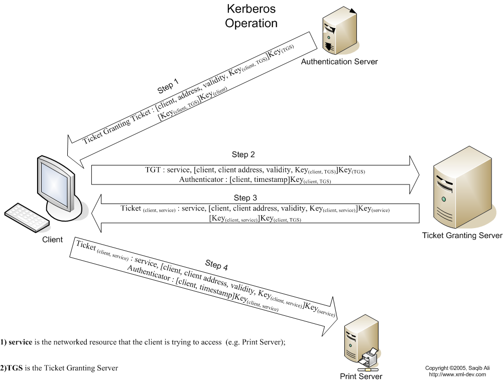
  1. To log on to the network, the user provides an account name and password.
  2. The Authentication Server (AS) component of the KDC accesses Active Directory user account information to verify the credentials.
  3. The KDC grants a Ticket Getting Ticket (TGT) that allows the user to get session tickets to access servers in the domain, without having to enter the credentials again (the TGT is good for 10 hours by default; this expiration period can be configured by the administrator).
  4. When the user attempts to access resources on a server in the domain, the TGT is used to make the request. The client presents the TGT to the KDC to obtain a service ticket.
  5. The Ticket Granting Service (TGS) component of the KDC authenticates the TGT and then grants a service ticket. The service ticket consists of a ticket and a session key. A service ticket is created for the client and the server that the client wants to access.
  6. The client presents the service ticket to create a session with the service on the server. The server uses its key to decrypt the information from the TGS, and the client is authenticated to the server.
  7. If mutual authentication is enabled, the server also authenticates to the client

NTFS Permissions after copying or moving Files

Useful for Reference.

Copying Files and Folders

When copying folder or files from one folder to another folder or from one partition to another partition, permissions for this files or folders may change.

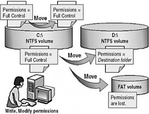
  1. When copying a folder or file within same NTFS partition, the copy of the folder or file inherits the destination folder permissions
  2. When copying a folder or file between different NTFS partitions, the copy of the folder or file inherits the destination folder permissions.
  3. When copying folders or files to non NTFS partitions such as File Allocation table (FAT), the files or folders will lose their all NTFS permissions.

Moving Files and Folders

When moving a file or a folder, permissions may get changed depending on the destination folder permissions.

Note: To move folders and files within an NTFS partitions you must have both permissions, for the destination folder you should have write permission and modify permissions for source file or folder to configure the options. You need to have modified permission for folder or file to move as Windows 2000 will remove the file or folder from the main folder after copying it to the folder destination.

  1. When moving a file to a folder within the same NTFS partition, the folder or file will retains its original permissions.
  2. When moving a folder or file between different NTFS partitions, the file or folder will inherit the destination folder permissions.
  3. When moving files to folders on NTFS partitions to non NTFS partitions the folders and files will lose their all NTFS permissions, as NTFS permissions are not supported by non NTFS partitions.

ICACLS Permissions

In my last role, we had to create large folder structures including permissioning very quickly in Windows 2008 R2 and as a result we came across ICALCS which proved very useful .

ICACLS name /save aclfile [/T] [/C]

Store the acls for all matching file/folder names into aclfile for later use with /restore.

ICACLS directory [/substitute SidOld SidNew […]] /restore aclfile [/C]

Applies the stored acls to files in directory.

ICACLS name /setowner user [/T] [/C]

Changes the owner of all matching names.

ICACLS name /findsid Sid [/T] [/C]

Finds all matching names that contain an ACL explicitly mentioning Sid.

ICACLS name /verify [/T] [/C]

Finds all files whose ACL is not in canonical form or whose lengths are inconsistent with ACE counts.

ICACLS name /resize [/T] [/C] [/L]

Changes incorrect recorded lengths of ACLs to true lengths.

ICACLS name /reset [/T] [/C]

Replaces acls with default inherited acls for all matching files.

ICACLS name [/grant[:r] Sid:perm[…]]

                       [/deny Sid:perm […]]

                       [/remove[:g|:d]] Sid[…]] [/T] [/C]

With :r, the permissions replace any previously granted explicit permissions.

Without :r, the permissions are added to any previously granted explicit permissions.

/deny Sid:perm explicitly denies the specified user access rights.

An explicit deny ACE is added for the stated permissions and the same permissions in any explicit grant are removed.

/remove[:[g|d]] Sid removes all occurrences of Sid in the acl.

With :g, it removes all occurrences of granted rights to that Sid.

With :d, it removes all occurrences of denied rights to that Sid.


Note:

Sids may be in either numeric or friendly name form. If a numeric form is given, affix a * to the start of the SID.

/T indicates that this operation is performed on all matching files/directories below the directories specified in the name.

/C indicates that this operation will continue on all file errors.

Error messages will still be displayed.


ICACLS preserves the canonical ordering of ACE entries:

Explicit denials

Explicit grants

Inherited denials

Inherited grants


Perm is a permission mask and can be specified in one of two forms:

1. A sequence of simple rights:

F – full access

M – modify access

RX – read and execute access

R – read-only access

W – write-only access


2. A comma-separated list in parentheses of specific rights:

D – delete

RC – read control

WDAC – write DAC

WO – write owner

S – synchronize

AS – access system security

MA – maximum allowed

GR – generic read

GW – generic write

GE – generic execute

GA – generic all

RD – read data/list directory

WD – write data/add file

AD – append data/add subdirectory

REA – read extended attributes

WEA – write extended attributes

X – execute/traverse

DC – delete child

RA – read attributes

WA – write attributes


Inheritance rights may precede either form and are applied only to directories:

(OI) – object inherit

(CI) – container inherit

(IO) – inherit only

(NP) – don’t propagate inherit


Examples:

icacls c:\windows\* /save AclFile /T

– Will save the ACLs for all files under c:\windows and its subdirectories to AclFile.

icacls c:\windows\ /restore AclFile

– Will restore the Acls for every file within AclFile that exists in c:\windows and its subdirectories

icacls file /grant Administrator:(D,WDAC)

– Will grant the user Administrator Delete and Write DAC permissions to file

icacls file /grant Administrator:(OI)(CI)M

– Will grant the user Administrator Modify permissions to the file and ripple this downwards for file and folder permissions

icacls file /grant *S-1-1-0:(D,WDAC)

– Will grant the user defined by sid S-1-1-0 Delete and Write DAC permissions to file


Folder Path Spaces

If there are spaces in the folder path names, you will need to put quotes in as follows

ICACLS “C:\Test Folder\Second Part\Third Part” /grant user123:(OI)(CI)R