Archive for microsoft

Group Policy and Microsoft Office Templates on Server 2008 R2

Policy

Managing Group Policy ADMX Files

Microsoft Windows Vista® and Windows Server 2008 introduce a new format for displaying registry-based policy settings. Registry-based policy settings (located under the Administrative Templates category in the Group Policy Object Editor) are defined using a standards-based, XML file format known as ADMX files. These new files replace ADM files, which used their own markup language. The Group Policy tools; Group Policy Object Editor and Group Policy Management Console remain largely unchanged. In the majority of situations, you won’t notice the presence of ADMX files during day-to-day Group Policy administration tasks.

ADMX files provide an XML-based structure for defining the display of the Administrative Template policy settings in the Group Policy tools. The Group Policy tools will recognize ADMX files only if you are using a Windows Vista–based or Windows Server 2008–based computer.

Unlike ADM files, ADMX files are not stored in individual GPOs. For domain-based enterprises, administrators can create a central store location of ADMX files that is accessible by anyone with permission to create or edit GPOs. Group Policy tools will continue to recognize custom ADM files you have in your existing environment, but will ignore any ADM file that has been superseded by ADMX files: System.adm, Inetres.adm, Conf.adm, Wmplayer.adm, and Wuau.adm. Therefore, if you have edited any of the these files to modify existing or create new policy settings, the modified or new settings will not be read or displayed by the Windows Vista–based Group Policy tools.

The Group Policy Object Editor automatically reads and displays Administrative Template policy settings from ADMX files that are stored either locally or in the optional ADMX central store. The Group Policy Object Editor will automatically read and display Administrative Template policy settings from custom ADM files stored in the GPO. You can still add or remove custom ADM files with the Add/Remove template menu option. All Group Policy settings currently in ADM files delivered by the Windows Server 2003, Windows XP, and Windows 2000 will also be available in Windows Vista and Windows Server 2008 ADMX files.

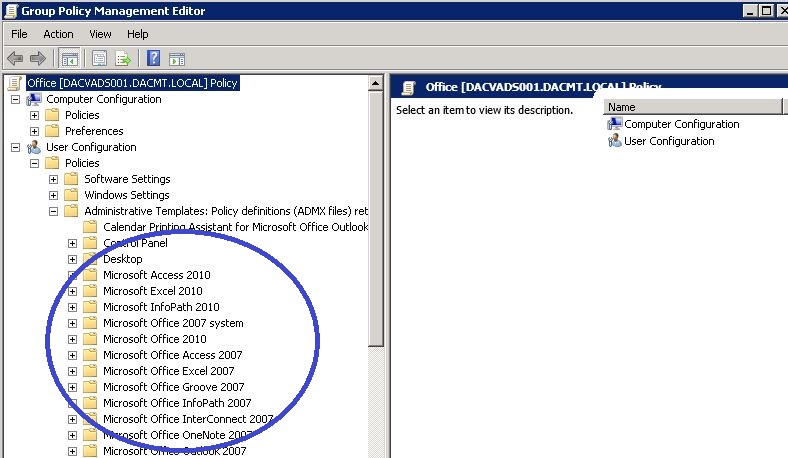
Note: I have tested the Co-Existence of the 2007 Microsoft Office Templates and the 2010 Microsoft Office Templates and they seem to work together nicely. See pic below. The same process applies to adding a second lot of templates

Office2007templates

Procedure

officegpo11

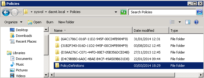
  • The central store is a folder structure created in the Sysvol directory on the domain controllers in each domain in your organization. You will need to create the central store only once on a single domain controller for each domain in your organization. The File Replication service then replicates the central store to all domain controllers in a domain. However, it is recommended that you create the central store on the primary domain controller. Group Policy Management Console and Group Policy Object Editor can use ADMX files more quickly because Group Policy tools connect to the primary domain controller by default.
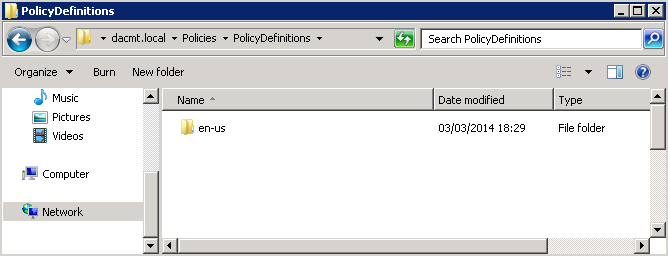
  • Create a subfolder of \\dacmt.local\sysvol\domain\Policies\PolicyDefinitions\en-us for each language your Group Policy administrators will use. Each subfolder is named after the appropriate ISO-style Language/Culture Name. E.g %domain%\sysvol\domain\policies\PolicyDefinitions\en-us

officegpo12

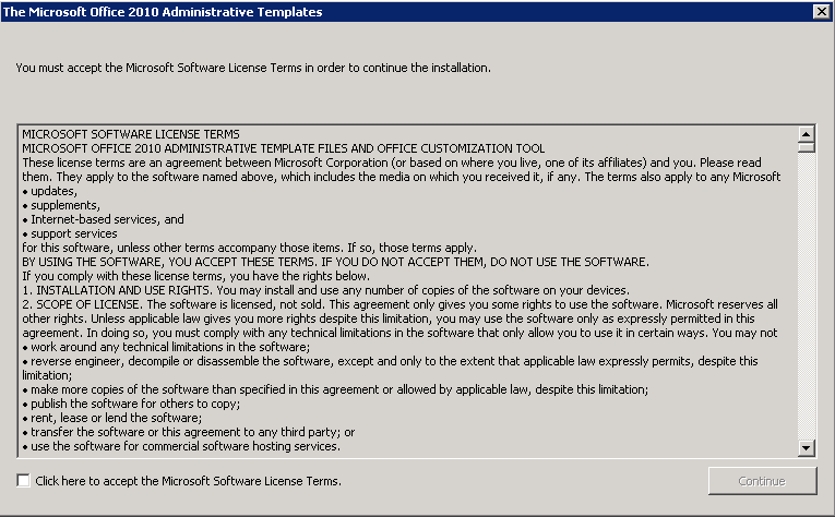
  • Run the Office 2010 Administrative Template exe as per below and save the 3 folders into a temp folder

officegpo1

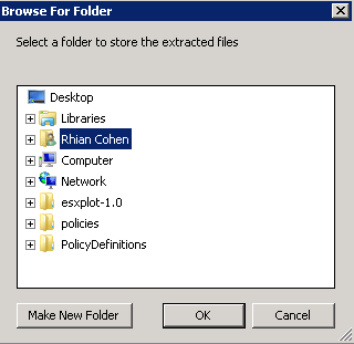
  • Save into a temp folder for now

officegpo2

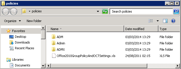
  • You should now see the following 3 folders

officegpo3

  • Go to your downloaded Office 2010 files and copy the admx files into the %domain%\sysvol\domain\policies\PolicyDefinitions folder
  • Go to your downloaded files and copy the adml files into the %domain%\sysvol\domain\policies\PolicyDefinitions\EN-US Folder
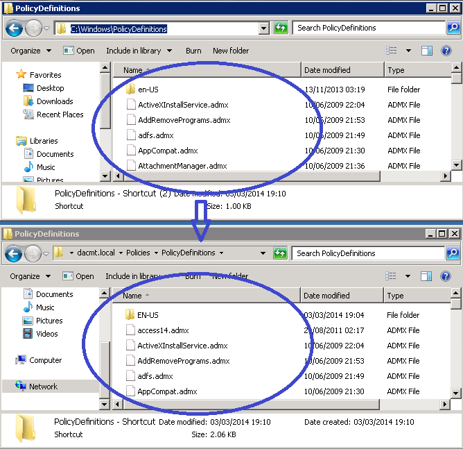
  • You now need to go to c:\Windows\Policy Definitions and copy what is in here into the \\dacmt.local\sysvol\domain\Policies\PolicyDefinitions\ folder and the \\dacmt.local\sysvol\domain\Policies\PolicyDefinitions\en-us folder as this will allow you to see the existing Administrative Templates along with the new Office ones

officegpo13

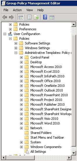
  • Open Group Policy Management console and you should now see the following

officegpo14

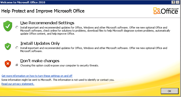
If you then navigate into each Office Setting. For example, go into Microsoft Office, you can suppress the initial box which pops up saying Welcome to Microsoft Office etc

officegpo10

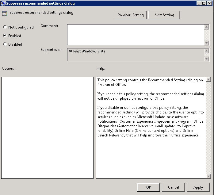
  • And this is the Group Policy below which will stop the above screen

officegpo9

  • Now you can go through any which you need to apply
  • Voila 🙂

Useful Links

http://technet.microsoft.com/en-us/library/cc748955%28v=ws.10%29.aspx

http://technet.microsoft.com/en-us/library/gg490629%28v=office.14%29.aspx

Understanding Active Directory Domain Services (AD DS) Functional Levels

level

What are Functional Levels?

Functional levels determine the available Active Directory Domain Services (AD DS) domain or forest capabilities. They also determine which Windows Server operating systems you can run on domain controllers in the domain or forest. However, functional levels do not affect which operating systems you can run on workstations and member servers that are joined to the domain or forest.

When you deploy AD DS, you need to set the domain and forest functional levels to the highest value that your environment can support. This way, you can use as many AD DS features as possible. For example, if you are sure that you will never add domain controllers that run Windows Server 2003 to the domain or forest, select the Windows Server 2008 functional level during the deployment process. However, if you might retain or add domain controllers that run Windows Server 2003, select the Windows Server 2003 functional level.

When you deploy a new forest, you are prompted to set the forest functional level and then set the domain functional level. You cannot set the domain functional level to a value that is lower than the forest functional level. For example, if you set the forest functional level to Windows Server 2008, you can set the domain functional level only to Windows Server 2008. In this case, the Windows 2000 native and Windows Server 2003 domain functional level values are not available. In addition, all domains that you subsequently add to that forest have the Windows Server 2008 domain functional level by default.

You can set the domain functional level to a value that is higher than the forest functional level. For example, if the forest functional level is Windows Server 2003, you can set the domain functional level to Windows Server 2003or higher.

Guidelines for raising domain and forest functional levels

  • You must be a member of the Domain Admins group to raise the domain functional level.
  • You must be a member of the Enterprise Admins group to raise the forest functional level.
  • You can raise the domain functional level on the primary domain controller (PDC) emulator operations master only. The AD DS administrative tools that you use to raise the domain functional level (the Active Directory Domains and Trusts snap-in and the Active Directory Users and Computers snap-in) automatically target the PDC emulator when you raise the domain functional level.
  • You can raise the forest functional level on the schema operations master only. Active Directory Domains and Trusts automatically targets the schema operations master when you raise the forest functional level.
  • You can raise the functional level of a domain only if all domain controllers in the domain run the version or versions of Windows Server that the new functional level supports.
  • You can raise the functional level of a forest only if all domain controllers in the forest run the version or versions of Windows Server that the new functional level supports.
  • You cannot set the domain functional level to a value that is lower than the forest functional level, but you can set it to a value that is equal to or higher than the forest functional level.
  • With versions of Windows Server that are earlier than Windows Server 2008 R2, you cannot roll back or lower a functional level under any circumstances. If you have to revert to a lower functional level with a version of Windows Server that is earlier than Windows Server 2008 R2, you must rebuild the domain or forest or restore it from a backup copy.
  • After you set the domain functional level, you cannot roll back or lower the domain functional level except in the cases listed in the following table. The domain functional level can be lowered only by using Windows PowerShell
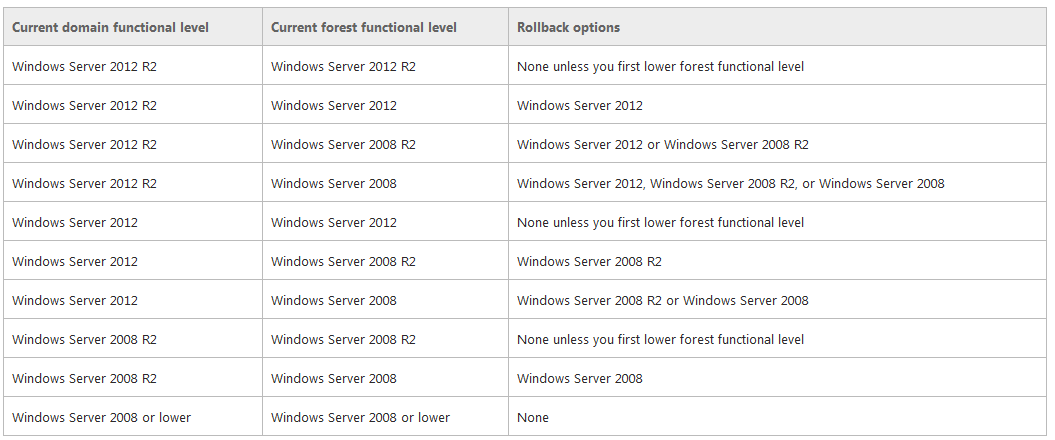
Rollback

  • Make sure replication is working properly

Checking Replication

  • repadmin /replsum

replication1

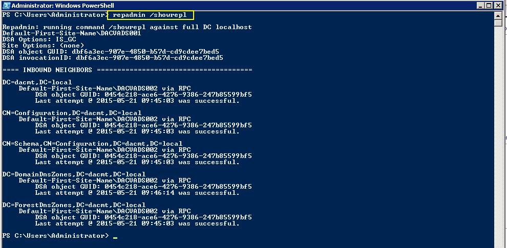
  • repadmin /showrepl

replication2

  • repadmin /bridgeheads

replication3

  • dcdiag /v (checking overall health of the domain)
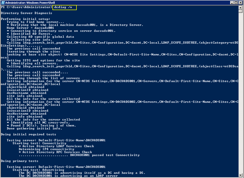
replication4

Checking what Domain Controllers and FSMO roles you have

fsmo

Features available at Forest Function Levels

Windows 2003

  • Domain rename
  • Linked-value replication. Linked-value replication makes it possible for you to change group membership to store and replicate values for individual members instead of replicating the entire membership as a single unit. Storing and replicating the values of individual members uses less network bandwidth and fewer processor cycles during replication, and prevents you from losing updates when you add or remove multiple members concurrently at different domain controllers.
  • The ability to deploy a read-only domain controller (RODC)
  • Improved Knowledge Consistency Checker (KCC) algorithms and scalability. The intersite topology generator (ISTG) uses improved algorithms that scale to support forests with a greater number of sites than AD DS can support at the Windows 2000 forest functional level. The improved ISTG election algorithm is a less-intrusive mechanism for choosing the ISTG at the Windows 2000 forest functional level.
  • The ability to create instances of the dynamic auxiliary class named dynamicObject in a domain directory partition
  • The ability to convert an inetOrgPerson object instance into a User object instance, and to complete the conversion in the opposite direction
  • The ability to create instances of new group types to support role-based authorization.
    These types are called application basic groups and LDAP query groups.
  • Deactivation and redefinition of attributes and classes in the schema. The following attributes can be reused: ldapDisplayName, schemaIdGuid, OID, and mapiID.
  • Domain-based DFS namespaces running in Windows Server 2008 Mode, which includes support for access-based enumeration and increased scalability.

Windows 2008

All of the features that are available at the Windows Server 2003 forest functional level, but no additional features are available. All domains that are subsequently added to the forest, however, operate at the Windows Server 2008 domain functional level by default.

Windows 2008 R2

  • All of the features that are available at the Windows Server 2003 forest functional level, plus the following features:
  • Active Directory Recycle Bin, which provides the ability to restore deleted objects in their entirety while AD DS is running.
  • All domains that are subsequently added to the forest will operate at the Windows Server 2008 R2 domain functional level by default.
  • If you plan to include only domain controllers that run Windows Server 2008 R2 in the entire forest, you might choose this forest functional level for administrative convenience. If you do, you will never have to raise the domain functional level for each domain that you create in the forest.

Windows 2012

  • All of the features that are available at the Windows Server 2008 R2 forest functional level, but no additional features.
  • All domains that are subsequently added to the forest will operate at the Windows Server 2012 domain functional level by default

Windows 2012 R2

  • All of the features that are available at the Windows Server 2008 R2 forest functional level, but no additional features.
  • All domains that are subsequently added to the forest will operate at the Windows Server 2012 domain functional level by default

Features available at Domain Function Levels

Windows Server 2003

  • Universal groups for both distribution and security groups.
  • Group nesting
  • Group conversion, which allows conversion between security and distribution groups
  • Security identifier (SID) history
  • The domain management tool, Netdom.exe, which makes it possible for you to rename domain controllers
  • Logon time stamp updates
    The lastLogonTimestamp attribute is updated with the last logon time of the user or computer. This attribute is replicated within the domain.
  • The ability to set the userPassword attribute as the effective password on inetOrgPerson and user objects
  • The ability to redirect Users and Computers containers
    By default, two well-known containers are provided for housing computer and user accounts, namely, cn=Computers,<domain root> and cn=Users,<domain root>. This feature allows the definition of a new, well-known location for these accounts.
  • The ability for Authorization Manager to store its authorization policies in AD DS
  • Constrained delegation
    Constrained delegation makes it possible for applications to take advantage of the secure delegation of user credentials by means of Kerberos-based authentication.
    You can restrict delegation to specific destination services only.
  • Selective authentication
    Selective authentication makes it is possible for you to specify the users and groups from a trusted forest who are allowed to authenticate to resource servers in a trusting forest

Windows Server 2008

  • All of the default AD DS features, all of the features from the Windows Server 2003 domain functional level, and the following features are available:
  • Distributed File System (DFS) replication support for the Windows Server 2003 System Volume (SYSVOL)
    DFS replication support provides more robust and detailed replication of SYSVOL contents.
  • Beginning with Windows Server 2012 R2, File Replication Service (FRS) is deprecated. A new domain that is created on a domain controller that runs at least Windows Server 2012 R2 must be set to the Windows Server 2008 domain functional level or higher
  • Domain-based DFS namespaces running in Windows Server 2008 Mode, which includes support for access-based enumeration and increased scalability. Domain-based namespaces in Windows Server 2008 mode also require the forest to use the Windows Server 2003 forest functional level.
  • Advanced Encryption Standard (AES 128 and AES 256) support for the Kerberos protocol. In order for TGTs to be issued using AES, the domain functional level must be Windows Server 2008 or higher and the domain password needs to be changed.
  • Last Interactive Logon Information
  • Fine-grained password policies make it possible for you to specify password and account lockout policies for users and global security groups in a domain
  • Personal Virtual Desktops

Windows Server 2008 R2

  • All default Active Directory features, all features from the Windows Server 2008 domain functional level, plus the following features:
  • Authentication mechanism assurance, which packages information about the type of logon method (smart card or user name/password) that is used to authenticate domain users inside each user’s Kerberos token. When this feature is enabled in a network environment that has deployed a federated identity management infrastructure, such as Active Directory Federation Services (AD FS), the information in the token can then be extracted whenever a user attempts to access any claims-aware application that has been developed to determine authorization based on a user’s logon method.
  • Automatic SPN management for services running on a particular computer under the context of a Managed Service Account when the name or DNS host name of the machine account changes

Windows Server 2012

  • The KDC support for claims, compound authentication, and Kerberos armoring KDC administrative template policy has two settings (Always provide claims and Fail unarmored authentication requests) that require Windows Server 2012 domain functional level.

Windows Server 2012 R2

  • DC-side protections for Protected Users. Protected Users authenticating to a Windows Server 2012 R2 domain can no longer: Authenticate with NTLM authentication, Use DES or RC4 cipher suites in Kerberos pre-authentication, Be delegated with unconstrained or constrained delegation, Renew user tickets (TGTs) beyond the initial 4 hour lifetime
  • Authentication Policies: New forest-based Active Directory policies which can be applied to accounts in Windows Server 2012 R2 domains to control which hosts an account can sign-on from and apply access control conditions for authentication to services running as an account.
  • Authentication Policy Silos: New forest-based Active Directory object, which can create a relationship between user, managed service and computer, accounts to be used to classify accounts for authentication policies or for authentication isolation.

NTDSUTIL

This tool can remove old AD DC metadata which can stop the raising of Functional Levels

https://technet.microsoft.com/en-us/library/cc728068%28WS.10%29.aspx
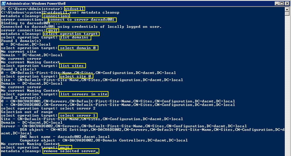
ntdsutil

The GUI Metadata Cleanup Utility

The GUI Metadata Cleanup Utility removes Active Directory domain controller metadata left behind after a domain controller is removed improperly or unsuccessfully

https://gallery.technet.microsoft.com/scriptcenter/d31f091f-2642-4ede-9f97-0e1cc4d577f3

Forest Recovery Information

https://technet.microsoft.com/en-us/library/8e3e4377-ef54-4a70-9215-a5d2ba4d0eb9%28v=ws.10%29#BKMK_ResetTrustPassword

http://blogs.technet.com/b/askds/archive/2011/06/14/what-is-the-impact-of-upgrading-the-domain-or-forest-functional-level.aspx

Useful Microsoft Link

https://technet.microsoft.com/library/understanding-active-directory-functional-levels%28WS.10%29.aspx

Questions?

  • Once you have upgraded the Domain functional level, how long should you wait before upgrading the forest functional level?

The change should take effect immediately as soon as the operation completes on the server. if you have multiple DC’s or domain, it may take longer. If you have plenty of time and want to play it safe, wait 24 hours but normally 15 minutes is fine. if you have multiple DC’s, you can log into each DC and verify the functional level.

  • By raising the root domain functional level, will this automatically raise any child domains or do we need to raise the level on the PDC of the root domain then raise the level on the PDC in the child domain? Or do we do the child first then the root domain?

Each individual domain PDCe is responsible for maintaining it’s domain functional level.  Because of this, where you raise the domain functional level first, does not matter (parent domain or child domain).  Each domain’s DC’s will operate at the domain functional level of it’s PDCe (so long as it is supported).  The Forest Functional Level affects all domains.  As such all domains must be operating at or above the proposed Forest Functional Level.

  • What is the best way to recover if things don’t go to plan? For e.g With a root domain with 2 DCs and a child domain with 5 DCs?

Before Windows Server 2008 R2, the only ways to recover are rebuild or restore from backup.

As the PDCe is responsible for the Domain Functional Level and the Schema Operations Master is responsible for the Forest Functional Level, first, you would have to restore the server that holds the Schema Operations Master in the Parent domain (if you will be reverting to a Domain Functional Level less than allowed by the Forest Functional Level). Then you would restore the server that holds the PDCe FSMO role for each child domain.

  • If we are running at Windows 2000 native domain level with all Windows 2008 R2 servers, can we raise the domain functional level straight to Windows Server 2008 R2?

If all of your DC’s are running Windows Server 2008 R2 then yes.

Microsoft RemoteApp on Windows Server 2012

RemoteApp

Happy New Year and Welcome to the first blog of 2014!

What is RemoteApp?

RemoteApp enables you to make programs that are accessed remotely through Remote Desktop Services appear as if they are running on the end user’s local computer. These programs are referred to as RemoteApp programs. Instead of being presented to the user in the desktop of the Remote Desktop Session Host (RD Session Host) server, the RemoteApp program is integrated with the client’s desktop. The RemoteApp program runs in its own resizable window, can be dragged between multiple monitors, and has its own entry in the taskbar. If a user is running more than one RemoteApp program on the same RD Session Host server, the RemoteApp program will share the same Remote Desktop Services session.

Users can access RemoteApp programs several ways. They can:

  1. Access a link to the program through RemoteApp and Desktop Connection by using Remote Desktop Web Access (RD Web Access).
  2. Double-click a Remote Desktop Protocol (.rdp) file that has been created and distributed by their administrator.
  3. Double-click a program icon on their desktop or Start menu that has been created and distributed by their administrator with a Windows Installer (.msi) package.
  4. Double-click a file where the file name extension is associated with a RemoteApp program. This can be configured by their administrator with a Windows Installer package.

Why use RemoteApp?

RemoteApp can reduce complexity and reduce administrative overhead in many situations, including the following:

  • Branch offices, where there may be limited local IT support and limited network bandwidth.
  • Situations where users need to access programs remotely.
  • Deployment of line-of-business (LOB) programs, especially custom LOB programs.
  • Environments, such as “hot desk” or “hoteling” workspaces, where users do not have assigned computers.
  • Deployment of multiple versions of a program, particularly if installing multiple versions locally would cause conflicts

Instructions for Configuring a RD Session Host Server to Host RemoteApp Programs

First Install the RD Session Host Role Service on your server. RemoteApp Manager is installed as part of the Remote Desktop Session Host (RD Session Host) role service.

  • On the computer on which you want to install the RD Session Host role service, open Server Manager. To open Server Manager, click Start, point to Administrative Tools, and then click Server Manager
  • Under Roles Summary, click Add Roles.
  • On the Before You Begin page of the Add Roles Wizard, click Next

Remoteapp1

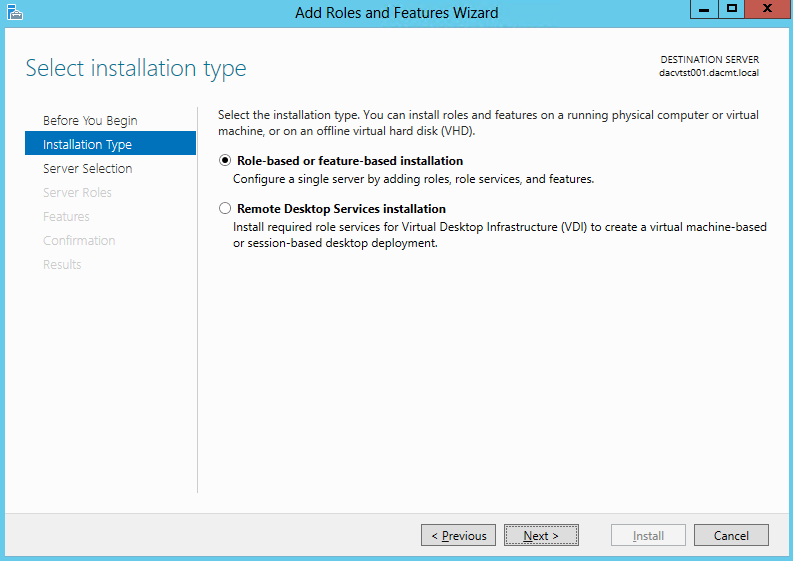
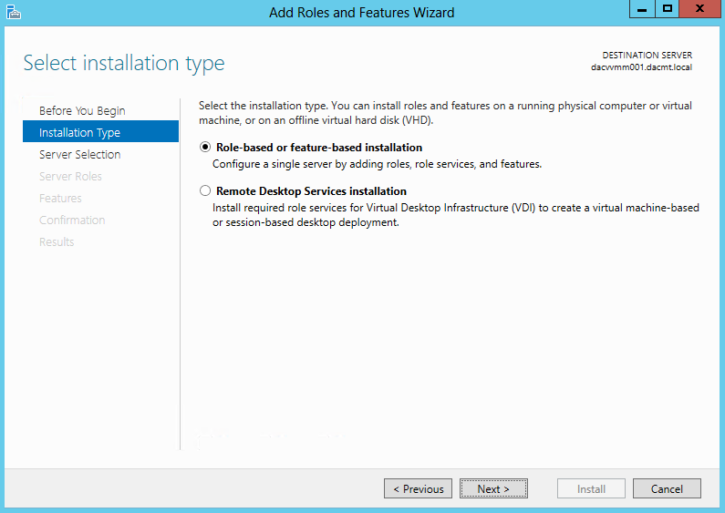
  • On the Select Server Roles page, select the Role based or Feature based installation

Remoteapp0

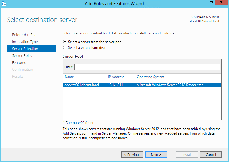
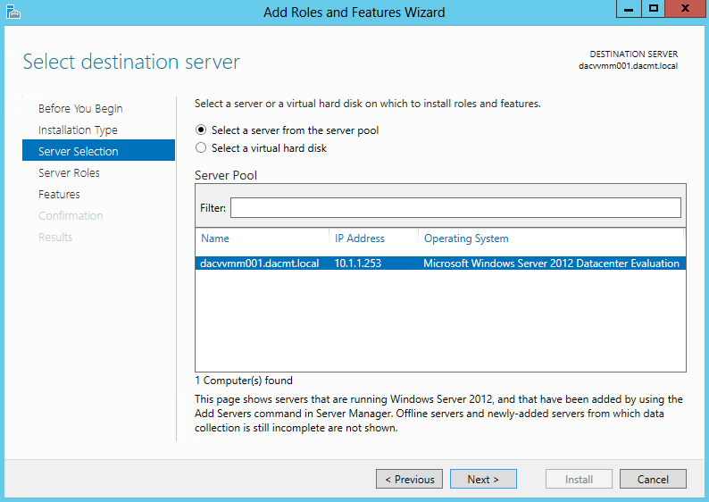
  • Check your Server is selected and click Next

Remoteapp01

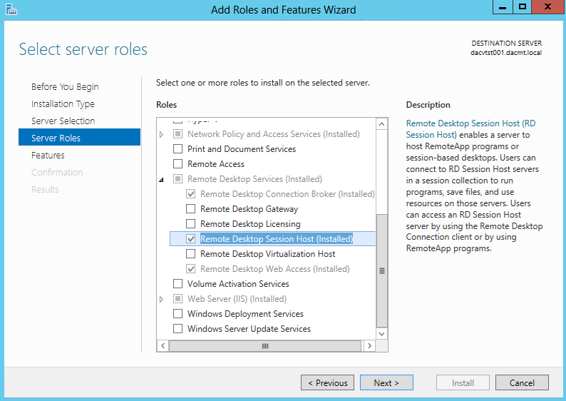
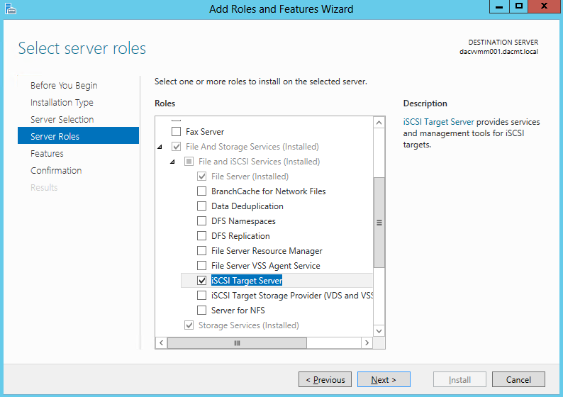
  • On Select Server Roles. select Remote Desktop Session Host. Note: Mine is already installed previously. This is just to show you the wizard
Remoteapp02

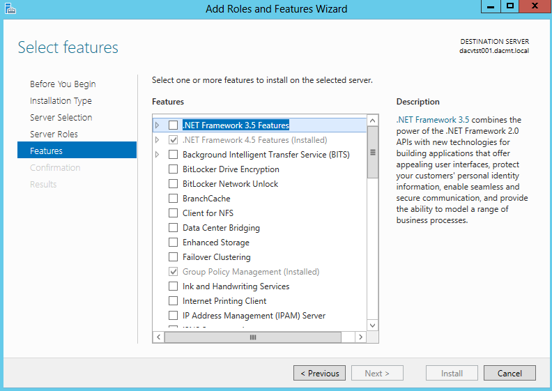
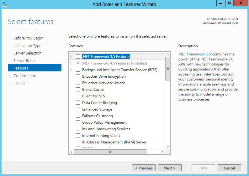
  • Click Next on Select Features

Remoteapp03

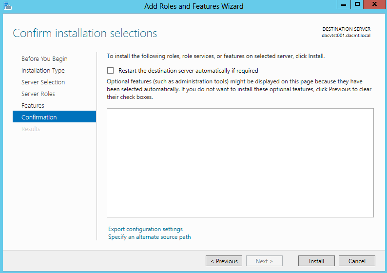
  • Confirm and Install

Remoteapp04

  • Once complete, Open Server Manager. To open Server Manager, click Start, point to Administrative Tools, and then click Server Manager
  • Under Roles Summary, click Add Roles.
  • On the Before You Begin page of the Add Roles Wizard, click Next

Remoteapp1

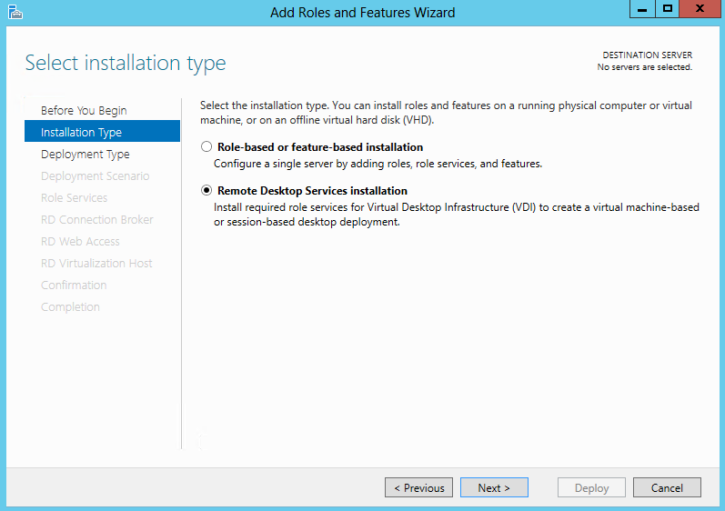
  • Select Remote Desktop Services Installation on the Select Installation Type Page

Remoteapp2

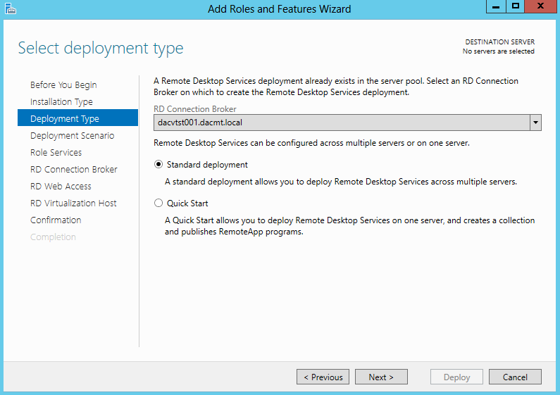
  • Select Standard Deployment on the Select Deployment Type page
  • Standard Deployment: Allows you to flexibly deploy the various Remote Desktop Services role services to different servers.
  • Quick Start: Installs all the necessary Remote Desktop Services’ role services on one computer to let you install and configure in a test environment.
Remoteapp3

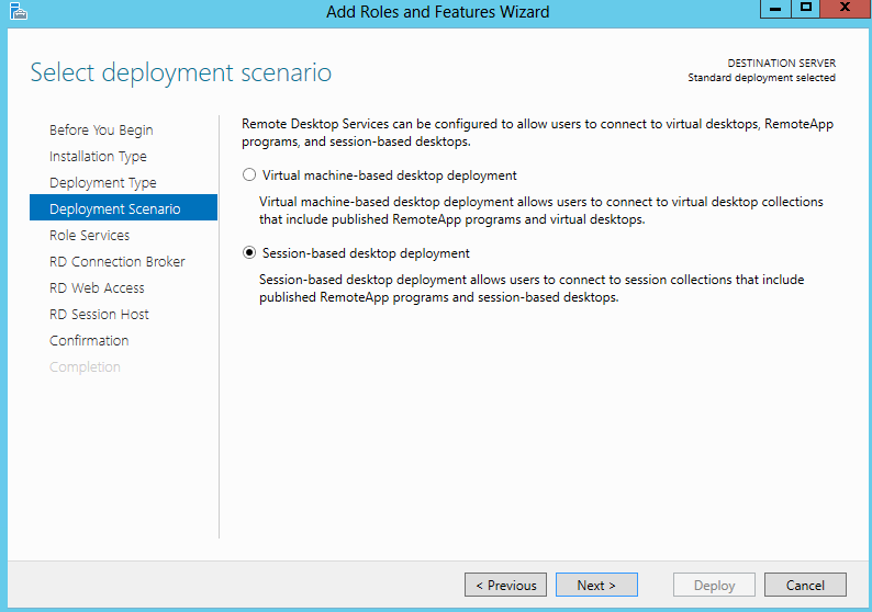
  • On the Deployment Scenario Page, select Session based desktop deployment

Remoteapp4

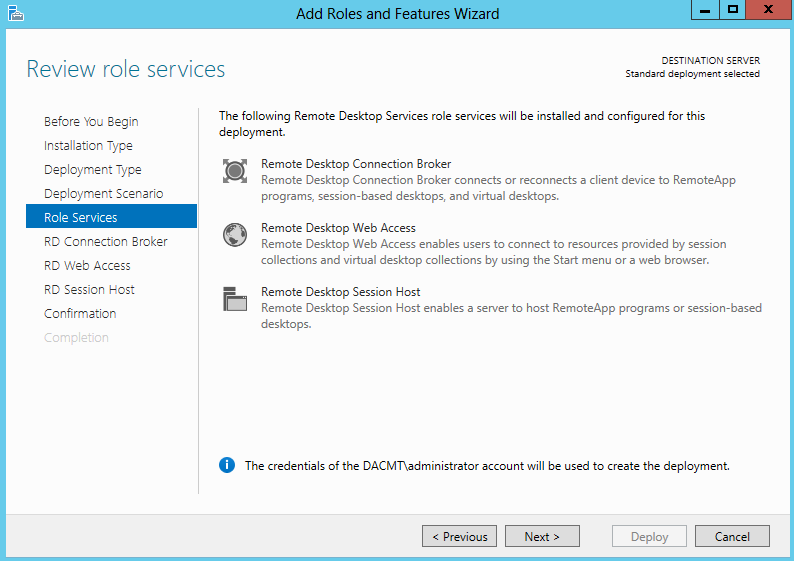
  •  Review Role Services

Remoteapp5

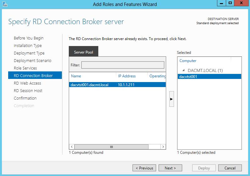
  • Specify the RD Connection Broker Server

Remoteapp6

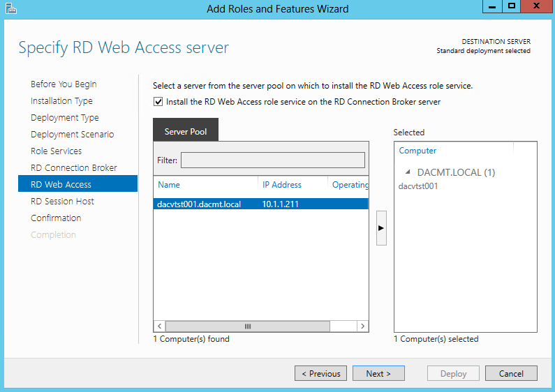
  • Specify RD Web Access Server

Remoteapp7

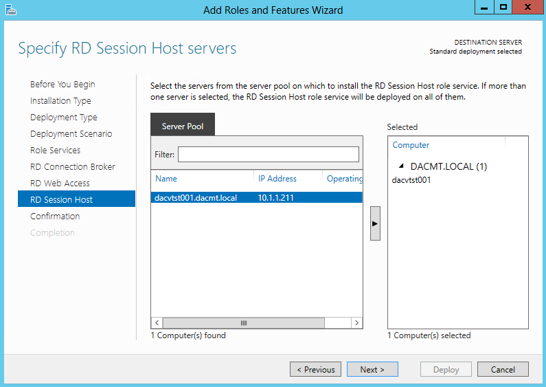
  • Specify RD Session Host Servers

Remoteapp8

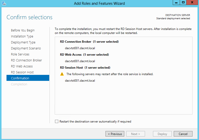
  • Confirm Selections

Remoteapp9

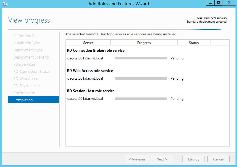
  • View Progress and Computer/VM may restart

Remoteapp10

  • Open Server Manager
  • Click on Remote Desktop Services
  • Click on Create a Session Collection
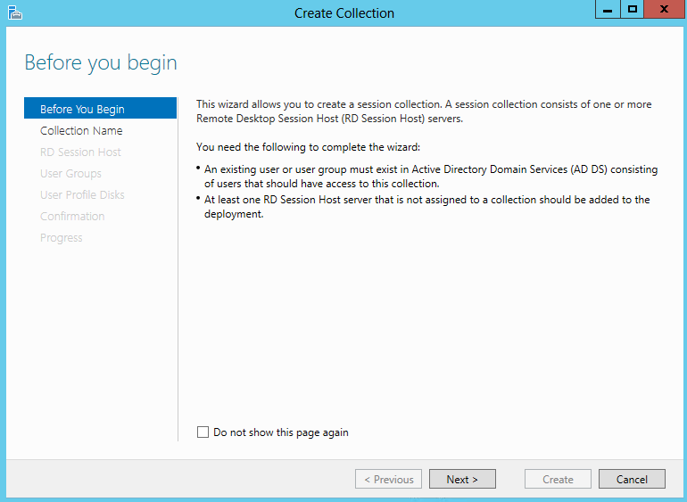
  • On the Before you begin page, click Next

Remoteapp11

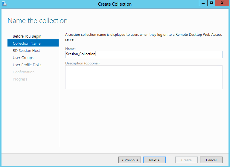
  • Name your Session Collection

Remoteapp12

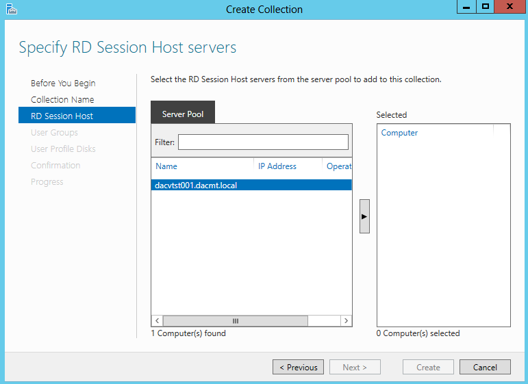
  • Specify RD Session Host Servers. Click the arrow to add the server into the Selected box

Remoteapp13

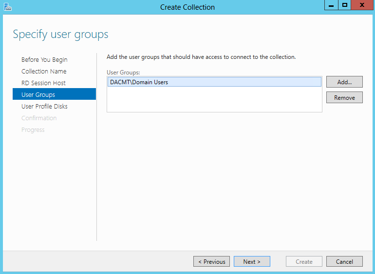
  • Add the User Groups which will have access to the collection

Remoteapp12 Remoteapp14

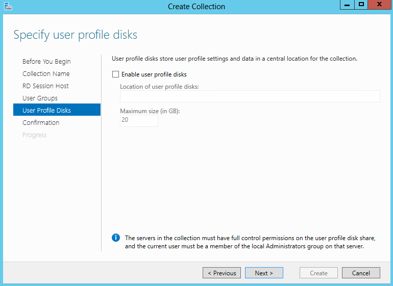
  • On the Specify user profile disks page, clear the Enable user profile disks check box, and then click Next.

Remoteapp15

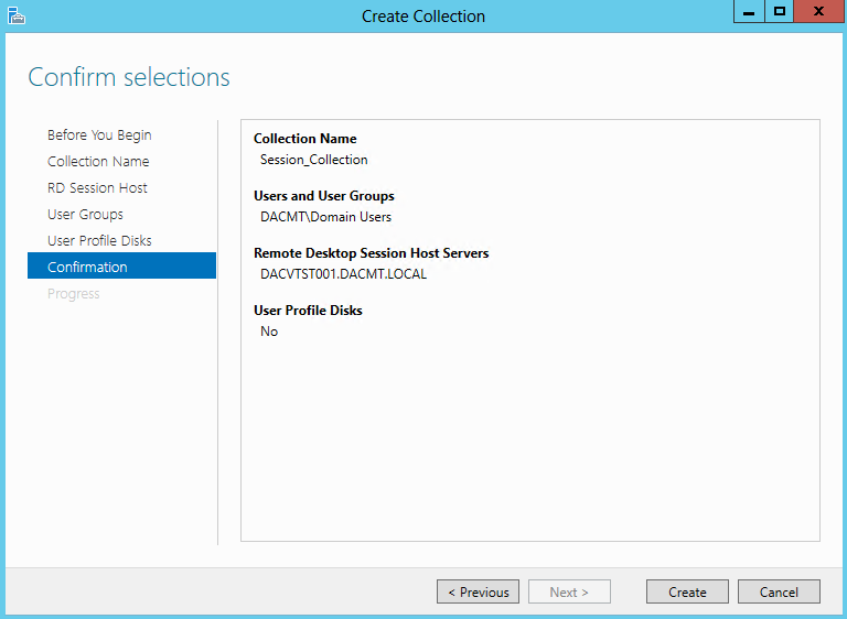
  • Confirm Selections and click Create

Remoteapp16

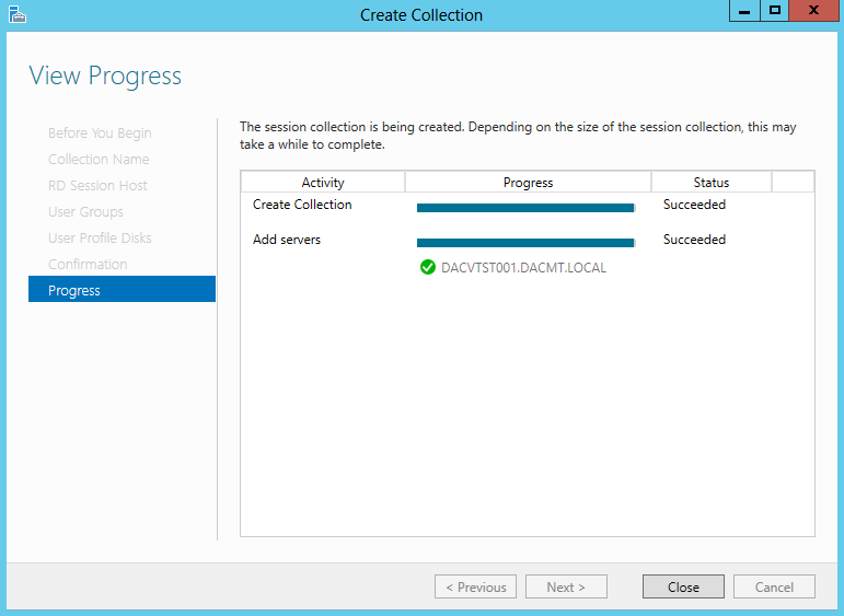
  • Check everything finished ok and click Close

Remoteapp17

  • You can now ensure Session Virtualization standard deployment deployed successfully by connecting to the session collection that was created.
  • If you plan on connecting to an RD Web Access server website from a server, you must turn off Internet Explorer Enhanced Security Configuration by using Server Manager.
  • To test that the Session Virtualization standard deployment deployed and the session collection was created successfully, you log on to the RD Web Access server on the RDWA1 computer and connect to a session in the SessionCollection session collection
  • In the Internet Explorer address bar, type https://dacvtst001.dacmt.local/RDWeb and then press Enter.

Remoteapp18

  • Click Continue to this website (not recommended
  • It may come up with a prompt to install an add-on called Microsoft Remote Desktop Services Web Access Connection

Remoteapp19

  • In the Domain/user name box, type Domain\Administrator. In my case DACMT\Administrator

Remoteapp20

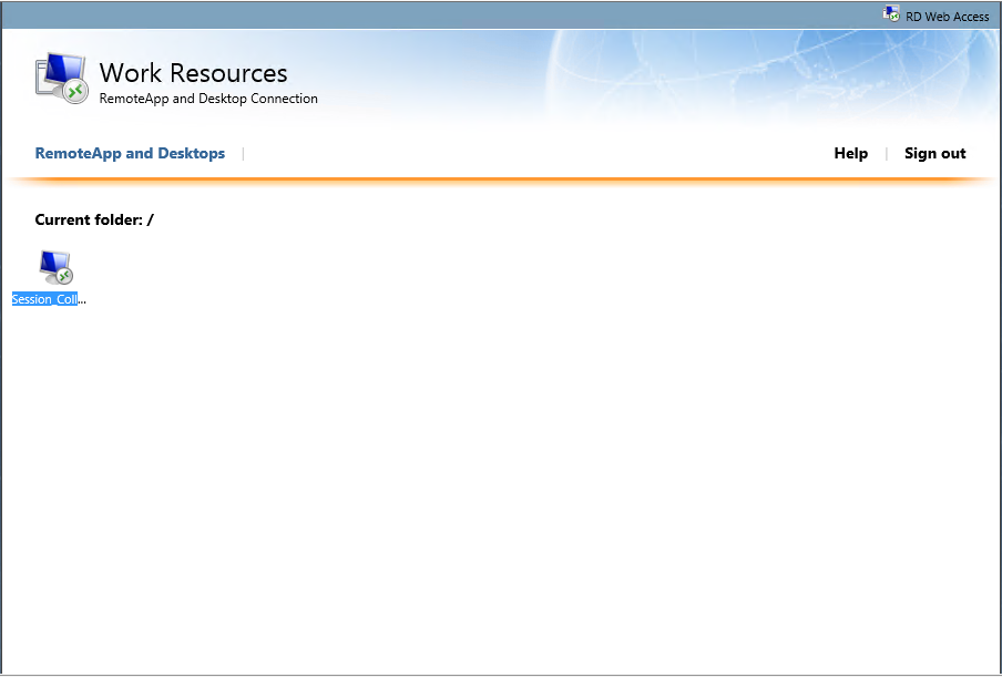
  • You should now see your Session Collection

Remoteapp21

  • Click SessionCollection, and then click Connect. Click Open if you get the message below

Remoteapp22

  •  Verify that the session-based desktop appears correctly.
  • Next we need to publish a Remote App Program
  • Open Server Manager
  • On the left side of the window, click Remote Desktop Services.
  • Under Collections, click SessionCollection.
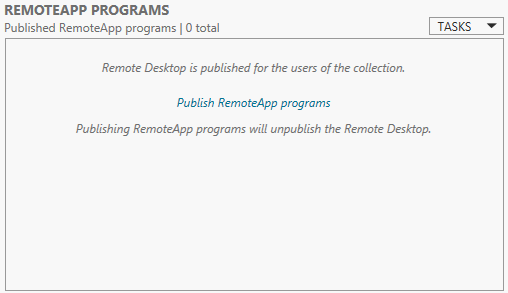
  • In the REMOTEAPP PROGRAMS tile, click Tasks, and then click Publish RemoteApp Programs.

Remoteapp23

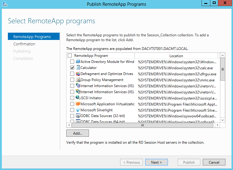
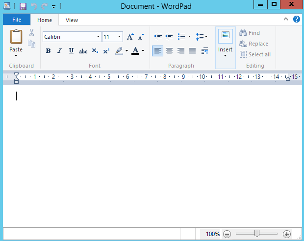
  • On the Select RemoteApp Programs page, select Calculator and Wordpad, and then click Next.

Remoteapp24

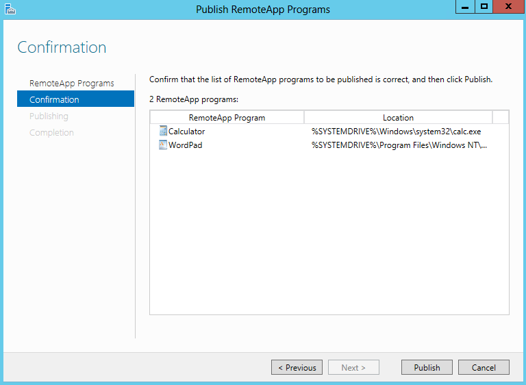
  • On the Confirmation page, click Publish.

Remoteapp25

  • When the RemoteApp program is published, click Close.
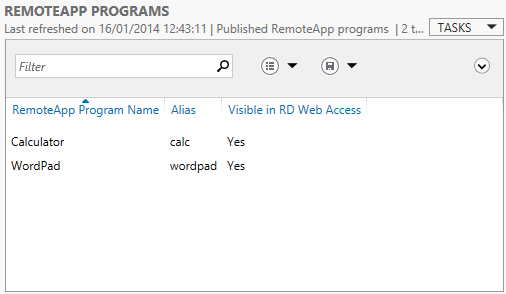
  • You should now see the Apps as per below screenprint

Remoteapp26

  •  Next, Enable the default connection URL using Group Policy
  • Log on to the domain controller as the Domain\Administrator user account.
  • On the domain controller, open Group Policy Management. Click Start, type Group Policy Management, and then click Group Policy Management..
  • Expand Forest: dacmt.local, and expand Domains, and then expand dacmt.local.
  • Right-click Default Domain Policy, and then click Edit.
  • Navigate to User Configuration -> Policies ->Administrative Templates -> Windows Components -> Remote Desktop Services -> RemoteApp and Desktop Connections.
  • Double-click Specify Default Connection URL, and then click Enabled.
  • In the Default Connection URL box, type https://dacvtst001.dacmt.local/RDWeb.
  • Click OK
  • Next we need to configure the file type association
  • Log on to the Remote Desktp Session Host server as the Domain\Administrator user account.
  • Server Manager will start automatically. If it does not automatically start, click Start, type servermanager.exe, and then click Server Manager.
  • On the left side of the window, click Remote Desktop Services.
  • Under Collections, click SessionCollection.
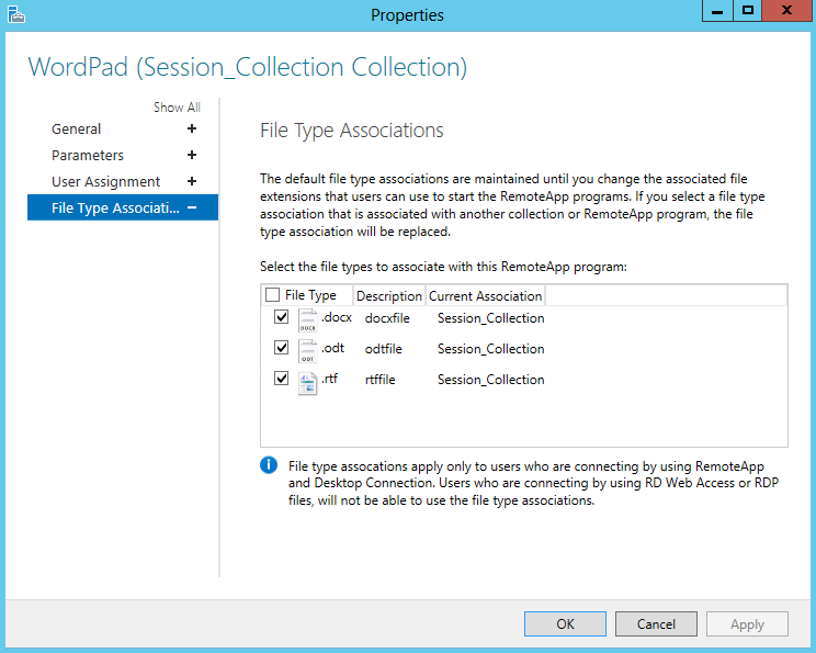
  • Under the REMOTEAPP PROGAMS heading, right-click WordPad, and then click Edit Properties.
  • Click File Type Association.
  • Select the .docx, .odt, and .rtf

Remoteapp27

  •  Next Configure DNS Feed Lookup for RemoteApp and Desktop Connections.
  • Log on to the domain controller as the Domain\Administrator user account.
  • On the domain controller, open DNS Manager. Click Start, type DNS, and then click DNS.
  • Right-click the forward lookup zone where you want to create the TXT record, and then click Other New Records.
  • Click Text (TXT), and then click Create Record.
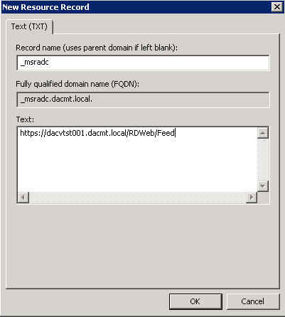
  • In the Record name (use parent domain if left blank) box, type _msradc.
  • In the Text box, type https://dacvtst001.dacmt.local/RDWeb/Feed

Remoteapp30

  • Click OK
  • Next Test Published RemoteApp Program using RD Web Access
  • Log on to the your Windows 7 or Windows 8 computer as the Domain\Administrator user account.
  • Open Internet Explorer. To open Internet Explorer, click Start, and then click Internet Explorer.
  • In the Internet Explorer address bar, type https://dacvtst001.dacmt.local/RDWeb and then press Enter.
  • Click Continue to this website (not recommended).
  • In the Domain/user name box, type your username
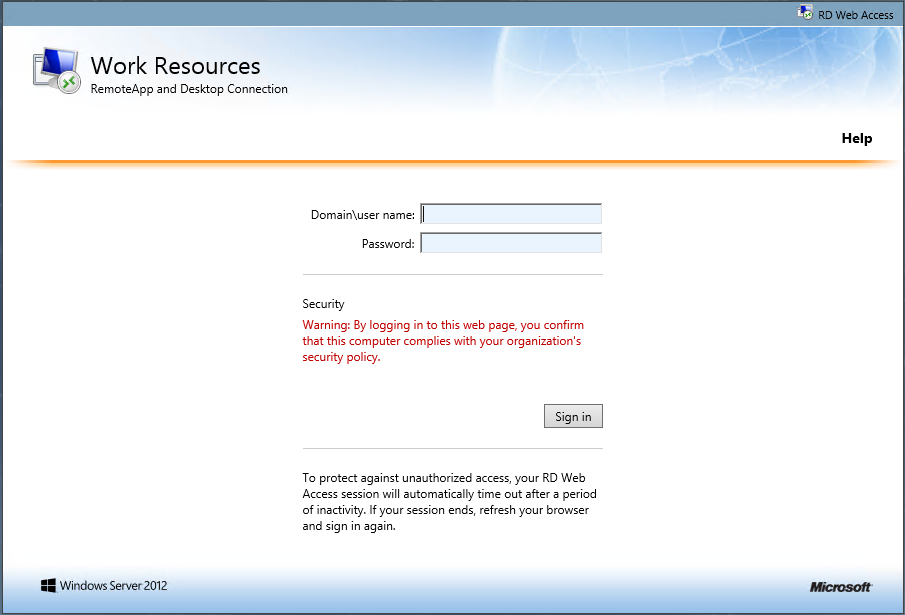
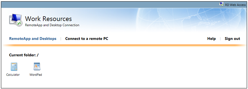
  • In the Password box, type the password for the CORP\Administrator user account, and then click Sign in. You should see the screen below

Remoteapp31

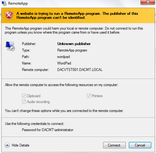
  • Click WordPad, and then click Connect.

Remoteapp32

  • Verify that the WordPad application appears correctly. and then press Enter.

Remoteapp33

  • Hurrah! It works 🙂 🙂 🙂

NAP (Network Access Protection) on Windows Server 2012

keep-out

What is NAP?

Network Access Protection (NAP) is a new technology introduced in Windows Vista® and Windows Server® 2008. (NAP can also be deployed on computers running Windows Server 2008 R2 and Windows 7). NAP includes client and server components that allow you to create and enforce health requirement policies that define the required software and system configurations for computers that connect to your network. NAP enforces health requirements by inspecting and assessing the health of client computers, limiting network access when client computers are deemed noncompliant, and remediating noncompliant client computers for unrestricted network access. NAP enforces health requirements on client computers that are attempting to connect to a network. NAP also provides ongoing health compliance enforcement while a compliant client computer is connected to a network.

In addition, NAP provides an application programming interface (API) set that allows non-Microsoft software vendors to integrate their solutions into the NAP framework.

NAP enforcement occurs at the moment when client computers attempt to access the network through network access servers, such as a VPN server running Routing and Remote Access, or when clients attempt to communicate with other network resources. The way that NAP is enforced depends on the enforcement method you choose.

NAP enforces health requirements for the following:

  • Internet Protocol security (IPsec)-protected communications
  • Institute of Electrical and Electronics Engineers (IEEE) 802.1X-authenticated connections
  • Virtual private network (VPN) connections
  • Dynamic Host Configuration Protocol (DHCP) configuration
  • Terminal Services Gateway (TS Gateway)

Installing NAP

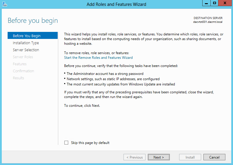
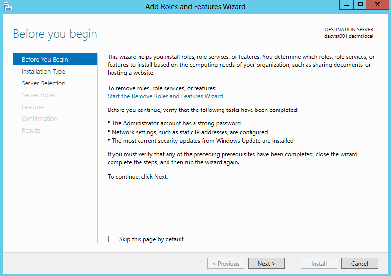
  • Select Add Roles and Features and when the screen below comes up, Click Next

Nap1

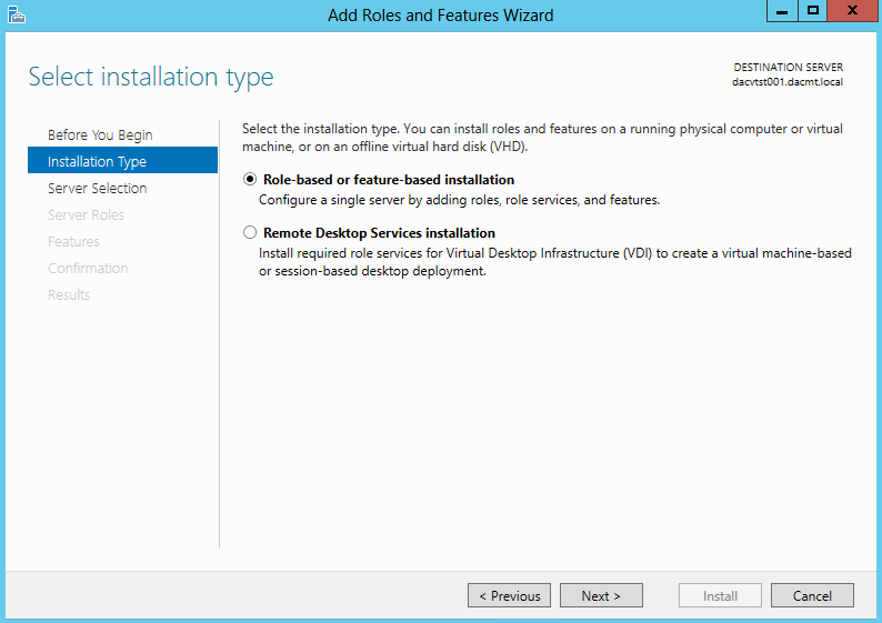
  • Select Role-based or feature based installation

Nap2

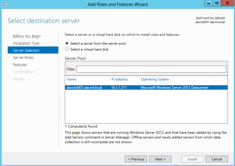
  • Choose your server. I have a test Windows 2012 box called dacvtst001

Nap3

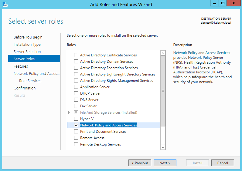
  • Select Network Policy and Access Services

Nap4

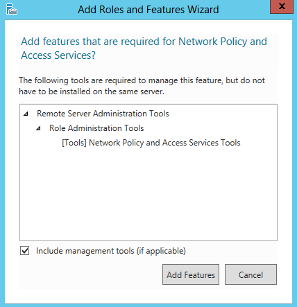
  • Click to Add Features when you select Network Policy and Access Services

Nap5

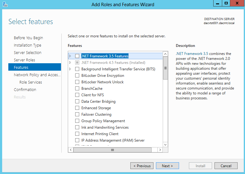
  • Click Next on Select Features

Nap6

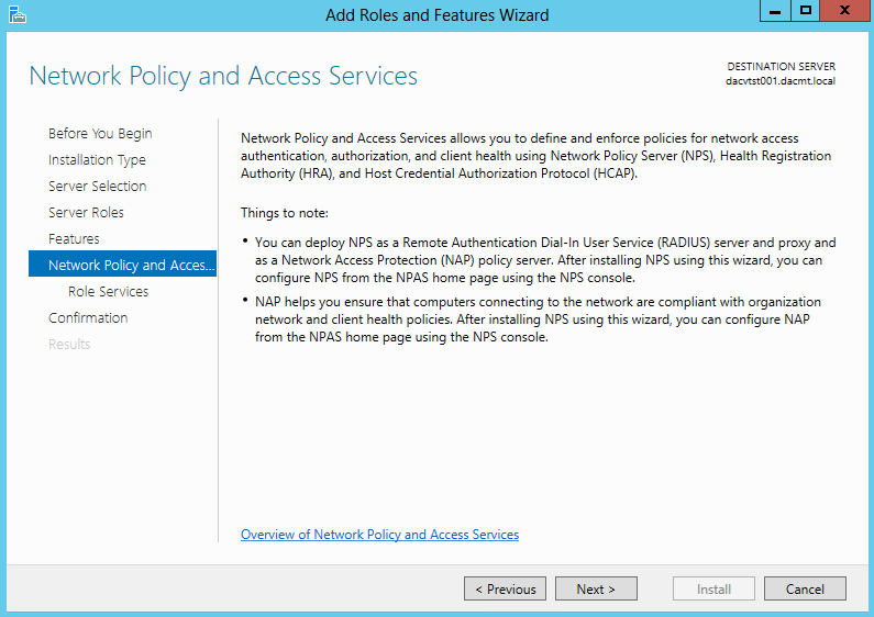
  • Read the Network Policy and Access Services screen

Nap7

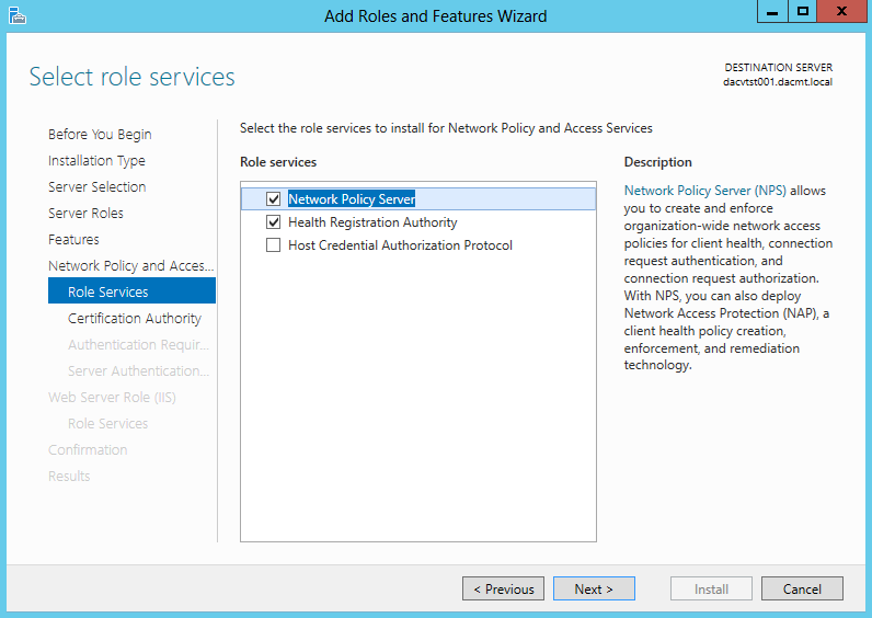
  • The following screenprints show the different descriptions of each Role Service. The first one being the Network Policy Server

Nap8

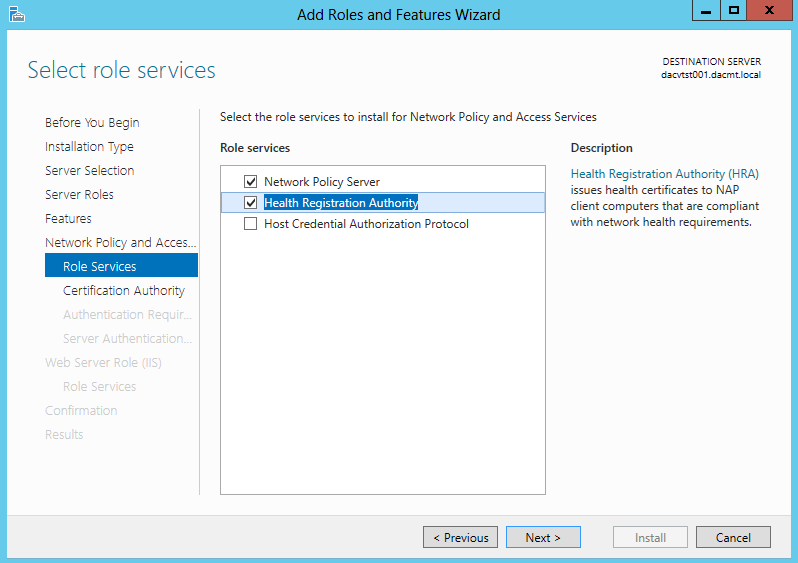
  • The second one being the Health Registration Authority

Nap9

  • The third one being the Host Credential Authorization Protocol
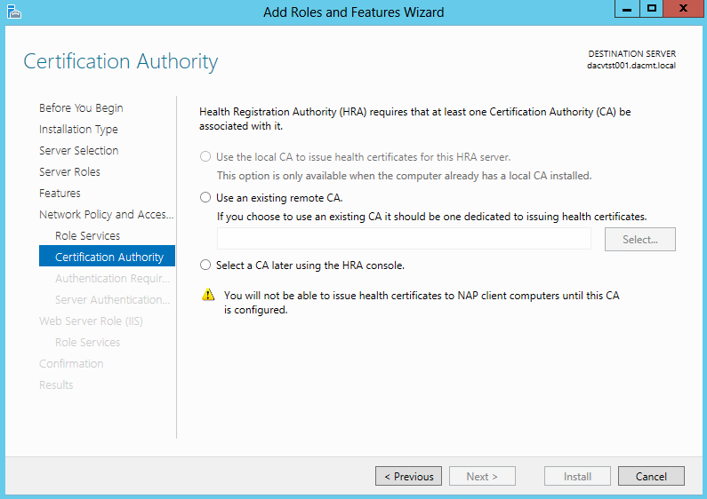
  • Choose your Certificate settings. I chose Select a CA later using the HRA Console as this is just a test system but choose whatever is relevant to your setup

Nap11

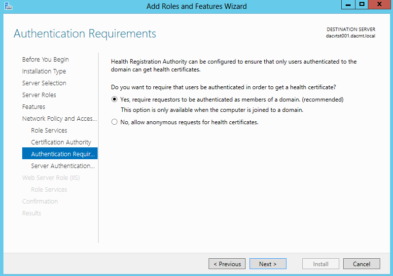
  • Choose Authentication Requirements

Nap12

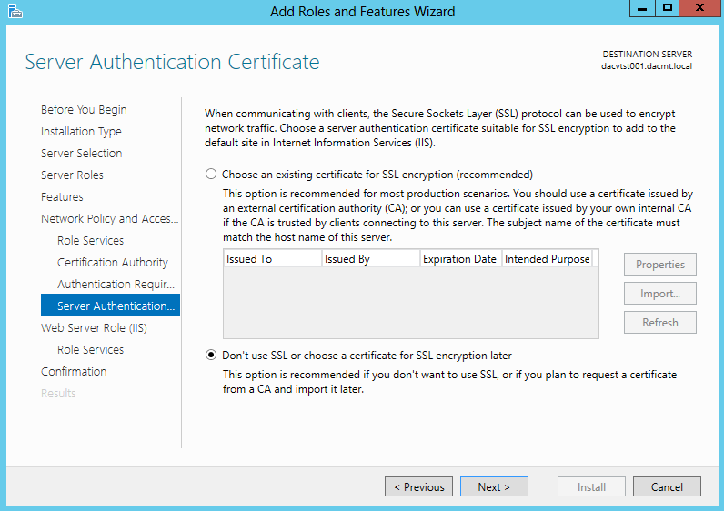
  • Choose your Server Authentication Certificate for encryption

Nap13

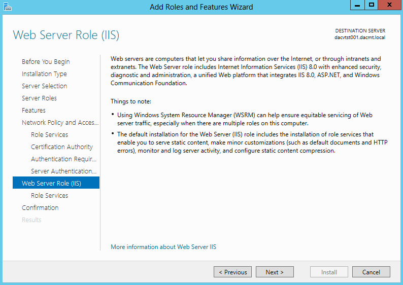
  •  Read the Web Server Role (IIS)

Nap14

  • Select Web Server Role Services Features

Nap15

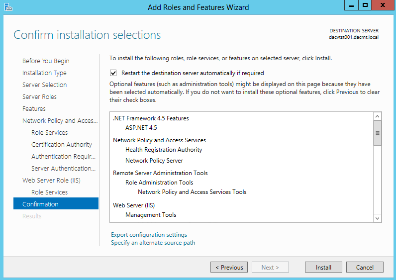
  • Confirm Installation Selections

Nap16

  •  You will also need to install the Group Policy Management Feature
  • In Server Manager, under Features Summary, click Add Features.
  • Select the Group Policy Management check box, click Next, and then click Install.
  • Verify the installation was successful, and then click Close to close the Add Features Wizard dialog box.
  • Close Server Manager.
  • Next once everything is installed and rebooted, hit the Windows Key and Q to see the Aero view of all Applications
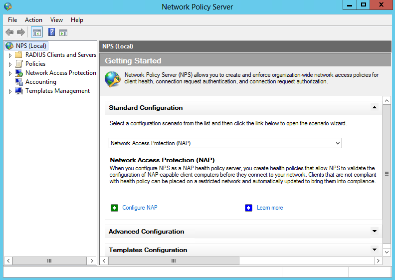
  • Select Network Policy Server and you should see the below screen

NAP1

  • And here is what it looks like with the menus expanded

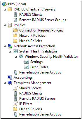
NAP

The NAP wizard helps you configure each NAP component to work with the NAP enforcement method you choose. These components are displayed in the NPS console tree, and include:

  • System Health Validators. System health validators (SHVs) define configuration requirements for computers that attempt to connect to your network. E.g. Configured to require only that Windows Firewall is enabled.
  • Health Policies. Health policies define which SHVs are evaluated, and how they are used in the validation of the configuration of computers that attempt to connect to your network. Based on the results of SHV checks, health policies classify client health status.
  • Network Policies. Network policies use conditions, settings, and constraints to determine who can connect to the network. There must be a network policy that will be applied to computers that are compliant with the health requirements, and a network policy that will be applied to computers that are noncompliant.
  • Connection Request Policies. Connection request policies are conditions and settings that validate requests for network access and govern where this validation is performed.
  • RADIUS Clients and Servers. RADIUS clients are network access servers. If you specify a RADIUS client, then a corresponding RADIUS server entry is required on the RADIUS client device. Remote DHCP servers are configured as RADIUS clients on NPS.
  • Remediation Server Groups. Remediation server groups allow you to specify servers that are made available to noncompliant NAP clients so that they can remediate their health state and become compliant with health requirements. If these servers are required, they are automatically available to computers on the restricted access subnet when you add them to remediation server groups.

Configuring NAP

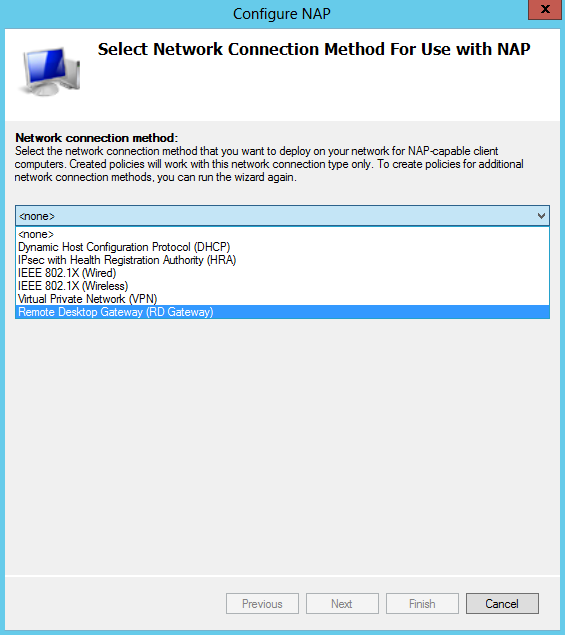
  • In the details pane, under Standard Configuration, click Configure NAP. The NAP configuration wizard will start
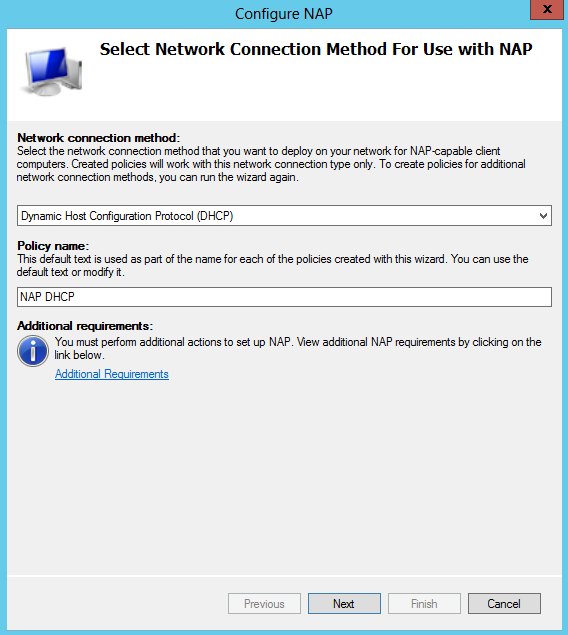
  • Choose Dynamic Host Configuration Protocol (DHCP) Note I already have DHCP installed on this test VM

NAPconfig2

  • You should then see the below

NAPconfig3

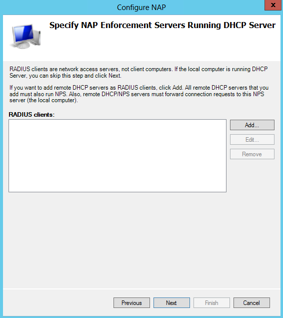
  • Choose the Radius clients. Note I already have DHCP installed so I just click Next

NAPconfig4

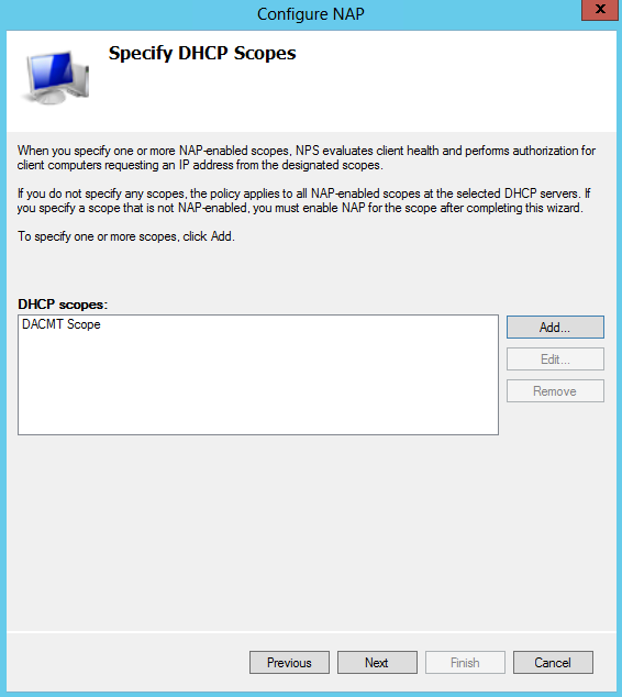
  • Click Add and type a name for your DHCP Scope. Mine is called DACMT scope

NAPconfig5

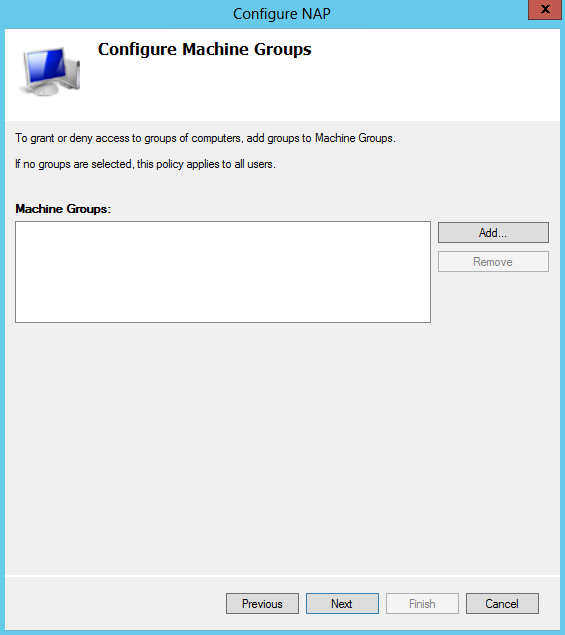
  • Configure Machine Groups. Just click Next

NAPconfig6

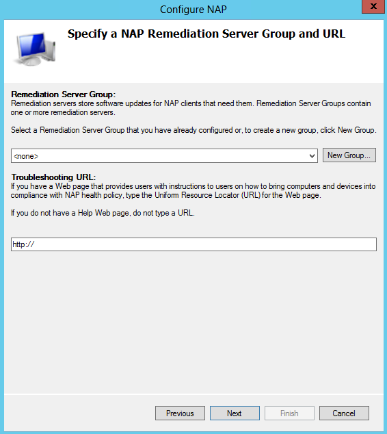
  • Choose Remediation Server Groups. Just click Next here

NAPconfig7

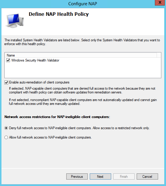
  • Define NAP Health Policy. Verify that Windows Security Health Validator and Enable
    auto-remediation of client computers check boxes are selected, and then click Next

NAPconfig8

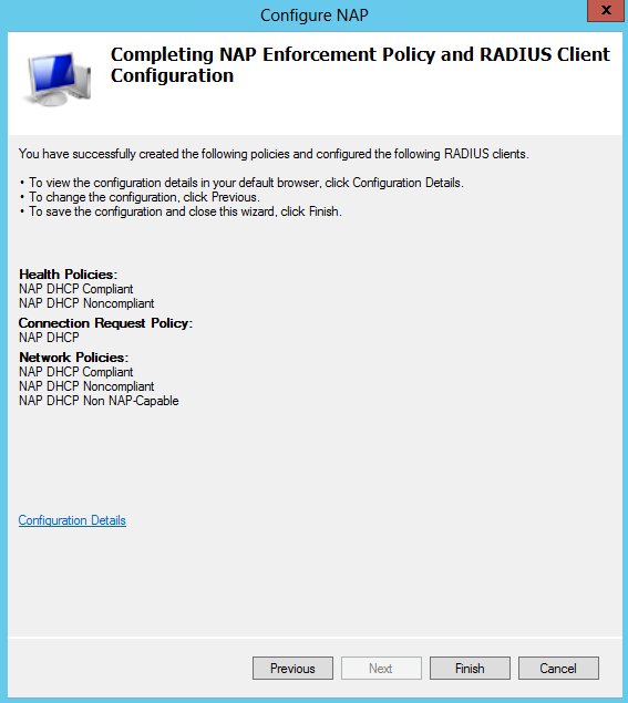
  • On the Completing NAP Enforcement Policy and Radius Client Configuration screen, check the details and click Finish

NAPconfig9

Configure SHVs

SHVs define configuration requirements for computers that attempt to connect to your network.

  • In the Network Policy Server console tree, double-click Network Access Protection, and then click System Health Validators >
  • In the details pane, click Windows Security Health Validator.
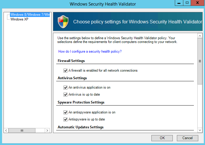
  • In the Windows Security Health Validator Properties dialog box, click Settings.

NAPconfig10

  • Tick whichever Security Health Validations you want to enforce on your network

Enable NAP settings for the scope

  • In the DHCP console, double-click dacvtst001.dacmt.local, and then double-click IPv4
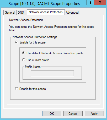
  • Right-click Scope [10.1.1.0] DACMT Scope, and then click Properties.
    On the Network Access Protection tab, under Network Access Protection Settings, choose Enable for this scope, verify that Use default Network Access Protection profile is chosen, and then click OK

NAPconfig11

Configure the default user class

Next, configure scope options for the default user class. These server options are used when a compliant client computer attempts to access the network and obtain an IP address from the DHCP server.

  • In the DHCP console tree, under Scope [10.1.1.0] DACMT Scope, right-click Scope Options, and then click Configure Options.
  • On the Advanced tab, verify that Default User Class is chosen next to User class.
  • Select the 006 DNS Servers check box, in IP Address, under Data entry, type 10.1.1.160, and then click Add.

DHCP1

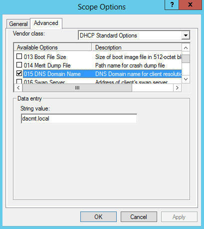
  • Select the 015 DNS Domain Name check box, in String value, under Data entry, type dacmt.local, and then click OK.
  • The dacmt.local domain is a full-access network assigned to compliant NAP clients.

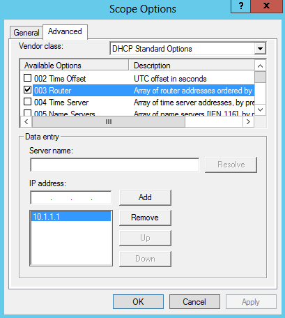
DHCP2

  • Note The 003 Router option is configured in the default user class if a default gateway is required for client computers. Because all computers in the test lab are located on the same subnet, this option is not required.

DHCP3

Configure the default NAP class

Next, configure scope options for the default network access protection class. These server options are used when a noncompliant client computer attempts to access the network and obtain an IP address from the DHCP server.  To configure default NAP class scope options

  • In the DHCP console tree, under Scope [10.1.1.0] DACMT Scope, right-click Scope Options, and then click Configure Options.
  • On the Advanced tab, next to User class, choose Default Network Access Protection Class.
  • Select the 006 DNS Servers check box, in IP Address, under Data entry, type 10.1.1.60, and then click Add.
  • Select the 015 DNS Domain Name check box, in String value, under Data entry, type restricted.dacmt.local, and then click OK. access network assigned to noncompliant NAP clients.
  • Note The 003 Router option is configured in the default NAP class if a default gateway is required for client computers to reach the DHCP server or remediation servers on a different subnet. Because all computers in the test lab are located on the same subnet, this option is not required.

Configure NAP client settings in Group Policy

The following NAP client settings will be configured in a new Group Policy object (GPO) using the Group Policy Management feature on NPS1:

  • NAP enforcement clients
  • NAP Agent service
  • Security Center user interface

After these settings are configured in the GPO, security filters will be added to enforce the settings on computers you specify. The following section describes these steps in detail

  • On dacvtst001, click Start, click Run, type gpme.msc, and then press ENTER.
  • In the Browse for a Group Policy Object dialog box, next to dacmt.local, click the icon to create a new GPO, type NAP Client Settings for the name of the new GPO, and then click OK.
  • The Group Policy Management Editor window will open. Navigate to Computer Configuration/Policies/Windows Settings/Security Settings/System Services.
  • In the details pane, double-click Network Access Protection Agent.
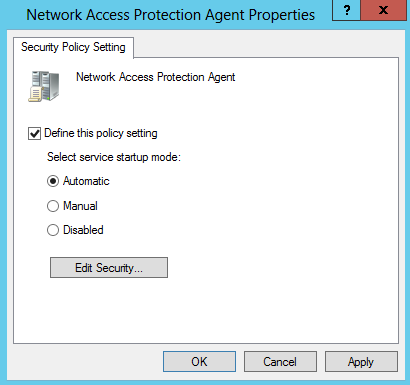
  • In the Network Access Protection Agent Properties dialog box, select the Define this policy setting check box, choose Automatic, and then click OK.

NAPconfig12

  • In the console tree, open Network Access Protection\NAP Client Configuration\Enforcement Clients.
  • In the details pane, right-click DHCP Quarantine Enforcement Client, and then click Enable.

NAPconfig13

  • In the console tree, navigate to Computer Configuration\Policies\Administrative Templates\Windows Components\Security Center.
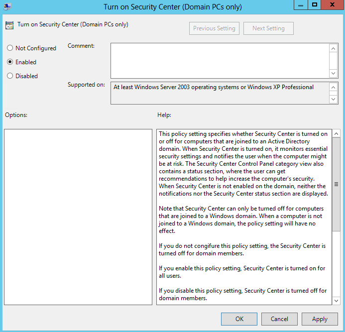
  • In the details pane, double-click Turn on Security Center (Domain PCs only), choose Enabled, and then click OK.

NAPconfig14

  • Close the Group Policy Management Editor window.
  • If you are prompted to apply settings, click Yes

Configure security filters for the NAP client settings GPO

Next, configure security filters for the NAP client settings GPO. This prevents NAP client settings from being applied to server computers in the domain.

  • On dacvtst001, click Start, click Run, type gpmc.msc, and then press ENTER.
  • In the Group Policy Management Console (GPMC) tree, navigate to Forest: dacmt.local\Domains\Contoso.com\Group Policy Objects\NAP client settings.
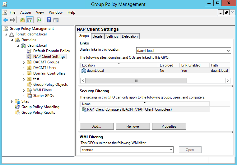
  • In the details pane, under Security Filtering, click Authenticated Users, and then click Remove.
  • When you are prompted to confirm the removal of delegation privilege, click OK. In the details pane, under Security Filtering, click Add.
  • In the Select User, Computer, or Group dialog box, under Enter the object name to select (examples), type NAP client computers group, and then click OK.

NAPconfig15

  • Close the GPMC.

App-V 5 Sequencing

Capture

The Microsoft Application Virtualization (or App-V) Sequencer is a component of the App-V suite used to package your applications to be deployed to systems using the App-V Client. Properly sequencing applications is the key to a successful App-V implementation.  As such, it’s important to follow Microsoft’s recommended practices and be aware of the different options when sequencing.

This blog follows from an initial blog covering App-V 5 features and how to install the App-V 5 Management Server. Click here to read more

Note: I am using App-V 5 RDS Windows Server 2012. The APP-V Sequencer runs on Windows 2012 and my App-V Client runs on a Windows Server 2012 Terminal Server for testing

Sequencer Workstation Configuration

Proper configuration of the sequencing station is imperative to ensure that applications will function properly when streamed to a client.  Microsoft recommends the following configuration when sequencing:

  • Sequence on a machine that matches the Operating System and configuration level for the target clients. Microsoft has clarified its support stance since 4.2. Sequencing on Windows XP and deploying to Windows Vista is not a supported scenario. If you choose to sequence on one Operating System and deploy to another then you do so at your own risk.  In addition to the Operating System, you want to make sure your sequencer is at the same service pack and hot fix level of your deployed workstations.
  • If Microsoft Office is part of the base image of the client, then include it as part of the base image of the sequencer.  Many applications will install differently if they recognize that Microsoft Office is already installed on the machine.  Thus, if an application is expected to integrate with Microsoft Office, it’s best to attempt sequencing on a machine with Office already installed and activated. This assumes that a Microsoft Office suite will be installed locally on all client PCs. In addition you may want to install any other programs that could be used by the application you are sequencing if they are not going to be a part of the sequence.
  • Create an ODBC DSN setting as part of the Sequencer base image.  If no ODBC DSN setting exists on the base Sequencer image and the application being packaged creates one, the entire registry key associated with ODBC settings will become virtualized.  This will prohibit the packaged application from seeing any ODBC DSN settings that exist on the base client machine.  If an ODBC entry already exists on the Sequencer machine, only the ODBC settings will become virtualized, and the ODBC settings on the Client will be merged with the ODBC settings in the package. The following locations can be checked to determine ODBC information was captured:
  • Search for odbc.ini: It will be located in the VFS\%CSIDL_WINDOWS% folder
  • HKLM\Software\ODBC\ODBC.INI\ODBC Data Sources
  • HKCU\%SFT_SID%\Software\ODBC\ODBC.INI
  • Add a dummy printer device as part of the Sequencer base image. Printers act in the same manner as ODBC settings.  It is necessary to include a dummy printer device in the sequencer PC image.  For step by step instruction on how to create a dummy printer device refer to Appendix B.
  • Setup your sequencer machine with multiple partitions. It is recommended that the sequencer machine be configured with at least two primary partitions. The first partition C:, should have the operating system installed and should be formatted as NTFS. The second partition Q:, is used as the destination path for the application installation and should also be formatted as NTFS.
  • Temp Directory. The sequencer uses the %TMP%, %TEMP%, and its own Scratch directory for temporary files.  These locations should contain free disk space equivalent to the estimated installation size. The scratch directory is where the sequencer will temporarily store files generated during the sequencing process. You can check the location of the Scratch directory by launching the sequencer, clicking Options from the Tools menu, clicking the Paths tab, and then noting the Scratch Directory box. Placing the temp directories and the scratch directory on different hard drive spindles can improve performance during sequencing.
  • Sequence using Virtual PC. Most applications will be sequenced more than once. This may be due to additional configuration changes or simply starting over to correct a mistake. The point is that you will be going back to your original configuration on the PC several times. To help facilitate this you may want to use a Virtual Machine. This will let you sequence an application and with a simple click of a button revert back to a clean state so you can continue sequencing with no down time. Additionally whenever you start a new sequence you will want to do so on a clean system.
  • Shutdown Other Programs. Processes and scheduled tasks that normally run on your computer can slow down the sequencing process and cause irrelevant data to be gathered during sequencing. These programs should be shutdown before you begin sequencing. Some of these programs include:
  • Windows Defender
  • Antivirus Software
  • Disk defragmentation software
  • Windows Search
  • Microsoft update
  • Any open Windows Explorer session

Note: The sequencer workstation should be fully scanned for viruses and malware and then the anti-virus and anti-malware software should be disabled before creating a snapshot image of the sequencer workstation

Installing and using the App-V 5 Sequencer

I am going to be using a newly built Windows 2012 Virtual Server which has had a base build + updates.

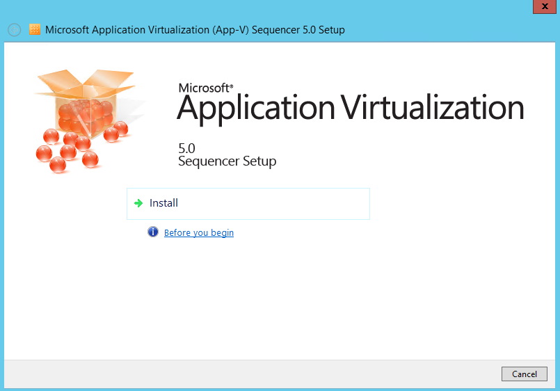
  • First of all install the APP-V Sequencer
  • Click Install

APPV1

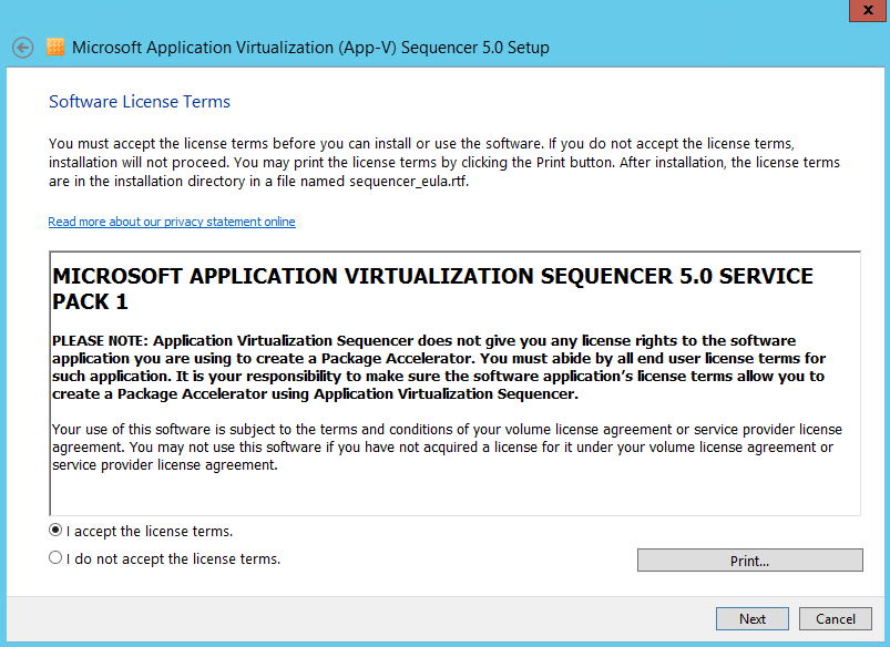
  • Accept the License Agreement

APPV2

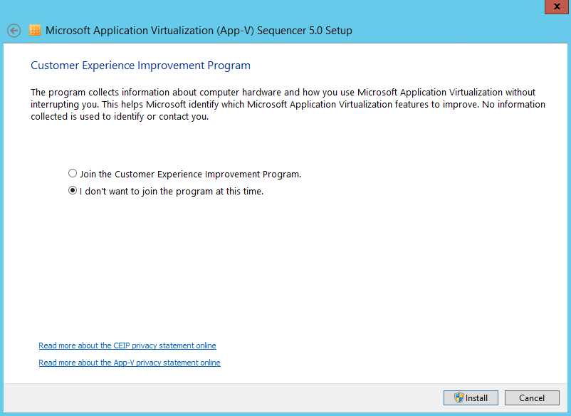
  • Choose whether to join the Customer Experience Improvement Program and click Install

APPV3

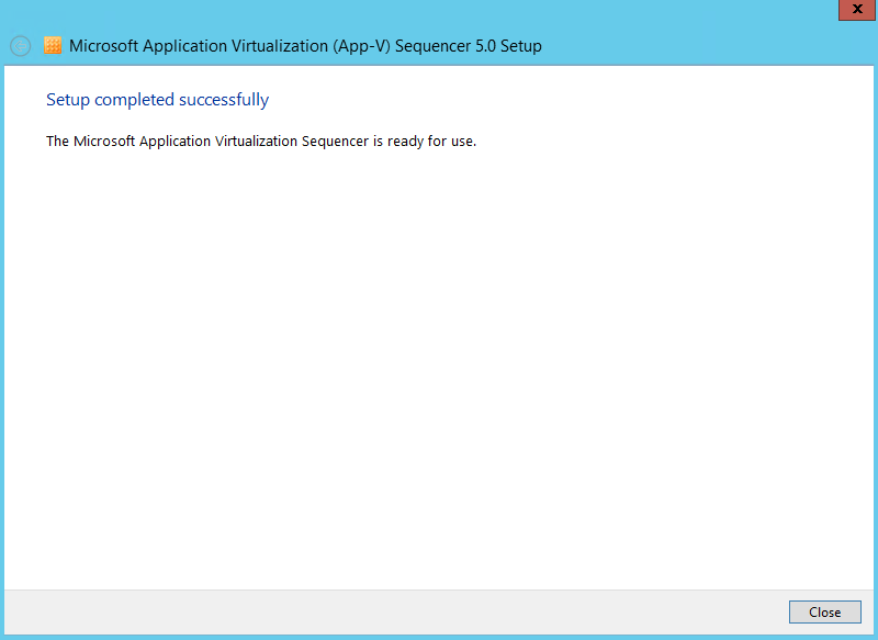
  • Here Setup should have completed successfully

APPV4

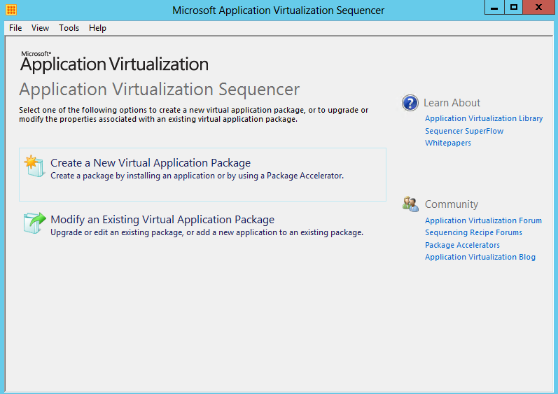
  • Hold down the Windows key and Q to get the aero screen showing all your applications and click on Microsoft Application virtualization Sequencer which will then pop up the box below
  • Click Create a new Virtual Application Package

APPV5

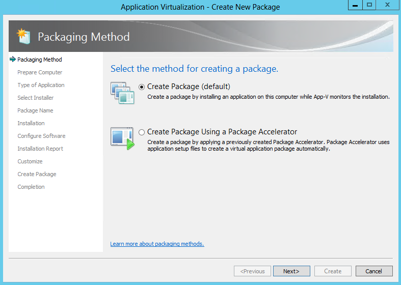
  • Select Create Package and click Next

APPV6

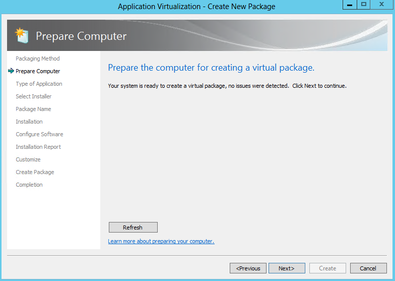
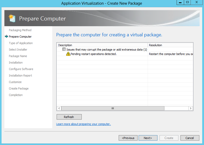
  • Next, the Sequencer examines the current operating environment to evaluate running processes or conditions that are in place (e.g. the Sequencer has not been reverted to a clean state after a previous sequencing operation, or there are pending reboot operations) that might prevent successful sequencing. See example below

APPV7

  • It should now look like the below when everything is ok

APPV8

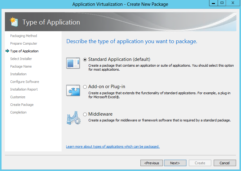
  • Choose the type of application. Click Standard Application (default)
  • Standard Application (Default) Select this option when sequencing a single application or suiting multiple applications into the same virtual application package
  • Add-on or Plug-in. Select this option when sequencing multiple applications in separate virtual application packages and linking them using a Connection Group.  This option can also be used when packaging Add-ons or Plug-ins for locally installed applications like Internet Explorer.
  • Middleware. Select this option when sequencing multiple applications in separate virtual application packages and linking those using Connection Groups.  This option will first create the application package for the middleware component and then create the second virtual application package that will contain the primary application
  • Click Next

APPV9

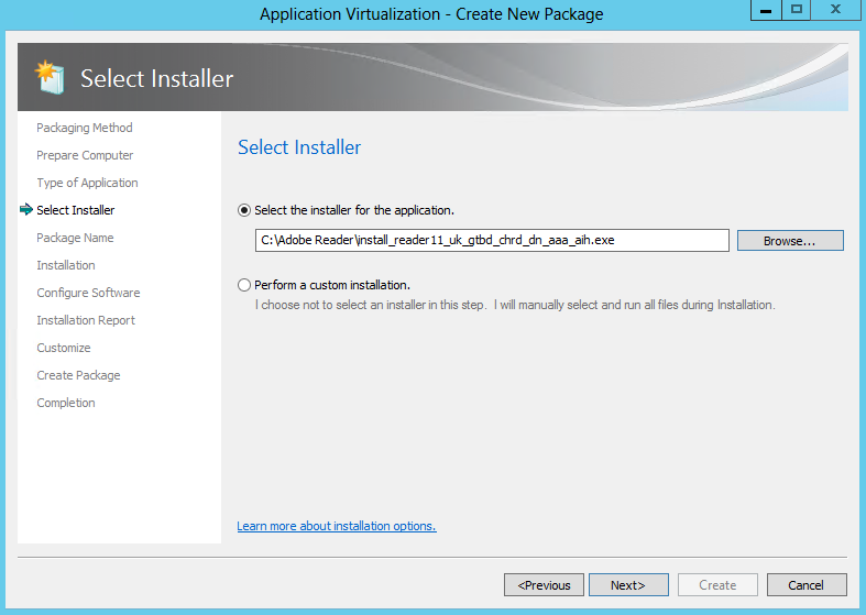
  • Select the Installer for the application is the first option. An “installer” can be any executable file designed to install the desired application.  The Sequencer will automatically launch the installer when it activates monitoring.
  • Alternatively, “Perform a custom installation” can be selected.  This option causes the sequencing wizard to enter monitoring and then wait for manual launching installation tasks.  This option is often useful when sequencing applications that may not have an install or setup file such as applications that copy from a network share

APPV10

  • I am going to use the Adobe Reader 11 installer

APPV11

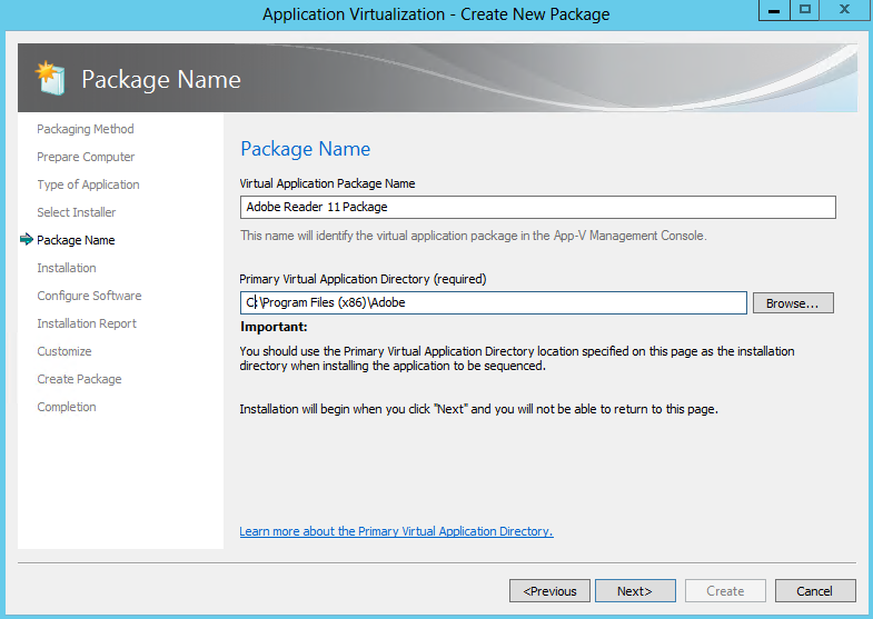
  • Select a package name, typically something descriptive of the vendor, software and version.  This name is independent of the Primary Virtual Application Directory, but should be noted for saving the package. Saving the package in a directory named for the package name is recommended.  At the package name screen, select the Primary Virtual Application Directory.
  • The Primary Virtual Application Directory is the directory that will contain all files for the sequence.  It is recommended to define the application’s default installation directory (example C:\Program Files (X86)\directory) as the Primary Virtual Application Directory.
  • Click Next

APPV20

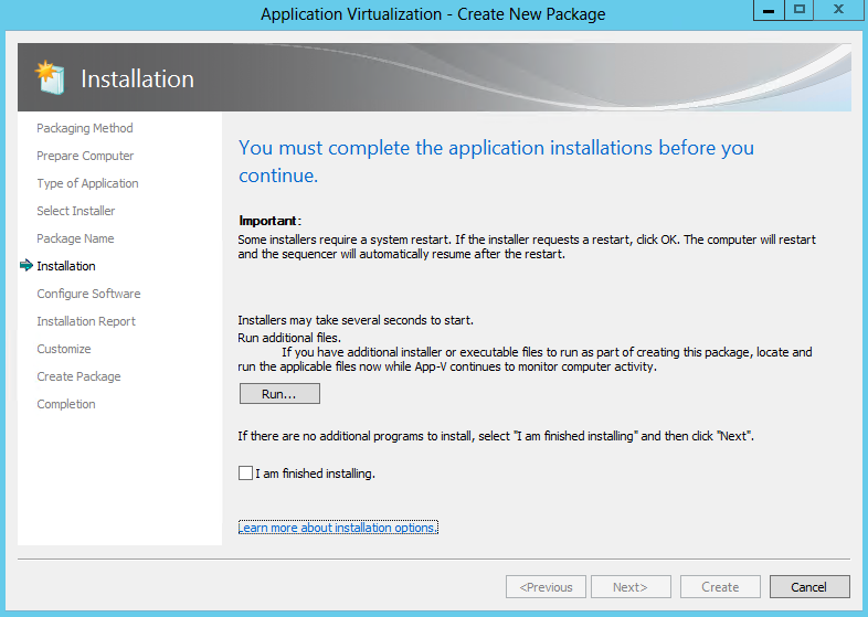
  • When multiple installers are required to create the package, click Run after the completion of each installer, select the next installation program, or manually launch the installer until all installers have been successfully installed.
    Once all installations are complete, select the I am finished installing check box and click Next.The installer popped up automatically or you can manually click on your exe to run the software

APPV13

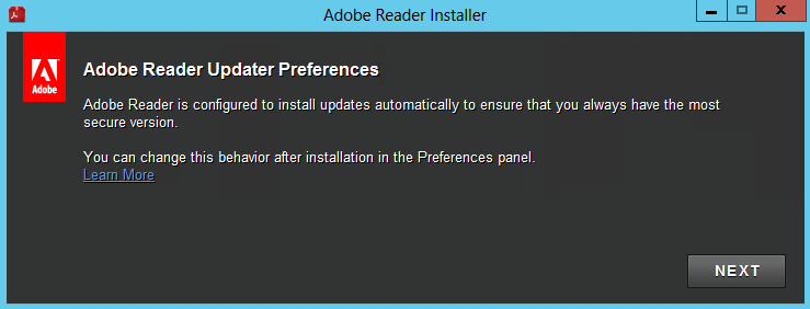
  • The application you selected should start automatically

APPV14

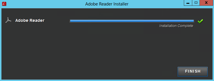
  • Click Finish when the application has finished

APPV15

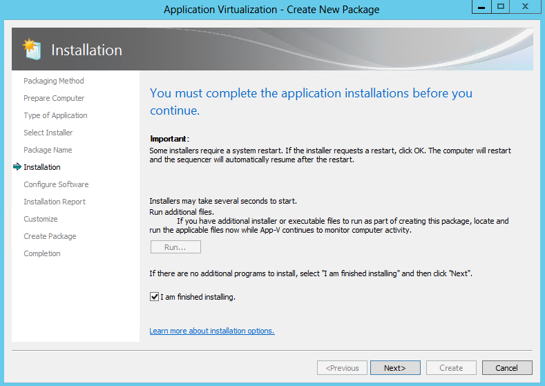
  • Put a tick in I am finished installing

APPV16

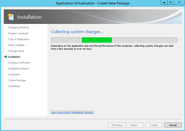
  •  The below screen will run

APPV21

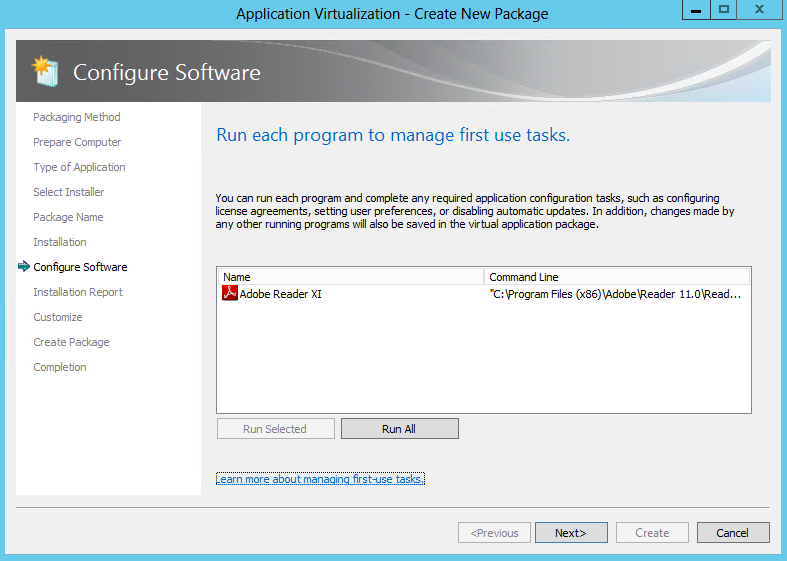
  • Many applications have first-run tasks such as accepting license agreements, etc.  At this stage, execute the application(s) at least once by selecting the application and clicking the “Run Selected” or “Run All” buttons (multiple executions are recommended to ensure any second-run tasks are executed).  Also, it is during this execution that any applicable application configuration changes should be made.
  • Note: This screen is also running in monitoring mode.  It is possible to manage the tasks for programs that are not listed on this page by launching them outside of the Sequencer using Windows Explorer
  • Then the following screen – Configure Software will appear

APPV17

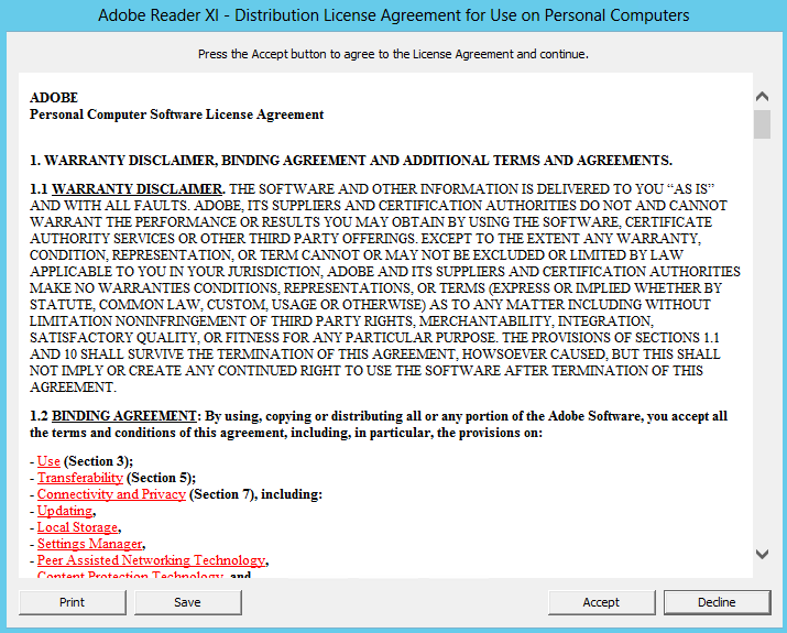
  • Example License Acceptance from Adobe on first run

APPV18

  • Click Next
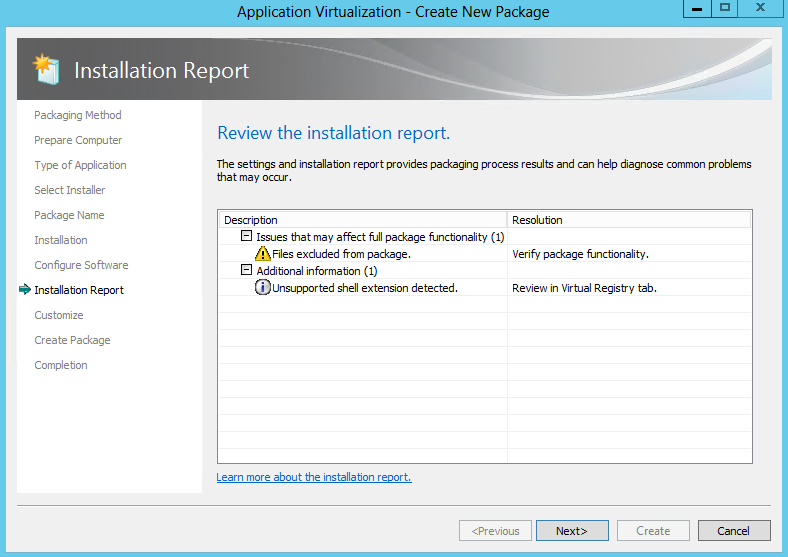
  • Review the Installation Report
  • The Sequencer detects common issues during sequencing. The Installation Report page of the wizard displays diagnostic messages categorized into Errors, Warnings, and Info depending on the severity of the issue. Double click an item in the report to view detailed information about the issue as well as suggestions for resolution. Messages from the system preparation report as well as the installation report are summarized upon package completion and are saved along with the package in a report.xml file.

APPV19

  • Excluded Files
  • Drivers
  • COM+ System differences
  • SxS Conflicts
  • Shell Extensions
  • Files or registry entries that were not captured during monitoring
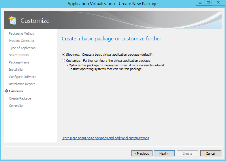
  • Choose Stop now if the sequence will not benefit from further customization and select Create.
  • However, often there are other steps remaining under the Customise Option such as:
  • Splitting the package into feature blocks to reduce the streaming requirement and save bandwidth.
  • Selecting additional client operating systems that will be permitted to receive this package.
  • Changing shortcuts and file type associations.
  • Modifying registry settings and adding and deleting files in the package.
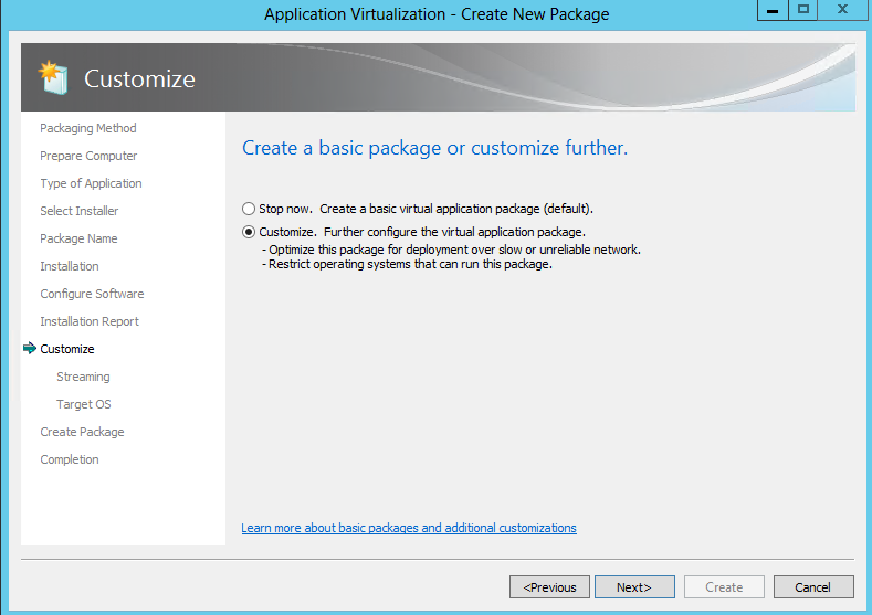
  • When additional customization is required select Customize and Next to continue the sequencing process and allow additional changes prior to the creation of the package.

APPV22

  •  Choose Customise

APPV23

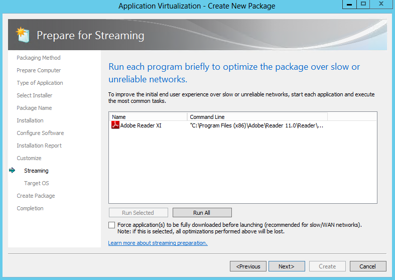
  • Prepare for Streaming
  • Feature blocks are designed to optimize the applications for streaming (if applicable), creating a minimum launch threshold that allows launching larger applications as soon as enough of the package has been downloaded and does not require downloading the entire package.  This enables users access to applications more quickly upon deployment.
  • Feature blocks also reduce the total network bandwidth used when launching the application for the first time and saves hard disk space on the client by leaving less-used data on the server until it is specifically called by the user.
  • Creating feature blocks is recommended unless the deployment method for virtual application packages is only completed with System Center Configuration Manager for Download Locally and Run option or via MSI for standalone mode clients.
  • At the Prepare for Streaming screen, feature blocks are created based on individual, selection of, or all applications

APPV24

  • Select and run each shortcut from the package that users execute in typical day-to-day operations.  Then, perform the common tasks that typical users perform within each particular application during normal operations.
  • During this process, the Sequencer tracks which specific pieces of the package’s resources are being executed and includes them in the primary feature block.  When a user launches the application for the first time, the App-V client will stream and cache just the data within the primary feature block over the network and will launch the application.
  • Any pieces of the package not included in the primary feature block are placed in the secondary feature block and reside on the server or storage location until specific resources from within the secondary feature block are called by the App-V client.  Those pieces are streamed on-demand and cached on the client.
  • Clicking ‘Next’ without launching any shortcuts enables the entire content of the package streaming and cached “on-demand” on the App-V client.  Typically, this is done for very small application packages if streaming the entire package does not cause any network bandwidth concerns.
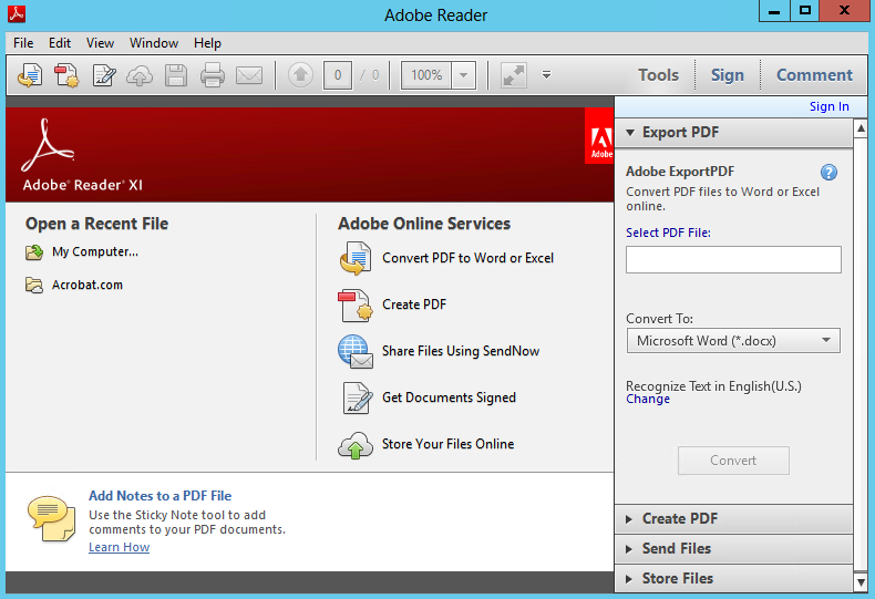
  • Normally, the client launches the application after the primary feature block has been downloaded to improve launch time.  By selecting the “Force application(s) to be fully downloaded before launching” option, the client will be forced to wait until all blocks of the virtual application package have been downloaded before launching the application.  This is useful when clients may be running this package over slow WAN links.Launch your application and then close it again
  • Launch Adobe and make any modifications then close this again

APPV25

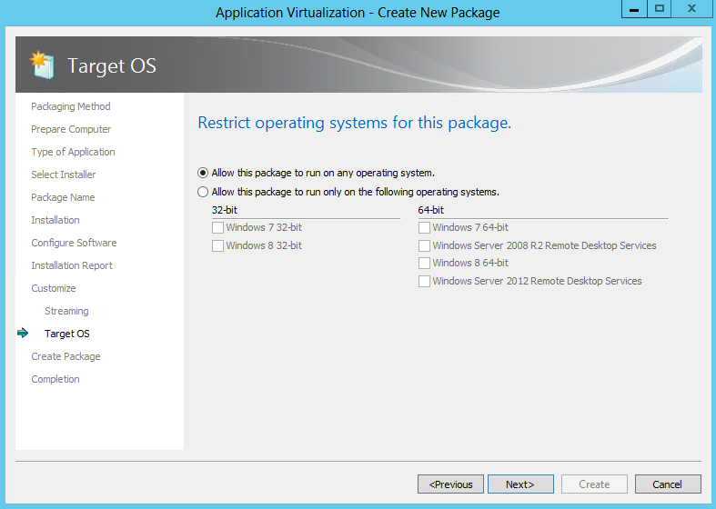
  • Now what Operating systems do you want to allow this to run on

APPV26

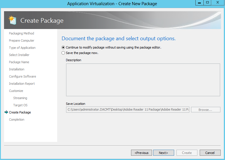
  • You can now continue to modify the package or save the package now. For the purpose of seeing all the options, click to continue

APPV27

  • You should now have a Package completed screen

APPV28

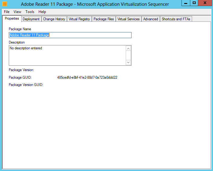
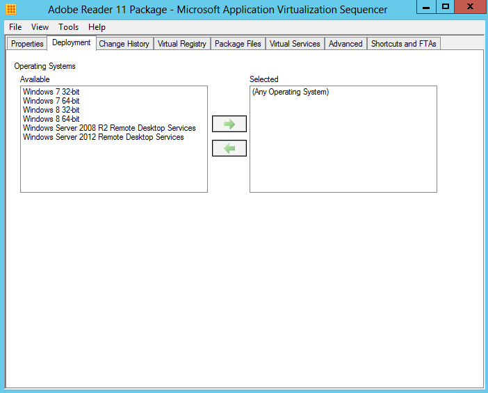
  • The next screen which is the package editor, is composed of several tabs that enable further configuration modification prior to saving the package.  These tabs include options to modify the various settings
  • Properties

APPV29

  • Deployment

APPV30

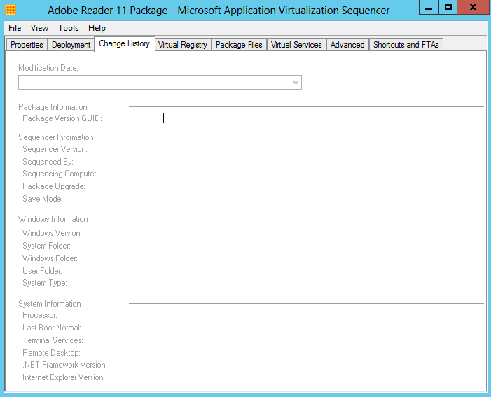
  • Change History

APPV31

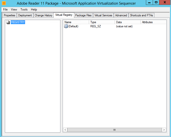
  • Virtual Registry displays the current virtual registry configuration and allows for deleting or renaming existing keys and values as well as adding new keys and values in both the HKLM (Machine) and HKUSERS (Users) hives. Where the same registry key may exist on the local system as well as in the virtual application package, the virtual key can be configured to either merge with the local configuration or override the local configuration

APPV32

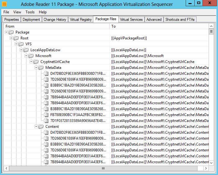
  • The Package Files tab displays the current list of files and folders added to the package and allows for the addition or deletion of files.  However, this interface should not be used to add or remove files in the package if the package has previously been optimized for streaming by way of creating feature blocks

APPV33

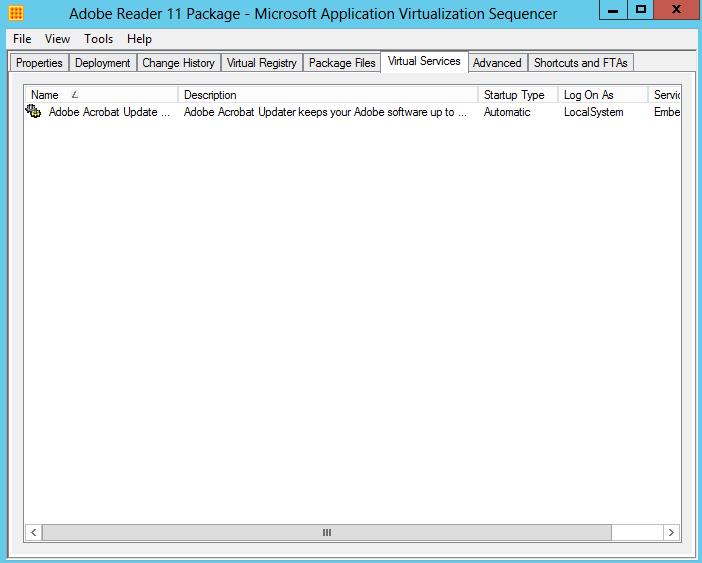
  • The Virtual Services tab displays the current configuration of virtualized application services and allows for changing the Startup Type, Log On and Dependencies configuration of virtualized services.
  • Note: The services tab is read-only.  In order to disable a virtual service, set the service’s properties during monitoring using Services.msc or by utilizing a dynamic configuration file post-sequencing.

APPV34

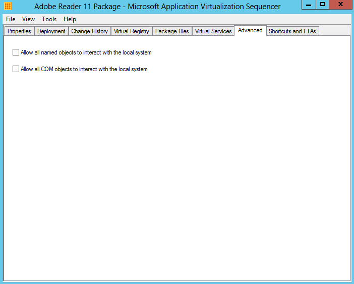
  • The Advanced tab provides an option to enable visibility of named and COM objects in an App-V package to the local system to improve the usability of some application functions.  Local system visibility may be useful for such tasks as virtualizing legacy versions of Microsoft Outlook

APPV35

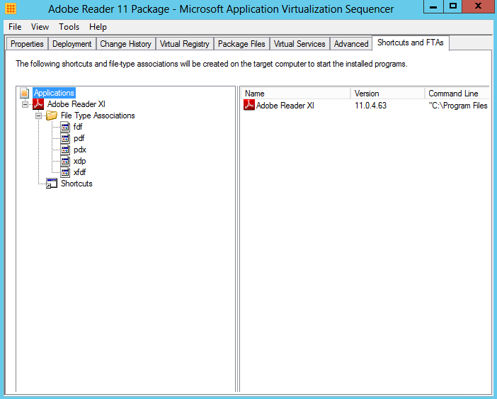
  • The Shortcuts and FTAs tab provides the ability to customize the Shortcuts and File Type Associations for the applications identified during monitoring.  Applications may have to be added or removed from this list, based requirements for the final package.  In addition, with web-based applications it is often necessary to add Internet Explorer as an application where the web-based application requires launching Internet Explorer as a dependency.
  • Each application can be modified to change the name, icon, file type associations, and locations for shortcuts on destination computers.

APPV36

  • When you are finished making customizations, select the File pull-down menu and select Save or Save As to save the virtual application package.
  • As a recommended best practice, create a new folder for the package using the Package Name and save the package in this folder.  Once saved, copy the package folder to a preferred package repository.

APPV37

  • It should show you the below screen!

APPV38

  •  Next you need to open up the App-V 5 Web Console and connect to App-V
  • Click Add or Upgrade Packages

APPV40

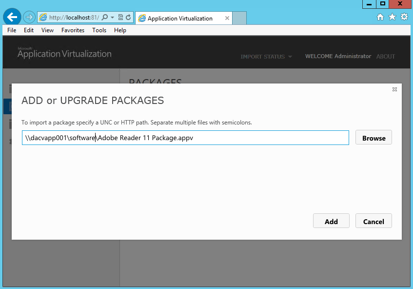
  • Type in the Share or URL name and click Add. I set up a share called software which contains my Adobe App-V Package.
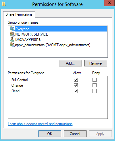
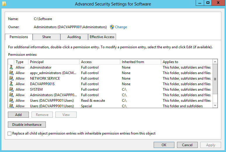
  • You must make sure you have added the App-V Server name e.g. dacvapp001$ to the Share and NTFS Permissions of the shared folder

APPV43

  • and

APPV44

  • Now add your package via UNC or HTTP Path
  • I also found instead of putting my server name, I could put localhost for the servername

APPV41

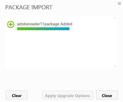
  • If the package import is successful, you will see the below

APPV42

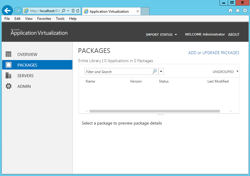
  •  You will then be back to the main console showing you your added package

Appvseq

  • Underneath here you can see the following

Appvseq2

  •  Click on AD Access and add the AD Groups you want to have access. As you can see I have just added my Administrators Group as this is a test lab
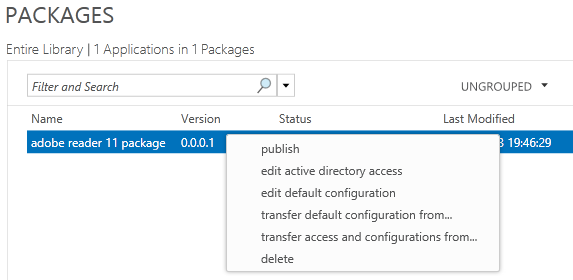
  • Now you need to right click on your App and select Publish

Appvseq3

  • It should now say Published

Appvseq4

  • Next… In order to stream the app to a client, we need to have the App V 5 Client installed on a VM so I have another VM where we will install this software as per below instructions
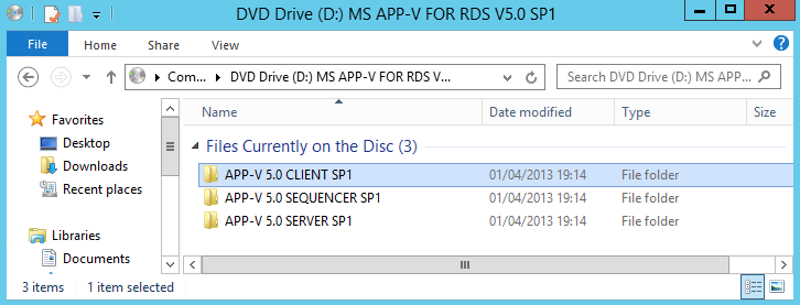
  • Attach the App V 5 ISO to your machine and click on APP-V Client 5 SP1

Appvseq5

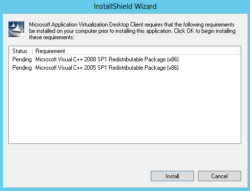
  •  The installer will start and will install any pre-requisites as per below

Appvseq6

  • You are now ready to install the client
  • Follow the Install Wizard
  • You should then see the following screen when complete

appv40

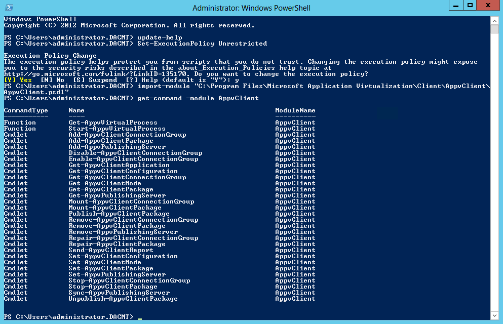
  • Next Open PowerShell as an Administrator and type the following commands
  • Update-Help
  • Set-ExecutionPolicy Unrestricted
  • Import-Module “C:\Program Files\Microsoft Application Virtualization\Client\AppvClient\AppvClient.psd1”
  • Get-Command – module AppvClient

appv41

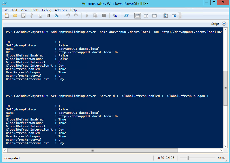
  • Add-AppVPublishingServer -name dacvapp001.dacmt.local -URL http://dacvapp001.dacmt.local:82
  • Set-AppVPublishingServer -ServerID 1 -GlobalRefreshEnabled 1 -GlobalRefreshOnLogon 1

appv42

  • Close PowerShell
  • Restart the Server
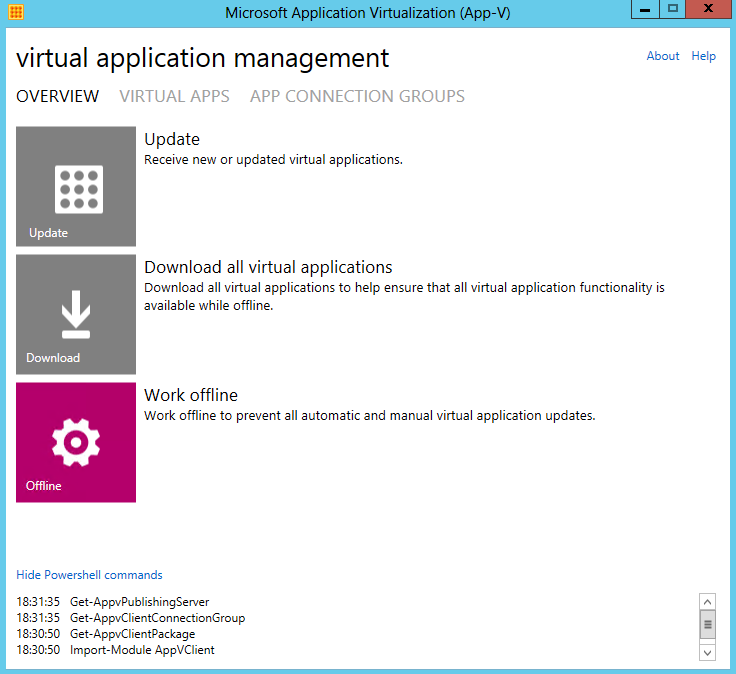
  • Open the AppvClient
  • Click Update and wait a few moments

appv40

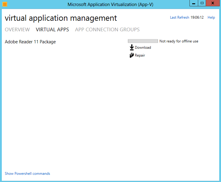
  • Next Click Virtual Apps on this screen to check that your package is there

appv43

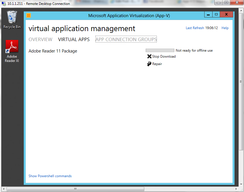
  • Click Download
  • Lo and Behold, if everything is ok then you should see the Adobe Reader icon on your desktop
  • Go and have a glass of wine phew! 😉

appv44


Microsoft App-V v5

APPV

What is Microsoft App-V?

Microsoft Application Virtualization is an application virtualization and application streaming solution from Microsoft

  • Allows applications to be deployed (“streamed”) in real-time to any client from a virtual application server
  • Removes the need for traditional local installation of the applications, although a standalone deployment method is also supported
  • The App-V stack sandboxes the execution environment so that an application does not make changes directly to the underlying operating system’s file system and/or Registry, but rather contained in an application-specific “bubble”
  • App-V applications are also sandboxed from each other, so that different versions of the same application can be run under App-V concurrently, and so that mutually exclusive applications can co-exist on the same system.
  • Supports policy based access control; administrators can define and restrict access to the applications by certain users by defining policies governing the usage.

App-V Deployment Options

Microsoft offers three deployment options. These three options are significantly different from an architectural standpoint: Dedicated App-V Management Server, Shared System Center Configuration Manager Architecture, and “Stand-alone” Mode wherein the application may be delivered manually.

Dedicated App-V management server

The App-V system architecture is composed of the following components:

  • ‘Microsoft Systems Center Virtual Application Server, also called App-V Application Server, which hosts virtualized application packages and streams them to the client computers for local execution. It also authorizes requesting clients and logs their application usage. Applications are converted to virtualized packages using the App-V Sequencer.
  • Microsoft Application Virtualization Client for Windows Desktops of MDOP) or Microsoft Application Virtualization Client for Remote Session Hosts (i.e. Terminal Services), which are generally called the App-V client, is the client side runtime which requests the application server to stream some application, receives the streamed virtual application packages, sets up the runtime environment and executes the applications locally.
  • App-V Management Console, the management tool to set up, administer and manage App-V servers. It can be used to define policies that govern the usage of the applications. It can also be used to create, manage, update and replicate virtualized application packages.
  • App-V Sequencer, a tool for preparing applications for virtualization.

Shared System Center Configuration Manager

In 2009 Microsoft offered a new way to implement App-V with enhancements to System Center Configuration Manager. System Center Configuration Manager Architecture consists of the following components:

  • System Center Configuration Manager Site Server, serving as the primary repository for holding system images, application packages created using traditional installers, and virtual applications.
  • System Center Configuration Manager Distribution Server, used to cache and distribute the software on a more local level.
  • Microsoft Application Virtualization Client for Windows Desktops of MDOP) or Microsoft Application Virtualization Client for Remote Session Hosts (i.e. Terminal Services), previously described.
  • App-V Sequencer, previously described.

“Stand-alone” mode

The App-V clients may also be used in a “stand-alone” mode without either of the server infrastructures previously described. In this case, the sequenced packages are delivered using an external technique, such as an Electronic Software Delivery system or manual deployment

Architecture Overview

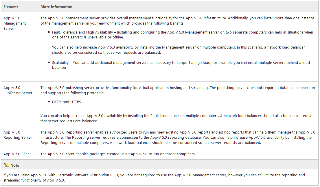
A typical App-V 5.0 implementation consists of the following elements.

App-V2

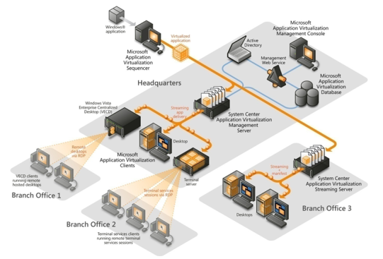
General Diagram of App-V Infrastructure

appv02

Microsoft Application Virtualization 5 Administrator’s Guide

http://technet.microsoft.com/en-us/library/jj713487.aspx

Recommended Deployment Methods

The following list displays the recommended methods for installing the App-V 5.0 server infrastructure:

  • Install the App-V 5.0 server.
  • Install the database, reporting, and management features on separate computers. For more information
  • Use Electronic Software Distribution (ESD).
  • Install all server features on a single computer.

Installing the App-V 5.0 server

I am going to use my following test servers which are VMware Virtual Machines running on VMware vSphere 5.5.

  • 1 x Windows 2012 Server with SQL 2012, IIS 7.5 (Web Server role), Application Server role and Silverlight pre-installed which will also be my App-V 5 Server
  • 1 x Windows 2008 R2 AD server

IIS Settings

  • Common HTTP Features > Static Content
  • Common HTTP Features > Default Document
  • Application Development > ASP.NET
  • Application Development > .NET Extensibility
  • Application Development > ISAPI Extensions
  • Application Development > ISAPI Filters
  • Security > Windows Authentication
  • Security > Request Filtering
  • Management Tools > IIS Management Console

Run the following 2 commands to register ASP.NET with .NET 4 Framework in IIS

  1. “C:\Windows\Microsoft.Net\Framework\v4.0.30319\aspnet_regiis.exe” –ir
  2. “C:\Windows\Microsoft.Net\Framework64\v4.0.30319\aspnet_regiis.exe” -ir

Instructions

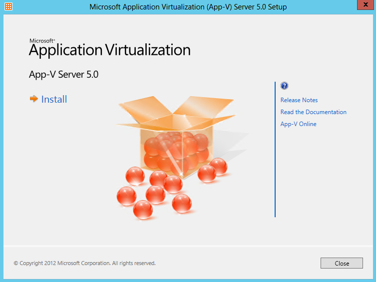
  • Copy the App-V 5.0 server installation files to the computer on which you want to install it on. To start the App-V 5.0 server installation right-click and run appv_server_setup.exe as an administrator. Click Install.

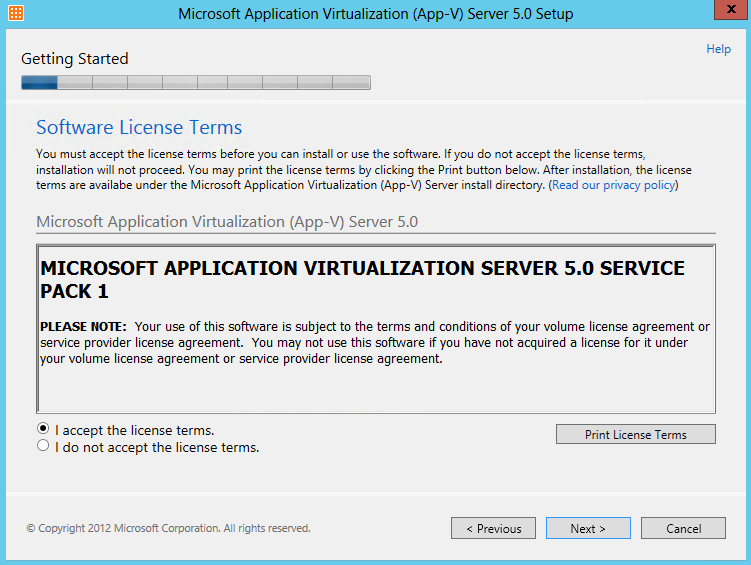
APPV1

  • On the Getting Started page, review the license terms. To accept the license terms select I accept the license terms. Click Next.

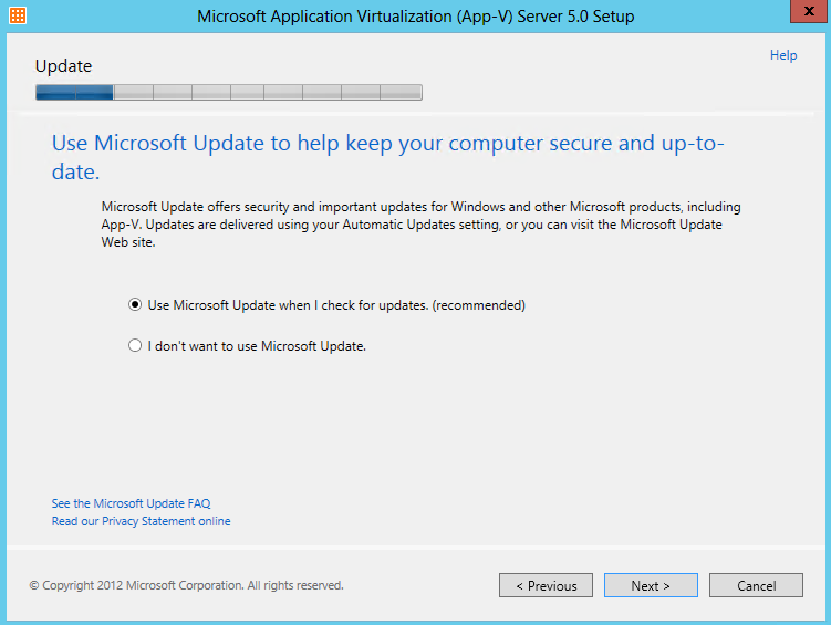
APPV2

  • On the Use Microsoft Update to help keep your computer secure and up-to-date page, to enable Microsoft updates, select Use Microsoft Update when I check for updates (recommended). To disable Microsoft updates, select I don’t want to use Microsoft Update. Click Next

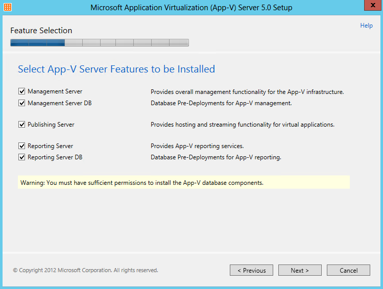
APPV3

  • On the Feature Selection page, select all five of the components

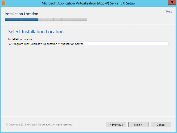
APPV4

  • On the Installation Location page confirm the location where the selected components will be installed. You should accept the default. To change the location, type a new path on the Installation Location line. Click Next.

APPV5

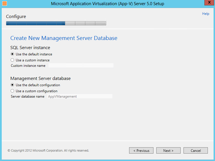
  • On the initial Create New Management Database page configure the Microsoft SQL Server instance and Management Server database
  • If you are using a custom Microsoft SQL Server instance, select Use the custom instance and type the name of the instance. For example, the format should be INSTANCENAME and the installation will assume it is on the local computer.
  • Specifying the server name using the following format ServerName\INSTANCE is not supported.
  • If you are using a custom database name, select Custom configuration. and type the database name.
  • Note: The database name provided must be unique. If an existing database name is specified the installation will fail.

APPV6

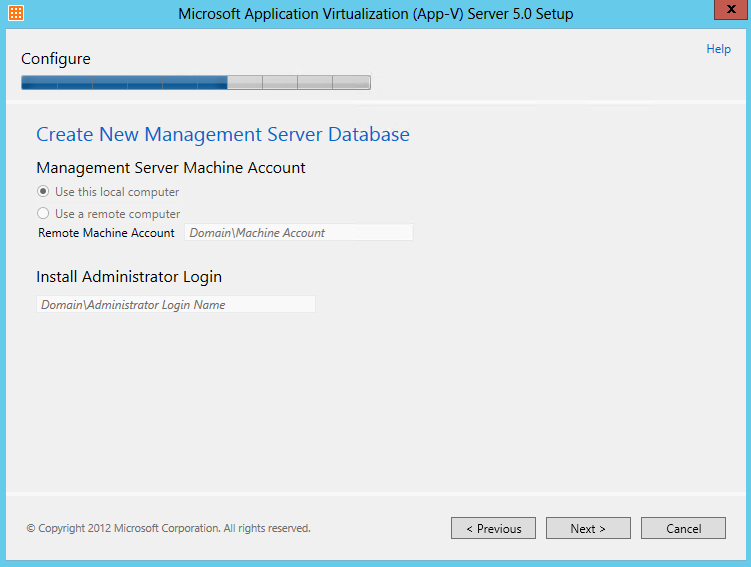
  • On the Configure page, accept the default value: Use this local computer. Click Next.
  • Note: If you are installing the management server and management database side-by-side, options on this page are not available. In this scenario the appropriate options are selected by default and cannot be changed.

APPV7

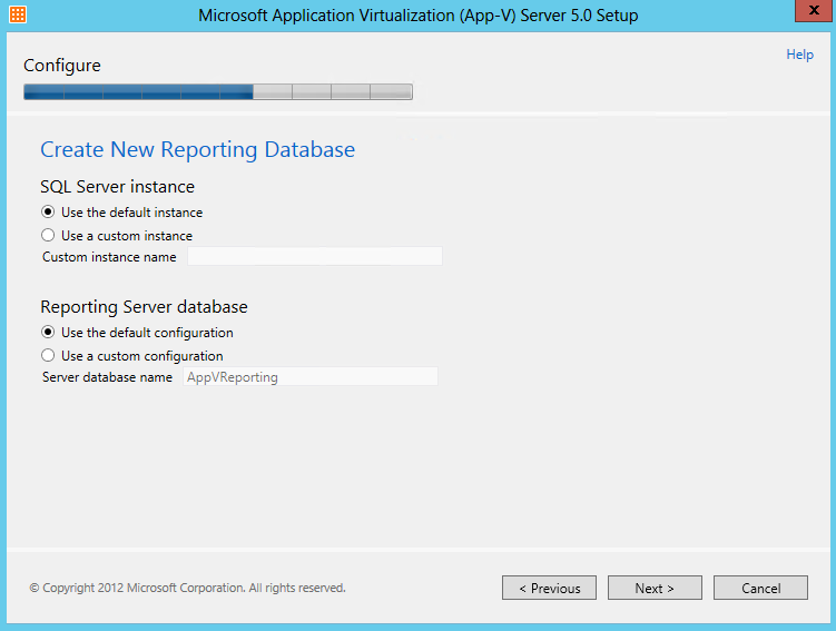
  • On the initial Create New Reporting Database page configure the Microsoft SQL Server instance and Reporting Server database
  • If you are using a custom Microsoft SQL Server instance, select Use the custom instance and type the name of the instance. For example, the format should be INSTANCENAME and the installation will assume it is on the local computer.
  • Note: Specifying the server name using the following format ServerName\ INSTANCE is not supported
  • If you are using a custom database name, select Custom configuration. and type the database name.
  • Note: The database name provided must be unique. If an existing database name is specified the installation will fail.

APPV8

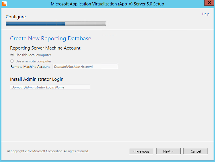
  • On the Configure page, accept the default value: Use this local computer. Click Next
  • Note: If you are installing the reporting server and reporting database side-by-side, options on this page are not available. In this scenario the appropriate options are selected by default and cannot be changed.

APPV9

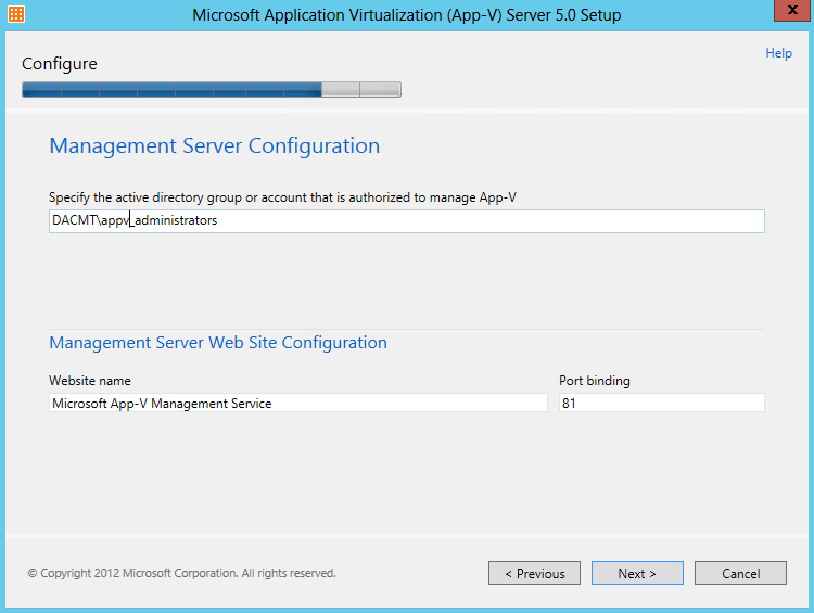
  • On the Configure (Management Server Configuration) page, type the AD Universal Security group with sufficient permissions to manage the App-V 5.0 environment.
  • Note: You can add additional users or groups using the management console after installation. However, global security groups and Active Directory Domain Services (AD DS) distribution groups are not supported. You must use Domain local or Universal groups are required to perform this action.
  • On the Website name line specify the custom name that will be used to run the publishing service. If you do not have a custom name, do not make any changes.
  • For the Port binding, specify a unique port number that will be used by App-V 5.0, for example 12345. You should also ensure that the port specified is not being used by another website like the default IIS website using 80

APPV11

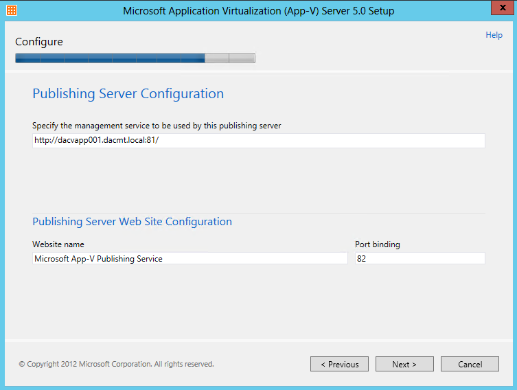
  • On the Configure Publishing Server Configuration page, Specify the URL for the management service. This is the address the publishing server uses to connect to. For example, http://localhost:12345.
  • Specify the Website Name that you want to use for the Publishing Service. Leave the default unchanged if you do not have a custom name.
  • For the Port binding, specify a unique port number that will be used by App-V 5.0, for example 54321. You should also ensure that the port specified is not being used by another website.

appv36

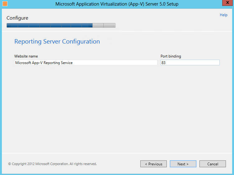
  • On the Reporting Server page, Specify the Website Name that you want to use for the Reporting Service. Leave the default unchanged if you do not have a custom name
  • For the Port binding, specify a unique port number that will be used by App-V 5.0, for example 55555. You should also ensure that the port specified is not being used by another website.

APPV13

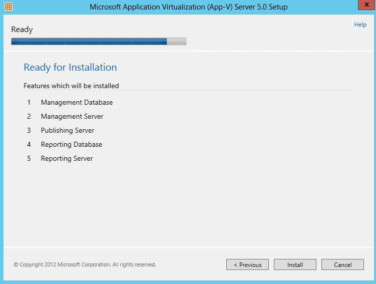
  • On the Ready page, to start the installation, click Install.

APPV14

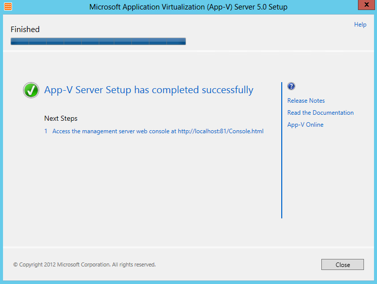
  • On the Finished page, to close the wizard, click Close.
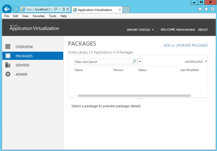
  • To confirm that setup completed successfully, open a web browser, and type the following URL: http://<Management server machine name>:<Management service port number>/Console.html. For example, http://localhost:12345/console.html. If the installation succeeded the App-V 5.0 management console will be displayed without any errors

APPV15

  • And then you will see the following web console

APPV16

The App-V Management Server has a Silverlight®-based management site, which enables administrator configuration of the App-V infrastructure from any computer. By using this site, administrators can add and remove applications, manipulate shortcuts, assign access permissions to users and groups, and create connection groups. The App-V Management Server is the communication conduit between the App-V Web Management Console and the SQL Server data store

Also in a test environment, you may want to change the following registry settings on your publishing server. By default the Publishing Server polls the App-V database for published applications every 10 minutes (600 seconds). This is called a publishing refresh. change the publishing refresh interval to 10 seconds to reduce wait times during publishing. Evaluation of the correct interval for a production environment is outside the scope of this blog.

HKEY_LOCAL_MACHINE\SOFTWARE\Microsoft\AppV\Server\PublishingService PUBLISHING_MGT_SERVER_REFRESH_INTERVAL = 600 (default setting in seconds) PUBLISHING_MGT_SERVER_REFRESH_INTERVAL = 10 (common value used for test environment)

Create and Share a Content folder

The content share is the central library of App-V packages. The content store contains the source files of the packages published by the App-V publishing server.

  1. Open Windows Explorer.
  2. Create a folder on the root of the C: drive named Content.

NOTE: In the production environment, the content folder should not be placed on the same drive as the operating system files as it can affect performance of the system. Ensure the use of a different drive in a production environment.

  1. Browse to C:\, right click the Content folder, go to Properties.
  2. Click the Sharing tab, click Advanced Sharing.
  3. Check Share this folder. Click Permissions
  4. Click Add. Click Object Types. Select Computers. Click OK.
  5. In the Enter the object names to select box, enter the name of the App-V management server. Select Full Control and Click OK.
  6. In the Enter the object names to select box, enter the name of the NETWORK SERVICE account. Click OK. Select Full Control and Click OK.
  7. In the Enter the object names to select box, enter the name of the App-V management server and the AppV Administrators group. Select Full Control and Click OK.
  8. Click OK, Click OK, Click Close

Configure Windows Firewall to Allow Incoming Connections

  1. Open Control Panel, open Windows Firewall
  2. Click Advanced Settings.
  3. Click Inbound Rules, in the actions pane click New Rule…
  4. Select Port, click Next
  5. Select TCP, in the Specific local ports: field, enter your 3 port numbers, click Next
  6.  Click Next, Unselect Private, and Public, click Next
  7. In the Name field, enter AppV Server Connections, click Finish

Next

The next thing to do is to start installing and using the App-V 5 Sequencer and Microsoft Application Virtualization Desktop Client and/or the Microsoft Application Virtualization Remote Desktop Services (RDS) Client which I have covered in another blog. Please see below link

http://www.electricmonk.org.uk/2013/11/28/app-v-5-sequencing/

Windows Server 2012 Scale Out File Server

scales

Scale out File Server

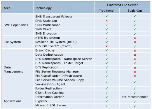
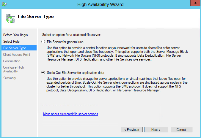
Windows Server 2012 introduces a clustered Scale-Out File Server that provides more reliability by replicating file shares for application data. Scale-Out File Server varies from traditional file-server clustering technologies and isn’t recommended for scenarios with high-volume operations in which opening, closing, or renaming files occurs frequently.

In Windows Server 2012, the following clustered file servers are available:

  • Scale-Out File Server for application data (Scale-Out File Server)   This clustered file server is introduced in Windows Server 2012 and lets you store server application data, such as Hyper-V virtual machine files, on file shares, and obtain a similar level of reliability, availability, manageability, and high performance that you would expect from a storage area network. All file shares are online on all nodes simultaneously. File shares associated with this type of clustered file server are called scale-out file shares. This is sometimes referred to as active-active.
  • File Server for general use   This is the continuation of the clustered file server that has been supported in Windows Server since the introduction of Failover Clustering. This type of clustered file server, and thus all the shares associated with the clustered file server, is online on one node at a time. This is sometimes referred to as active-passive or dual-active. File shares associated with this type of clustered file server are called clustered file shares.

Key benefits provided by Scale-Out File Server in Windows Server 2012 include:

  • Active-Active file shares   All cluster nodes can accept and serve SMB client requests. By making the file share content accessible through all cluster nodes simultaneously, SMB 3.0 clusters and clients cooperate to provide transparent failover to alternative cluster nodes during planned maintenance and unplanned failures with service interruption.
  • Increased bandwidth   The maximum share bandwidth is the total bandwidth of all file server cluster nodes. Unlike previous versions of Windows Server, the total bandwidth is no longer constrained to the bandwidth of a single cluster node, but rather the capability of the backing storage system. You can increase the total bandwidth by adding nodes.
  • CHKDSK with zero downtime   CHKDSK in Windows Server 2012 is significantly enhanced to dramatically shorten the time a file system is offline for repair. Clustered shared volumes (CSVs) in Windows Server 2012 take this one step further and eliminates the offline phase. A CSV File System (CSVFS) can perform CHKDSK without impacting applications with open handles on the file system.
  • Clustered Shared Volume cache    CSVs in Windows Server 2012 introduces support for a read cache, which can significantly improve performance in certain scenarios, such as Virtual Desktop Infrastructure.
  • Simpler management   With Scale-Out File Servers, you create the Scale-Out File Server and then add the necessary CSVs and file shares. It is no longer necessary to create multiple clustered file servers, each with separate cluster disks, and then develop placement policies to ensure activity on each cluster node.

When to use Scale-Out File Server

You should not use Scale-Out File Server if your workload generates a high number of metadata operations, such as opening files, closing files, creating new files, or renaming existing files. A typical information worker would generate a lot of metadata operations. You should use a Scale-Out File Server if you are interested in the scalability and simplicity that it offers and you only require technologies that are supported with Scale-Out File Server. The following table shows the new capabilities in SMB 3.0, common Windows file systems, file server data management and applications, and if they are supported with Scale-Out File Server, or will require a traditional clustered file server:

Scale Out File Server

Review Failover Cluster Requirements

  • Scale-Out File Server is built on top of Failover Clustering so any requirements for Failover Clustering apply to Scale-Out File Server. You should have an understanding of Failover Clustering before deploying Scale-Out File Server
  • The storage configuration must be supported by Failover Clustering before you deploy Scale-Out File Server. You must successfully run the Cluster Validation Wizard before you add Scale-Out File Server.
  • Scale-Out File Server requires the use of Clustered Shared Volumes (CSVs). Since CSVs are not supported with Resilient File System, Scale-Out File Server cannot use Resilient File System.
  • Accessing a continuously available file share as a loopback share is not supported. For example, Microsoft SQL Server or Hyper-V storing their data files on SMB file shares must run on computers that are not a member of the file server cluster for the SMB file shares

Review Storage Requirements

  • Fibre Channel Storage Area Network You can use an existing fibre channel Storage Area Network as the storage subsystem for Scale-Out File Server.
  • iSCSI Storage Area Network You can use an existing iSCSI Storage Area Network as the storage subsystem for Scale-Out File Server.
  • Storage Spaces Storage Spaces is new in Windows Server 2012 and can also be used as the storage subsystem for Scale-Out File Server.
  • Clustered RAID controller A clustered RAID controller is new in Windows Server 2012 and can be used as the storage subsystem for Scale-Out File Server.

Review Networking Requirements

  • Ensure that the network adapter configurations are consistent across all of your nodes in Scale-Out File Server
  • Ensure that the network that includes the CSV redirection traffic has sufficient bandwidth
  • Use DNS dynamic update protocol for the cluster node name and all of the cluster nodes. You should ensure that the cluster node name is registered by using DNS dynamic update protocol. This should include the name of the Scale-Out File Server and the IP addresses of all of the network adapters in every cluster node on the client network.

Deploy Scale Out File Server

To take full advantage of Scale-Out File Server, all servers running the server applications that are using scale-out file shares should be running Windows Server 2012. If the server application is running on Windows Server 2008 or Windows Server 2008 R2, the servers will be able to connect to the scale-out file shares but will not take advantage of any of the new features. If the server application is running Windows Server 2003, the server will get access-denied error when connecting to the scale-out file share.

Prerequisites

  • First of all you will need 2 x Windows Server 2012 Servers built, updated and ready to work with for the Windows Failover Cluster
  • You will need 2 virtual NICs on each Windows 2012 Server. One for the Main Network and one for a Heartbeat network. Modify the provider order so the Main Network always comes first. In Network Connections hold down Alt and F then select Advanced and move your Main Network to the top of the binding order

scaleout40

  • I set up a iSCSI Target Disk from another server for my Scale Out File Server Share. Please see the previous blog for instructions on how to do this
  • I also set up an iSCSI Target from another server for my Quorum Disk. Please see the previous blog for instructions on how to do this
  • * Optional * You can also add 3 basic Virtual disks to your first server which are going to be set up as a Storage Space as detailed in the steps below and leave them as Online, Initialised and Unformatted in Disk Management on your Server. I wanted to see if these could be added into the Failover Cluster Pool as an experiment

scaleout48

  • When you have a default build of your servers before adding any roles and features I would take a snapshot so at least you can go back to where you were when everything was a fresh build and worked!! (Setting this up didn’t work too well for me the first time round and I ended up rebuilding servers and getting cross!)

Procedure

  • Log on to the first server as a member of the local Administrators group.
  • In the QUICK START section, click Add roles and features
  • On the Before you begin page of the Add Roles and Features Wizard, click Next.

Scaleout1

  • On the Select installation type page, click Role-based or feature-based installation, and then click Next.

Scaleout2

  • On the Select destination server page, select the appropriate server, and then click Next. The local server is selected by default.

Scaleout3

  • On the Select server roles page, expand File and Storage Services, expand File Services, and then select the File Server check box. Click Next.

Scaleout4

  • On the Select features page, select the Failover Clustering check box, and then click Next.

Scaleout5

  • Click OK to the pop up box

Scaleout6

  • On the Confirm installation selections page, click Install.

Scaleout7

  • Repeat the steps in this procedure for each server that will be added to the cluster
  • Next Click Tools, and then click Failover Cluster Manager
  • Under the Management heading, click Validate Configuration
  • On the Before You Begin page, click Next

Scaleout8

  • On the Select Servers or a Cluster page, in the Enter name box, type the FQDN of one of the servers that will be part of the cluster, and then click Add. Repeat this step for each server that will be in the cluster

Scaleout9

  • Click OK to see the chosen servers

Scaleout10

  • On the Testing Options page, ensure that the Run all tests (recommended) option is selected, and then click Next.

Scaleout11

  • On the Confirmation page, click Next.

Scaleout12

  • The Validation tests will now run

Scaleout13

  • On the Summary page, ensure that the Create the cluster now using the validated nodes check box is selected, and then click Finish. View the report to make sure you do not need to fix anything before proceeding. The Create Cluster Wizard appears.

Scaleout14

  • On the Before You Begin page, click Next

Scaleout15

  • On the Access Point for Administering the Cluster page, in the Cluster Name box, type a name for the cluster, and choose an IP Address then click Next.

Scaleout16

  • On the Confirmation page, click Next.
  • Untick Add all eligible storage to the cluster

Scaleout17

  • On the Summary page, click Finish.

Scaleout18

  • Right click on Disks in Failover Cluster Manager and select Add Disk

scaleout49

  • The 5GB Disk is my Quorum iSCSI Target Disk
  • The 15GB Disk is my Scale Out File Server iSCSI Target Disk
  • The 3 x 10GB Disks are the 3 basic unformatted virtual disks I added at the start of this procedure to my first server in order to try setting up a storage pool from within the Failover Cluster. Keep these unticked for now
  • You should now see the disks looking like the below

scaleout50

  • You should be now be able to change the Quorum setting from Node Majority to Node and Disk Majority as per the instructions below which is the recommended configuraton for a 2 Node Failover Cluster Server
  • Note the Quorum Disk cannot be a Cluster Shared Volume. Please click Quorum Disk to follow a link to mofe information
  • Right click on the Cluster name in Failover Cluster Manager and select More Actions > Configure Cluster Quorum Settings

scaleout42

  • Select Quorum Configuration Options

scaleout43

  • Select Quorum Witness

scaleout44

  • Configure Storage Witness to be your 5GB Drive

scaleout45

  • Confirmation

scaleout46

  • Summary

scaleout47

  • Next Go to Failover Cluster Manager > Storage > Pools and Select New Pool
  • Note that once physical disks have been added to a pool, they are no longer directly usable by the rest of Windows – they have been virtualized, that is, dedicated to the pool in their entirety

Scaleout21

  • Specify a Name for the Storage Pool and choose the Storage Subsystem that is available to the cluster and click Next
  • Select the Physical Disks for the Storage Pool
  • Note the disks should be Online, Initialised but unallocated. If you don’t see any disks, you need to go into Server Manager and delete the volumes

Scaleout23

  • Confirm Selections

Scaleout24

  • Click Create and you will see the wizard running through the tasks

Scaleout25

  • The next step is to create a Virtual Disk (storage space) that will be associated with a storage pool. In the Failover Cluster Manager, select the storage pool that will be supporting the Virtual Disk. Right-click and choose New Virtual Disk

Scaleout35

  • Select the Storage Pool

Scaleout27

  • Specifiy the Virtual Disk Name

Scaleout28

  • Select the Storage Layout. (Simple or Mirror; Parity is not supported in a Failover Cluster) and click Next

Scaleout29

  • Specifiy the Provisioning Type

Scaleout30

  • Specify the size of your virtual disk – I chose Maximum

Scaleout31

  • Check and Confirm and click Create

Scaleout32

  • View Results and make sure Create a Volume when this wizard closes is ticked

Scaleout33

  • The volume wizard opens

Scaleout34

  • Select the Cluster and your disk

Scaleout36

  • Specify the size of the volume

Scaleout37

  • Choose a drive letter

Scaleout38

  • Select File System Settings

Scaleout39

  • Confirm and Create

Scaleout40

  • You should now see this Virtual Disk Storage space as a drive in Windows
  • Open Failover Cluster Manager.
  • Right-click the cluster, and then click Configure Role.
  • On the Before You Begin page, click Next.
  • On the Select Role page, click File Server, and then click Next.
  • On the File Server Type page, select the Scale-Out File Server for application data option, and then click Next.

Scaleout43

  • On the Client Access Point page, in the Name box, type a NETBIOS name that will be used to access Scale-Out File Server, and then click Next
  • On the Confirmation page, confirm your settings, and then click Next.
  • On the Summary page, click Finish.

Scaleout47PNG

  • Click Start, type Failover Cluster, and then click Failover Cluster Manager
  • Expand the cluster, and then click Roles.
  • Right-click the file server role, and then click Add File Share.
  • On the Select the profile for this share page, click SMB Share – Applications, and then click Next.
  • On the Select the server and path for this share page, click the cluster shared volume, and then click Next.
  • On the Specify share name page, in the Share name box, type a name, and then click Next.
  • On the Configure share settings page, ensure that the Enable continuous availability check box is selected, and then click Next.
  • On the Specify permissions to control access page, click Customize permissions, grant the following permissions, and then click Next:
  • If you are using this Scale-Out File Server file share for Hyper-V, all Hyper-V computer accounts, the SYSTEM account, and all Hyper-V administrators must be granted full control on the share and the file system.
  • If you are using Scale-Out File Server on Microsoft SQL Server, the SQL Server service account must be granted full control on the share and the file system
  • On the Confirm selections page, click Create.
  • On the View results page, click Close
  • Note: You should not use access-based enumeration on file shares for Scale-Out File Server because of the increased metadata traffic that is generated on the coordinator node.

Useful Links

http://technet.microsoft.com/en-us/library/jj612868.aspx

http://support.microsoft.com/kb/2813005/en-us

Storage Spaces in Windows Server 2012

Storage

What are Storage Spaces?

A technology in Windows and Windows Server that enables you to virtualize storage by grouping industry-standard disks into storage pools, and then create virtual disks called storage spaces from the available capacity in the storage pools

Storage Spaces enables cost-effective, highly available, scalable, and flexible storage solutions for business-critical (virtual or physical) deployments. Storage Spaces delivers sophisticated storage virtualization capabilities, which empower customers to use industry-standard storage for single computer and scalable multi-node deployments. It is appropriate for a wide range of customers, including enterprise and cloud hosting companies, which use Windows Server for highly available storage that can cost-effectively grow with demand.

With Storage Spaces the Windows storage stack has been fundamentally enhanced to incorporate two new abstractions:

  • Storage pools. A collection of physical disks that enable you to aggregate disks, expand capacity in a flexible manner, and delegate administration.
  • Storage spaces. Virtual disks created from free space in a storage pool. Storage spaces have such attributes as resiliency level, storage tiers, fixed provisioning, and precise administrative control.

Storage Spaces is manageable through the Windows Storage Management API in Windows Management Instrumentation (WMI) and Windows PowerShell, and through the File and Storage Services role in Server Manager. Storage Spaces is completely integrated with failover clustering for high availability, and it is integrated with CSV for scale-out deployments

Important functionality

Storage Spaces includes the following features:

  • Storage pools.

Storage pools are the fundamental building blocks for Storage Spaces. Storage administrators are already familiar with this concept, obviating the need to learn a new model. They can flexibly create storage pools based on the needs of the deployment. For example, given a set of physical disks, an administrator can create one pool (by using all the available physical disks) or multiple pools (by dividing the physical disks as required). Furthermore, to maximize the value from storage hardware, the administrator can combine hard disks and solid-state drives (SSDs) in the same pool, using storage tiers to move frequently accessed portions of files to SSD storage, and using write-back caches to buffer small random writes to SSD storage. Pools can be expanded dynamically by simply adding additional drives, thereby seamlessly scaling to cope with unceasing data growth.

  • Resilient storage.

Storage Spaces provides three storage layouts (also known as resiliency types):

  • Mirror. Data is duplicated on two or three physical disks, increasing reliability, but reducing capacity. This storage layout requires at least two disks to protect you from a single disk failure, or at least five disks to protect you from two simultaneous disk failures.
  • Parity. Data and parity information are striped across physical disks, increasing reliability, but somewhat reducing capacity. This storage layout requires at least three disks to protect you from a single disk failure and at least seven disks to protect you from two disk failures.
  • Simple (no resiliency). Data is striped across physical disks, maximizing capacity and increasing throughput, but decreasing reliability. This storage layout requires at least one disk and does not protect you from a disk failure.

Additionally, Storage Spaces can automatically rebuild mirror and parity spaces in which a disk fails by using dedicated disks that are reserved for replacing failed disks (hot spares), or more rapidly by using spare capacity on other drives in the pool. Storage Spaces also includes background scrubbing and intelligent error correction to allow continuous service availability despite storage component failures. In the event of a power failure or cluster failover, the integrity of data is preserved so that recovery happens quickly and does not result in data loss.

  • Continuous availability.

Storage Spaces is fully integrated with failover clustering, which allows it to deliver continuously available service deployments. One or more pools can be clustered across multiple nodes within a single cluster. Storage spaces can then be instantiated on individual nodes, and the storage will seamlessly fail over to a different node when necessary (in response to failure conditions or due to load balancing). Integration with CSVs permits scale-out access to data.

  • Storage tiers.

Storage Spaces in Windows Server 2012 R2 Preview combines the best attributes of SSDs and hard disk drives (HDDs) by enabling the creation of virtual disks composed of two tiers of storage – an SSD tier for frequently accessed data, and a HDD tier for less-frequently accessed data. Storage Spaces transparently moves data at a sub-file level between the two tiers based on how frequently data is accessed. As a result, storage tiers can dramatically increase performance for the most used (“hot”) data by moving it to SSD storage, without sacrificing the ability to store large quantities of data on inexpensive HDDs.

  • Write-back cache.

Storage Spaces in Windows Server 2012 R2 Preview supports creating a write-back cache that uses a small amount of space on existing SSDs in the pool to buffer small random writes. Random writes, which often dominate common enterprise workloads, are directed to SSDs and later are written to HDDs.

  • Operational simplicity.

The Windows Storage Management API, WMI, and Windows PowerShell permit full scripting and remote management. Storage Spaces can also be easily managed through the File and Storage Services role in Server Manager. Storage Spaces also provides notifications when the amount of available capacity in a storage pool hits a configurable threshold.

  • Multitenancy.

Administration of storage pools can be controlled through access control lists (ACLs) and delegated on a per-pool basis, thereby supporting hosting scenarios that require tenant isolation. Storage Spaces follows the familiar Windows security model; therefore, it can be fully integrated with Active Directory Domain Services.

Requirements

Storage Spaces has the following requirements:

  • Windows Server 2012 R2 Preview, Windows Server 2012, Windows 8.1 Preview, or Windows 8.
  • Serial ATA (SATA) or Serial Attached SCSI (SAS) connected disks, optionally in a just-a-bunch-of-disks (JBOD) enclosure. RAID adapters, if used, must have all RAID functionality disabled and must not obscure any attached devices, including enclosure services provided by an attached JBOD
  • Consumers can use USB drives with Storage Spaces, though USB 3 drives are recommended to ensure a high level of performance. USB 2 drives will decrease performance – a single USB 2 hard drive can saturate the bandwidth available on the shared USB bus, limiting performance when multiple drives are attached to the same USB 2 controller. When using USB 2 drives, plug them directly into different USB controllers on your computer, do not use USB hubs, and add USB 2 drives to a separate storage pool used only for storage spaces that do not require a high level of performance
  • For shared-storage deployments on failover clusters: Two or more servers running Windows Server 2012 R2 Preview or Windows Server 2012, Requirements as specified for failover clustering and Cluster Shared Volumes (CSV) and SAS connected JBODs that comply with Windows Certification requirements

What are the recommended configuration limits?

In Windows Server 2012, the following are the recommended configuration limits:

  • Up to 160 physical disks in a storage pool; you can, however, have multiple pools of 160 disks.
  • Up to 480 TB of capacity in a single storage pool.
  • Up to 128 storage spaces in a single storage pool.
  • In a clustered configuration, up to four storage pools per cluster.

FAQs

http://social.technet.microsoft.com/wiki/contents/articles/11382.storage-spaces-frequently-asked-questions-faq.aspx

Deploying Storage Spaces

In this example I will create a Storage Space from a Resource Pool containing 3 Disks

Storage Spaces4

Procedure 

  • Go to Server Manager > File and Storage Services > Storage Pools
  • Click Tasks and Select New Storage Pool
  • Note that once physical disks have been added to a pool, they are no longer directly usable by the rest of Windows – they have been virtualized, that is, dedicated to the pool in their entirety

Scaleout21

  • Specify a Name for the Storage Pool and choose the Storage Subsystem that is available

storagespaces3

  • Select the Physical Disks for the Storage PooL
  • Note the disks should be Online, Initialised but unallocated. If you don’t see any disks, you need to go into Server Manager and delete the volumes

Scaleout23

  • Confirm Selections

Scaleout24

  • Click Create and you will see the wizard running through the tasks

Scaleout25

  • The next step is to create a Virtual Disk (storage space) that will be associated with a storage pool. In the Failover Cluster Manager, select the storage pool that will be supporting the Virtual Disk. Right-click and choose New Virtual Disk

Scaleout35

  • Select the Storage Pool

Scaleout27

  • Specifiy the Virtual Disk Name

Scaleout28

  • Select the Storage Layout. (Simple or Mirror; Parity is not supported in a Failover Cluster) and click Next

Scaleout29

  • Specifiy the Provisioning Type

Scaleout30

  • Specify the size of your virtual disk – I chose Maximum

Scaleout31

  • Check and Confirm and click Create

Scaleout32

  • View Results and make sure Create a Volume when this wizard closes is ticked

Scaleout33

  • The volume wizard opens

Scaleout34

  • Select the Cluster and your disk

Scaleout36

  • Specify the size of the volume

Scaleout37

  • Choose a drive letter

Scaleout38

  • Select File System Settings

Scaleout39

  • Confirm and Create

Scaleout40

  • You should now see this Virtual Disk Storage space as a drive in Windows


Cluster Shared Volumes in Windows Server 2012

Cluster

What are Cluster Shared Volumes?

Cluster Shared Volumes (CSVs) in a Windows Server 2012 failover cluster allow multiple nodes in the cluster to simultaneously have read-write access to the same LUN (disk) that is provisioned as an NTFS volume. With CSVs, clustered roles can fail over quickly from one node to another node without requiring a change in drive ownership, or dismounting and remounting a volume. CSVs also help simplify managing a potentially large number of LUNs in a failover cluster.

CSVs provide a general-purpose, clustered file system in Windows Server 2012, which is layered above NTFS. They are not restricted to specific clustered workloads. (In Windows Server 2008 R2, CSVs only supported the Hyper-V workload.) CSV applications include:

  • Clustered virtual hard disk (VHD) files for clustered Hyper-V virtual machines
  • Scale-out file shares to store application data for the Scale-Out File Server role. Examples of the application data for this role include Hyper-V virtual machine files and Microsoft SQL Server data

Other Details

  • At this time, CSVs do not support the Microsoft SQL Server clustered workload.
  • External authentication dependencies for CSVs have been removed
  • CSVs support the functional improvements in chkdsk
  • CSVs interoperate with antivirus and backup applications
  • CSVs are also now integrated with general storage features such as Bitlocker and Storage Spaces
  • Cluster Share Volumes (CSVs), system volumes, dynamic disks, and Resilient File System (ReFS) are not eligible for data deduplication

Benefits of using Cluster Shared Volumes in a failover cluster

Cluster Shared Volumes provides the following benefits in a failover cluster:

  • The configuration of clustered virtual machines is much simpler than before.
  • You can reduce the number of LUNs (disks) required for your virtual machines, instead of having to manage one LUN per virtual machine, which was previously the recommended configuration (because the LUN was the unit of failover). Many virtual machines can use a single LUN and can fail over without causing the other virtual machines on the same LUN to also fail over.
  • You can make better use of disk space, because you do not need to place each Virtual Hard Disk (VHD) file on a separate disk with extra free space set aside just for that VHD file. Instead, the free space on a Cluster Shared Volume can be used by any VHD file on that volume.
  • You can more easily track the paths to VHD files and other files used by virtual machines. You can specify the path names, instead of identifying disks by drive letters (limited to the number of letters in the alphabet) or identifiers called GUIDs (which are hard to use and remember). With Cluster Shared Volumes, the path appears to be on the system drive of the node, under the \ClusterStorage folder. However, this path is the same when viewed from any node in the cluster.
  • If you use a few Cluster Shared Volumes to create a configuration that supports many clustered virtual machines, you can perform validation more quickly than you could with a configuration that uses many LUNs to support many clustered virtual machines. With fewer LUNs, validation runs more quickly. (You perform validation by running the Validate a Configuration Wizard in the snap-in for failover clusters.)
  • There are no special hardware requirements beyond what is already required for storage in a failover cluster (although Cluster Shared Volumes require NTFS).
  • Resiliency is increased, because the cluster can respond correctly even if connectivity between one node and the SAN is interrupted, or part of a network is down. The cluster will re-route the Cluster Shared Volumes communication through an intact part of the SAN or network.

How to Configure a Clustered Storage Space in Windows Server 2012

Prerequisites

  • A minimum of three physical drives, with at least 4 gigabytes (GB) capacity each, are required to create a storage pool in a Failover Cluster.
  • The clustered storage pool MUST be comprised of Serial Attached SCSI (SAS) connected physical disks. Layering any form of storage subsystem, whether an internal RAID card or an external RAID box, regardless of being directly connected or connected via a storage fabric, is not supported.
  • All physical disks used to create a clustered pool must pass the Failover Cluster validation tests.
  • To run cluster validation tests: Open the Failover Cluster Manager interface (cluadmin.msc) and select the Validate Cluster options
  • Clustered storage spaces must use fixed provisioning.
  • Simple and mirror storage spaces are supported for use in Failover Cluster. Parity Spaces are not supported.
  • The physical disks used for a clustered pool must be dedicated to the pool. Boot disks should not be added to a clustered pool nor should a physical disk be shared among multiple clustered pools.
  • Storage spaces formatted with ReFS cannot be added to the Cluster Shared Volume (CSV)

Procedure

  • Go to Server Manager > File and Storage Services > Storage Pools and Select New Pool
  • Note that once physical disks have been added to a pool, they are no longer directly usable by the rest of Windows – they have been virtualized, that is, dedicated to the pool in their entirety

Scaleout21

  • Specify a Name for the Storage Pool and choose the Storage Subsystem that is available to the cluster and click Next
  • Select the Physical Disks for the Storage Pool
  • Note the disks should be Online, Initialised but unallocated. If you don’t see any disks, you need to go into Server Manager and delete the volumes

Scaleout23

  • Confirm Selections

Scaleout24

  • Click Create and you will see the wizard running through the tasks

Scaleout25

  • The next step is to create a Virtual Disk (storage space) that will be associated with a storage pool. In the Failover Cluster Manager, select the storage pool that will be supporting the Virtual Disk. Right-click and choose New Virtual Disk

Scaleout35

  • Select the Storage Pool

Scaleout27

  • Specifiy the Virtual Disk Name

Scaleout28

  • Select the Storage Layout. (Simple or Mirror; Parity is not supported in a Failover Cluster) and click Next

Scaleout29

  • Specifiy the Provisioning Type

Scaleout30

  • Specify the size of your virtual disk – I chose Maximum

Scaleout31

  • Check and Confirm and click Create

Scaleout32

  • View Results and make sure Create a Volume when this wizard closes is ticked

Scaleout33

  • The volume wizard opens

Scaleout34

  • Select the Cluster and your disk

Scaleout36

  • Specify the size of the volume

Scaleout37

  • Choose a drive letter

Scaleout38

  • Select File System Settings

Scaleout39

  • Confirm and Create

Scaleout40

  • You should now see this Virtual Disk Storage space as a drive in Windows
  • In Failover Cluster Manager, expand ClusterName, expand Storage, and then click Disks
  • Right-click a cluster disk, and then click Add to Cluster Shared Volumes. The Assigned To column changes to Cluster Shared Volume.

cluster


Installing and Configuring iSCSI Target Server on Windows Server 2012

iscsi

What is iSCSI Target Server?

iSCSI Target allows your Windows Server to share block storage remotely. iSCSI leverages the Ethernet network and does not require any specialized hardware. There is a brand new UI integrated with Server manager, along with 20+ cmdlets for easy management.

iSCSI Terms

  • iSCSI:

An industry standard protocol allow sharing block storage over the Ethernet. The server shares the storage is called iSCSI Target. The server (machine) consumes the storage is called iSCSI initiator. Typically, the iSCSI initiator is an application server. For example, iSCSI Target provides storage to a SQL server, the SQL server will be the iSCSI initiator in this deployment.

  • Target:

It is an object which allows the iSCSI initiator to make a connection. The Target keeps track of the initiators which are allowed to be connected to it. The Target also keeps track of the iSCSI virtual disks which are associated with it. Once the initiator establishes the connection to the Target, all the iSCSI virtual disks associated with the Target will be accessible by the initiator.

  • iSCSI Target Server:

The server runs the iSCSI Target. It is also the iSCSI Target role name in Windows Server 2012.

  • iSCSI virtual disk:

It also referred to as iSCSI LUN. It is the object which can be mounted by the iSCSI initiator. The iSCSI virtual disk is backed by the VHD file.

  • iSCSI connection:

iSCSI initiator makes a connection to the iSCSI Target by logging on to a Target. There could be multiple Targets on the iSCSI Target Server, each Target can be accessed by a defined list of initiators. Multiple initiators can make connections to the same Target. However, this type of configuration is only supported with clustering. Because when multiple initiators connects to the same Target, all the initiators can read/write to the same set of iSCSI virtual disks, if there is no clustering (or equivalent process) to govern the disk access, corruption will occur. With Clustering, only one machine is allowed to access the iSCSI virtual disk at one time.

  • IQN:

It is a unique identifier of the Target or Initiator. The Target IQN is shown when it is created on the Server. The initiator IQN can be found by typing a simple “iscsicli” cmd in the command window.

  • Loopback:

There are cases where you want to run the initiator and Target on the same machine; it is referred as “loopback”. In Windows Server 2012, it is a supported configuration. In loopback configuration, you can provide the local machine name to the initiator for discovery, and it will list all the Targets which the initiator can connect to. Once connected, the iSCSI virtual disk will be presented to the local machine as a new disk mounted. There will be performance impact to the IO, since it will travel through the iSCSI initiator and Target software stack when comparing to other local I/Os. One use case of this configuration is to have initiators writing data to the iSCSI virtual disk, then mount those disks on the Target server (using loopback) to check the data in read mode.

Instructions

The aim of this particular blog is to configure an iSCSI Target Disk which my Windows Server 2012 Failover Cluster can use as its Quorum Disk so we will be configuring a 5GB Quorum Disk which we will then present to the Failover Cluster Servers

  • Open Server Manager and click Add Roles and Features

ISCSI1

  • Choose Role based or Feature based installation

iSCSI2

  • Select Destination Server

iSCSI3

  • Select Server Roles > File and Storage Services > File and iSCSI Services > iSCSI Target Server

iSCSI4

  • Add Features that are required for iSCSI Target Server (None ticked here)

iSCSI5

  • Confirm Installation Selections

iSCSI6

  •  To complete iSCSI target server the configuration go to Server Manager , click File and Storage Services > iSCSI
  • Go to iSCSI Virtual disks and click “Launch the New Virtual Disk wizard to create a virtual disk” and walk through the Virtual Disks and targets creation
  • Select an iSCSI virtual disk location

iSCSI7

  • Specify iSCSI virtual disk name

iSCSI8

  • Specify iSCSI virtual disk size

iSCSI9

  • Assign iSCSI Target

iSCSI10

  • Specify Target Name. Underscores are not allowed but it will change them for you

iSCSI12

  • Specify Access Servers

iSCSI14

  • Select a method to identify the initiator

iSCSI13

  • Click Browse and type in the name of the servers which will need to access this virtual disk
  • I have added my 2 Windows Failover Cluster VMs which are called dacvsof001 and dacvsof002

iSCSI15

  • Enable Authentication

iSCSI16

  • Confirm Selections

iSCSI17

  • View Results

iSCSI18

  • Next we need to go to the first Failover Cluster Server dacvsof001 and add the disk
  • On dacvsof001, open Server Manager click Tools and select iSCSI Initiator. When you select this, you will get the following message. Click Yes

iSCSI19

  • Type the Target Server address in which is the server you created the Virtual Disk on and click Quick Connect

iSCSI20

  • You will the Target listed which is available for connection

iSCSI21

  • Click Done
  • Now open Disk Management to make sure that the disk is presented correctly

iSCSI22

  • Right click on this and select Online
  • Right click again and select Initialise
  • Create new Volume. I used Q for Quorum Disk

iSCSI23

  • Now go to the second Windows Failover Cluster Server and do exactly the same thing
  • Leave this disk online and initialised but not given a letter