Archive for Objective 1 Storage

Understand and apply VMFS resignaturing

VMFS LUN UUID

Every VMFS based LUN is assigned a Universally Unique Identifier (UUID). The UUID is stored in the metadata of your file system called a superblock and is a unique hexadecimal number generated by VMware.

When a LUN is copied or a replication made of an original LUN, the copied LUN ends up being absolutely identical to the original LUN including having the same UUID. This means the newly copied LUN must be resignatured before it is mounted. ESXi can determine whether a LUN contains a VMFS copy and does not mount it automatically

VMFS resignaturing does not apply to NFS Datastores

VMFS Resignaturing

  1. Creating a new signature for a drive is irreversible
  2. A datastore with extents (Spanned Datastore) may only be resignatured if all extents are online
  3. The VMs that use a datastore that was resignatured must be reassociated with the disk in their respective configuration files. The VMs must also be re-registered within vCenter
  4. The procedure is fault tolerant. If interrupted, it will continue later

Resignature a datastore using vSphere Client

  1. Log into vCenter using vClient
  2. Click Configuration > Storage
  3. Click Add Storage in the right window frame
  4. Select Disk/LUN and click Next
  5. Select the device to add and click Next
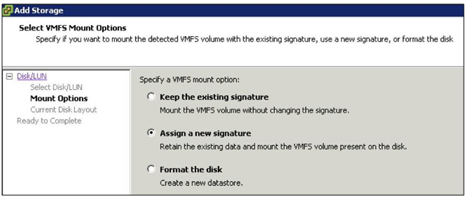
  6. You then have 3 options

sig

  1. Keep the existing signature: This option will leave the VMFS partition unchanged
  2. Assign a new signature: This option will delete the existing disk signature and replace it with a new one. This option must be selected if the original VMFS volume is still mounted (It isn’t possible to have two separate volumes with the same UUID mounted simultaneously)
  3. Format the disk: This option is the same as creating a new VMFS volume on an empty LUN
  4. Select Assign new signature and click Next
  5. Review your changes and then click Finish

Applying resignaturing using ESXCLI

  • SSH into a host using Putty or login into vMA
  • Type esxcli storage vmfs snapshot list. This will list the copies
  • esxcli storage vmfs snapshot mount -l (VolumeName)
  • esxcli storage vmfs snapshot resignature -l (VolumeName)

Troubleshooting

As of ESXi/ESX 4.0, it is no longer necessary to handle snapshot LUNs via the CLI. Resignature and Force-Mount operations have full GUI support and vCenter Server does VMFS rescans on all hosts after a resignature operation.

Snapshot LUNs issue is caused when the ESXi/ESX host cannot confirm the identity of the LUN with what it expects to see in the VMFS metadata. This can be caused by replaced SAN hardware, firmware upgrades, SAN replication, DR tests, and some HBA firmware upgrades. Some ESXi/ESX host upgrades from 3.5 to 4.x (due to the change in naming convention from mpx to naa) have also been known to cause this, but this is a rare occurrence. For more/related information, see Managing Duplicate VMFS Datastores in the vSphere Storage Guide for ESXi 5.x.

Force mounting a VMFS datastore may fail if:

  1. Multiple ESXi/ESX 4.x and 5.0 hosts are managed by the same vCenter Server and these hosts are in the same datacenter.
  2. A snapshot LUN containing a VMFS datastore is presented to all these ESXi/ESX hosts.
  3. One of these ESXi/ESX hosts has force mounted the VMFS datastore that resides on this snapshot LUN.
  4. A second ESXi/ESX host is attempting to do an operation at the same time.

When one ESXi/ESX host force mounts a VMFS datastore residing on a LUN which has been detected as a snapshot, an object is added to the datacenter grouping in the vCenter Server database to represent that datastore.

When a second ESXi/ESX host attempts to do the same operation on the same VMFS datastore, the operation fails because an object already exists within the same datacenter grouping in the vCenter Server database.

Since an object already exists, vCenter Server does not allow mounting the datastore on any other ESXi/ESX host residing in that same datacenter.

ESXCLI Commands for troubleshooting

Snapshot1

Useful YouTube Link

http://www.youtube.com/watch?feature=player_embedded&v=CFJTjbPGlY4

VMware Article Link

http://kb.vmware.com/selfservice/microsites/search.do?language=en_US&cmd=displayKC&externalId=1011387

Apply VMware storage Best Practices

best-practice

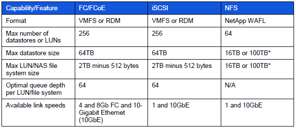
Datastore supported features

ds

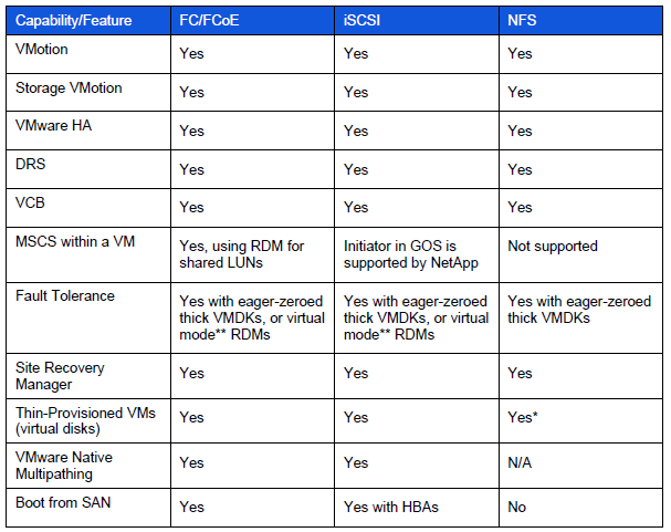
VMware supported storage related functionality

ds3

Storage Best Practices

  • Always use the Vendors recommendations whether it be EMC, NetApp or HP etc
  • Document all configurations
  • In a well-planned virtual infrastructure implementation, a descriptive naming convention aids in identification and mapping through the multiple layers of virtualization from storage to the virtual machines. A simple and efficient naming convention also facilitates configuration of replication and disaster recovery processes.
  • Make sure your SAN fabric is redundant (Multi Path I/O)
  • Separate networks for storage array management and storage I/O. This concept applies to all storage protocols but is very pertinent to Ethernet-based deployments (NFS, iSCSI, FCoE). The separation can be physical (subnets) or logical (VLANs), but must exist.
  • If leveraging an IP-based storage protocol I/O (NFS or iSCSI), you might require more than a single IP address for the storage target. The determination is based on the capabilities of your networking hardware.
  • With IP-based storage protocols (NFS and iSCSI) you channel multiple Ethernet ports together. NetApp refers to this function as a VIF. It is recommended that you create LACP VIFs over multimode VIFs whenever possible.
  • Use CAT 6 cabling rather than CAT 5
  • Enable Flow-Control (should be set to receive on switches and
    transmit on iSCSI targets)
  • Enable spanning tree protocol with either RSTP or portfast
    enabled. Spanning Tree Protocol (STP) is a network protocol that makes sure of a loop-free topology for any bridged LAN
  • Configure jumbo frames end-to-end. 9000 rather than 1500 MTU
  • Ensure Ethernet switches have the proper amount of port
    buffers and other internals to support iSCSI and NFS traffic
    optimally
  • Use Link Aggregation for NFS
  • Maximum of 2 TCP sessions per Datastore for NFS (1 Control Session and 1 Data Session)
  • Ensure that each HBA is zoned correctly to both SPs if using FC
  • Create RAID LUNs according to the Applications vendors recommendation
  • Use Tiered storage to separate High Performance VMs from Lower performing VMs
  • Choose Virtual Disk formats as required. Eager Zeroed, Thick and Thin etc
  • Choose RDMs or VMFS formatted Datastores dependent on supportability and Aplication vendor and virtualisation vendor recommendation
  • Utilise VAAI (vStorage APIs for Array Integration) Supported by vSphere 5
  • No more than 15 VMs per Datastore
  • Extents are not generally recommended
  • Use De-duplication if you have the option. This will manage storage and maintain one copy of a file on the system
  • Choose the fastest storage ethernet or FC adaptor (Dependent on cost/budget etc)
  • Enable Storage I/O Control
  • VMware highly recommend that customers implement “single-initiator, multiple storage target” zones. This design offers an ideal balance of simplicity and availability with FC and FCoE deployments.
  • Whenever possible, it is recommended that you configure storage networks as a single network that does not route. This model helps to make sure of performance and provides a layer of data security.
  • Each VM creates a swap or pagefile that is typically 1.5 to 2 times the size of the amount of memory configured for each VM. Because this data is transient in nature, we can save a fair amount of storage and/or bandwidth capacity by removing this data from the datastore, which contains the production data. In order to accomplish this design, the VM’s swap or pagefile must be relocated to a second virtual disk stored in a separate datastore
  • It is the recommendation of NetApp, VMware, other storage vendors, and VMware partners that the partitions of VMs and the partitions of VMFS datastores are to be aligned to the blocks of the underlying storage array. You can find more information around VMFS and GOS file system alignment in the following documents from various vendors
  • Failure to align the file systems results in a significant increase in storage array I/O in order to meet the I/O requirements of the hosted VMs

vCenter Server Storage Filters

filter_data

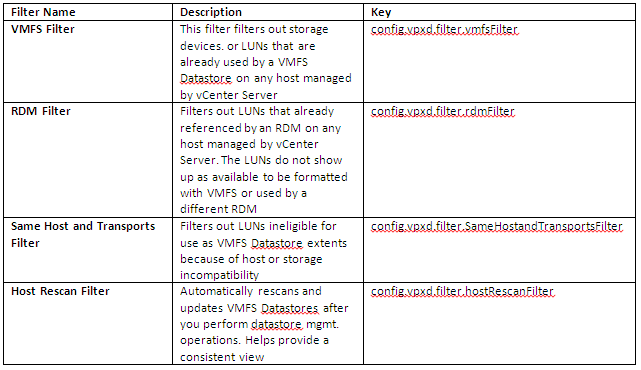
What are the vCenter Server Storage Filters?

They are filters provided by vCenter to help avoid device corruption or performance issues which could arise as a result of using an unsupported storage device.

Storage Filter Chart

filter

How to access the Storage Filters

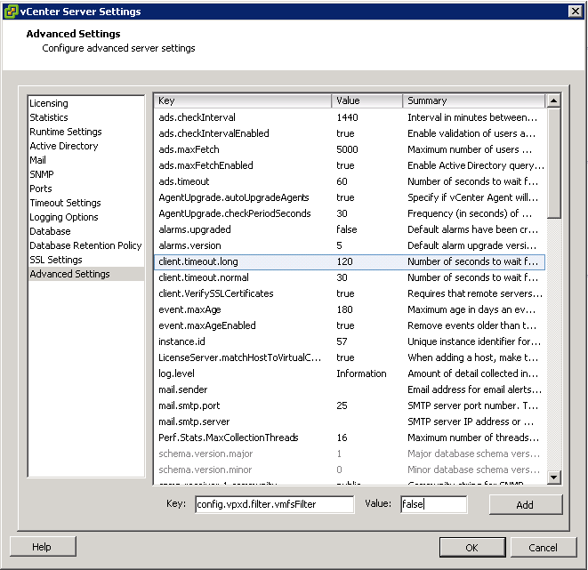
If you want to change the filter behaviour, please do the following

  • Log into the vSphere client
  • Select Administration > vCenter Server Settings
  • Select Advanced Settings
  • In the Key box, type the key you want to change
  • To disable the key, type False
  • Click Add
  • Click OK
  • Note the pic below is from vSphere 4.1

advsettings

Determine appropriate RAID levels for various Virtual Machine workloads

storage

Choosing a RAID level for a particular machine workload relies on the consideration of a lot of different factors if you want your machine/machines to run at their maximum potential and with Best Practices in mind

Other factors

  • Manufacturers Disk IOPs values
  • Type of Disk. E.g SATA, SAS, NSATA, SSD and FC
  • Speed of Disk. E.g 15K or 10K RPM etc
  • To ensure a stable and consistent I/O response, maximize the number of VM storage disks available. This strategy enables you to spread disk reads and writes across multiple disks at once, which reduces the strain on a smaller number of drives and allows for greater throughput and response times.
  • Controller and transport speeds affect VM performance
  • Disk Cost.
  • Some vendors have their own proprietary RAID Level. E.g Netapp RAID DP
  • The RAID level you choose for your LUN configuration can further optimize VM performance. But there’s a cost-vs-functionality component to consider. RAID 0+1 and 1+0 will give you the best virtual machine performance but will come at a higher cost, because they utilize only  50% of all allocated disks
  • RAID 5 will give you more storage for your money, but it requires you to write parity bits across drives. However slower SANs or local VM storage can create a resource deficit which can create bottlenecks
  • Cache Sizes
  • Connectivity. E.g. ISCSI, FC or FCOE. Fibre Channel and iSCSI are the most common transports and within these transports, there are different speeds. E.g. 1/10 GB iSCSI and 4/8 GB FC
  • Thin provisioning. This will take up less space on the SAN but create extra I/O utilisation due to the zeroing of blocks on write
  • De-deuplication. This does not necessarily improve storage performance but it stops duplicate data on storage which can save a great deal of money
  • Predictive Scheme. Create several LUNs with varying storage characteristics
  • Adaptive Scheme. Create large datastores and place VMs on and monitor performance

Please see the following links for general information on RAID and IOPS

http://www.electricmonk.org.uk/2013/01/03/raid-levels/

http://www.electricmonk.org.uk/2012/01/30/iops/


Determine requirements for and configure NPIV

Going-way-too-fast-coloring-page.png

What does NPIV stand for?

(N_Port ID Virtualization)

What is an N_Port?

An N_Port is an end node port on the Fibre Channel fabric. This could be an HBA (Host Bus Adapter) in a server or a target port on a storage array.

What is NPIV?

N_Port ID Virtualization or NPIV is a Fibre Channel facility allowing multiple N_Port IDs to share a single physical N_Port. This allows multiple Fibre Channel initiators to occupy a single physical port, easing hardware requirements in Storage Area Network design, especially where virtual SANs are called for. NPIV is defined by the Technical Committee T11 in the Fibre Channel – Link Services (FC-LS) specification

NPIV  allows a single host bus adaptor (HBA) or target port on a storage array to register multiple World Wide Port Names (WWPNs) and N_Port identification numbers.  This allows each virtual server to present a different world wide name to the storage area network (SAN), which in turn means that each virtual server will see its own storage — but no other virtual server’s storage

How NPIV-Based LUN Access Works

NPIV enables a single FC HBA port to register several unique WWNs with the fabric, each of which can be assigned to an individual virtual machine.

SAN objects, such as switches, HBAs, storage devices, or virtual machines can be assigned World Wide Name (WWN) identifiers. WWNs uniquely identify such objects in the Fibre Channel fabric. When virtual machines have WWN assignments, they use them for all RDM traffic, so the LUNs pointed to by any of the RDMs on the virtual machine must not be masked against its WWNs. When virtual machines do not have WWN assignments, they access storage LUNs with the WWNs of their host’s physical HBAs. By using NPIV, however, a SAN administrator can monitor and route storage access on a per virtual machine basis. The following section describes how this works.

When a virtual machine has a WWN assigned to it, the virtual machine’s configuration file (.vmx) is updated to include a WWN pair (consisting of a World Wide Port Name, WWPN, and a World Wide Node Name, WWNN). As that virtual machine is powered on, the VMkernel instantiates a virtual port (VPORT) on the physical HBA which is used to access the LUN. The VPORT is a virtual HBA that appears to the FC fabric as a physical HBA, that is, it has its own unique identifier, the WWN pair that was assigned to the virtual machine. Each VPORT is specific to the virtual machine, and the VPORT is destroyed on the host and it no longer appears to the FC fabric when the virtual machine is powered off. When a virtual machine is migrated from one ESX/ESXi to another, the VPORT is closed on the first host and opened on the destination host.

If NPIV is enabled, WWN pairs (WWPN & WWNN) are specified for each virtual machine at creation time. When a virtual machine using NPIV is powered on, it uses each of these WWN pairs in sequence to try to discover an access path to the storage. The number of VPORTs that are instantiated equals the number of physical HBAs present on the host. A VPORT is created on each physical HBA that a physical path is found on. Each physical path is used to determine the virtual path that will be used to access the LUN. Note that HBAs that are not NPIV-aware are skipped in this discovery process because VPORTs cannot be instantiated on them

Requirements

  • The fibre switch must support NPIV
  • The HBA must support NPIV.
  • RDMs must be used (Raw Device mapping)
  • Use HBAs of the same type, either all QLogic or all Emulex. VMware does not support heterogeneous HBAs on the same host accessing the same LUNs
  • If a host uses multiple physical HBAs as paths to the storage, zone all physical paths to the virtual machine. This is required to support multipathing even though only one path at a time will be active
  • Make sure that physical HBAs on the host have access to all LUNs that are to be accessed by NPIV-enabled virtual machines running on that host
  • When configuring a LUN for NPIV access at the storage level, make sure that the NPIV LUN number and NPIV target ID match the physical LUN and Target ID
  • Keep the RDM on the same datastore as the VM configuration file.

NPIV Capabilities

  • NPIV supports vMotion. When you use vMotion to migrate a virtual machine it retains the assigned WWN.
  • If you migrate an NPIV-enabled virtual machine to a host that does not support NPIV, VMkernel reverts to using a physical HBA to route the I/O
  • If your FC SAN environment supports concurrent I/O on the disks from an active-active array, the concurrent I/O to two different NPIV ports is also supported.

NPIV Limitations

  • Because the NPIV technology is an extension to the FC protocol, it requires an FC switch and does not work on the direct attached FC disks
  • When you clone a virtual machine or template with a WWN assigned to it, the clones do not retain the WWN.
  • NPIV does not support Storage vMotion.
  • Disabling and then re-enabling the NPIV capability on an FC switch while virtual machines are running can cause an FC link to fail and I/O to stop

Assign WWNs to Virtual Machines

You can create from 1 to 16 WWN pairs, which can be mapped to the first 1 to 16 physical HBAs on the host.

  • Open the New Virtual Machine wizard.
  • Select Custom, and click Next.
  • Follow all steps required to create a custom virtual machine.
  • On the Select a Disk page, select Raw Device Mapping, and click Next.
  • From a list of SAN disks or LUNs, select a raw LUN you want your virtual machine to access directly.
  • Select a datastore for the RDM mapping file.
  • You can place the RDM file on the same datastore where your virtual machine files reside, or select a different datastore.

Note: If you want to use vMotion for a virtual machine with enabled NPIV, make sure that the RDM file is located on the same datastore where the virtual machine configuration file resides.

  • Follow the steps required to create a virtual machine with the RDM.
  • On the Ready to Complete page, select the Edit the virtual machine settings before completion check box and click Continue.
  • The Virtual Machine Properties dialog box opens.
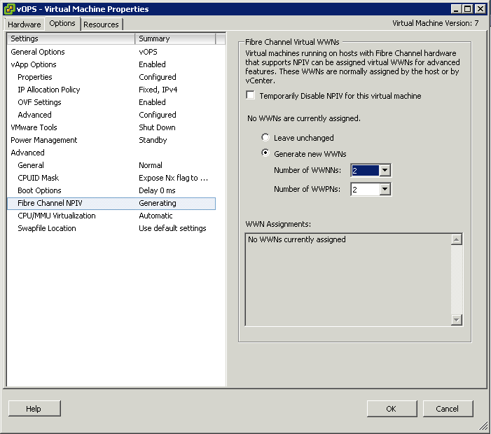
  • Click the Options tab, and select Fibre Channel NPIV
  • (Optional) Select the Temporarily Disable NPIV for this virtual machine check box
  • Select Generate new WWNs.
  • Specify the number of WWNNs and WWPNs.
  • A minimum of 2 WWPNs are needed to support failover with NPIV. Typically only 1 WWN is created for each virtual machine.
  • Click Finish.
  • The host creates WWN assignments for the virtual machine.

NPIV

What to do next

Register newly created WWN in the fabric so that the virtual machine is able to log in to the switch, and assign storage LUNs to the WWN

NPIV Advantages

  • Granular security: Access to specific storage LUNs can be restricted to specific VMs using the VM WWN for zoning, in the same way that they can be restricted to specific physical servers.
  • Easier monitoring and troubleshooting: The same monitoring and troubleshooting tools used with physical servers can now be used with VMs, since the WWN and the fabric address that these tools rely on to track frames are now uniquely associated to a VM.
  • Flexible provisioning and upgrade: Since zoning and other services are no longer tied to the physical WWN “hard-wired” to the HBA, it is easier to replace an HBA. You do not have to reconfigure the SAN storage, because the new server can be pre-provisioned independently of the physical HBA WWN.
  • Workload mobility: The virtual WWN associated with each VM follows the VM when it is migrated across physical servers. No SAN reconfiguration is necessary when the work load is relocated to a new server.
  • Applications identified in the SAN: Since virtualized applications tend to be run on a dedicated VM, the WWN of the VM now identifies the application to the SAN.
  • Quality of Service (QoS): Since each VM can be uniquely identified, QoS settings can be extended from the SAN to VMs

Identify Supported HBA types

ce-HBA-fig1a

HBA Adapters

The three types of Host Bus Adapters (HBA) that you can use on an ESXi host are

  • Ethernet (iSCSI)
  • Fibre Channel
  • Fibre Channel over Ethernet (FCoE).
  • In addition to the hardware adapters there is software versions of the iSCSI and FCoE adapters (software FCoE is new with version 5) are available.

Compatibility Guide

To see all the results search VMware’s compatibility guide

Determine use cases for and configure VMware DirectPath I/O

pci

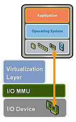
DirectPath I/O allows virtual machine access to physical PCI functions on platforms with an I/O Memory Management Unit.

The following features are unavailable for virtual machines configured with DirectPath

  • Hot adding and removing of virtual devices
  • Suspend and resume
  • Record and replay
  • Fault tolerance
  • High availability
  • DRS (limited availability. The virtual machine can be part of a cluster, but cannot migrate across hosts)
  •  Snapshots

Cisco Unified Computing Systems (UCS) through Cisco Virtual Machine Fabric Extender (VM-FEX) distributed switches support the following features for migration and resource management of virtual machines which use DirectPath I/O

  • Hot adding and removing of virtual devices
  • vMotion
  • Suspend and resume
  • High availability
  • DRS (limited availability
  •  Snapshots

Configure Passthrough Devices on a Host

  • Click on a Host
  • Select the Configuration Tab
  • Under Hardware, select Advanced Settings. You will see a warning message as per below

pass

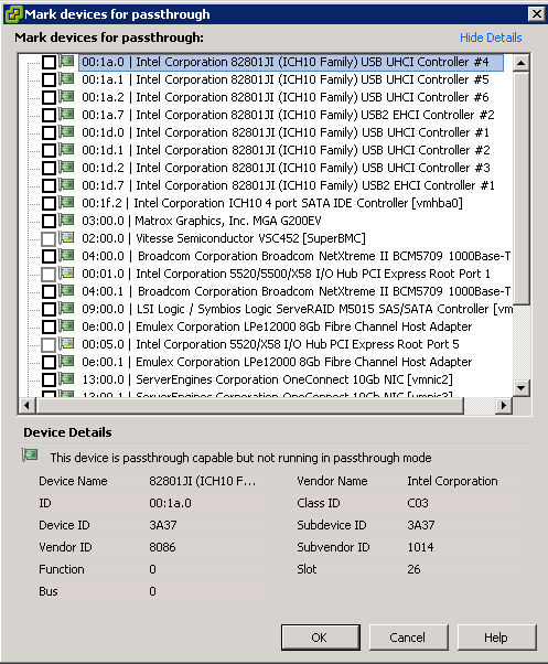
  • Click Configure Passthrough. The Passthrough Configuration page appears, listing all available passthrough devices.

passthrough

  • A green icon indicates that a device is enabled and active. An orange icon indicates that the state of the device has changed and the host must be rebooted before the device can be used

Capture

Configure a PCI Device on a VM

Prerequisites

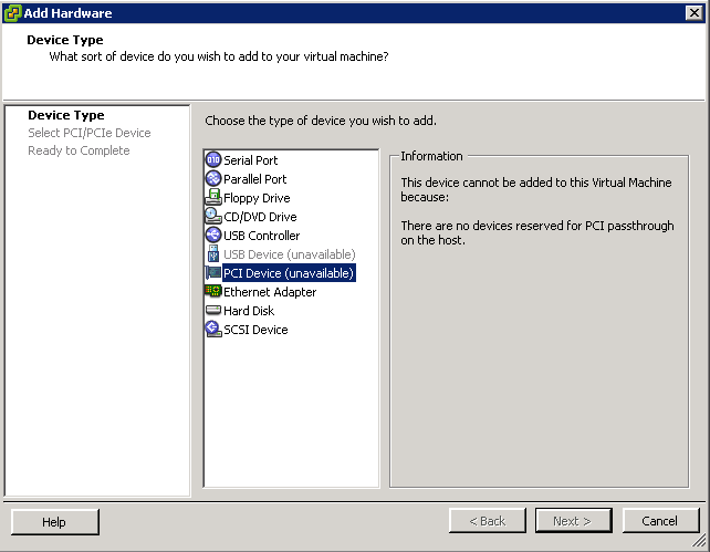
Verify that a Passthrough networking device is configured on the host of the virtual machine as per above instructions

Instructions

  • Select a VM
  • Power off the VM
  • From the Inventory menu, select Virtual Machine > Edit Settings
  • On the Hardware tab, click Add.
  • Select PCI Device and click Next
  • Select the Passthrough device to use
  • Click Finish
  • Power on VM

As per below I haven’t cofigured any pass thorugh devices but just to show you where the settings are

vmpci


RAID Levels

mirror-from-IKEA

What is RAID?

RAID stands for Redundant Array of Inexpensive (Independent) Disks. Data is distributed across the drives in one of several ways called “RAID levels”, depending on what level of redundancy and performance is required.

RAID Concepts

  • Striping
  • Mirroring
  • Parity or Error Correction
  • Hardware or Software RAID

RAID Levels

0,1,5 and 10 are the most commonly used RAID Levels
  • RAID 0

RAID_0.svg

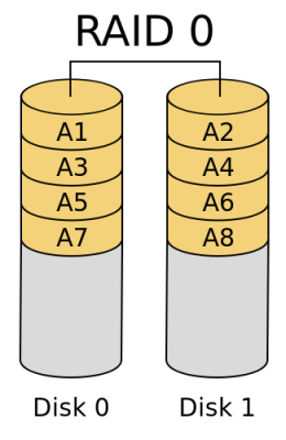
RAID 0 (block-level striping without parity or mirroring) has no (or zero) redundancy. It provides improved performance and additional storage but no fault tolerance. Hence simple stripe sets are normally referred to as RAID 0. Any drive failure destroys the array, and the likelihood of failure increases with more drives in the array. A single drive failure destroys the entire array because when data is written to a RAID 0 volume, the data is broken into fragments called blocks. The number of blocks is dictated by the stripe size, which is a configuration parameter of the array. The blocks are written to their respective drives simultaneously on the same sector. This allows smaller sections of the entire chunk of data to be read off each drive in parallel, increasing bandwidth. RAID 0 does not implement error checking, so any read error is uncorrectable. More drives in the array means higher bandwidth, but greater risk of data loss.
  • RAID 1

RAID_1.svg

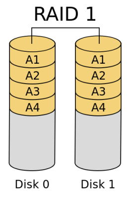
In RAID 1 (mirroring without parity or striping), data is written identically to two drives, thereby producing a “mirrored set”; the read request is serviced by either of the two drives containing the requested data, whichever one involves least seek time plus rotational latency. Similarly, a write request updates the stripes of both drives. The write performance depends on the slower of the two writes (i.e., the one that involves larger seek time and rotational latency); at least two drives are required to constitute such an array. While more constituent drives may be employed, many implementations deal with a maximum of only two. The array continues to operate as long as at least one drive is functioning. With appropriate operating system support, there can be increased read performance as data can be read off any of the drives in the array, and only a minimal write performance reduction; implementing RAID 1 with a separate controller for each drive in order to perform simultaneous reads (and writes) is sometimes called “multiplexing” (or “duplexing” when there are only two drives)

When the workload is write intensive you want to use RAID 1 or RAID 1+0
  • RAID 5

RAID_5.svg

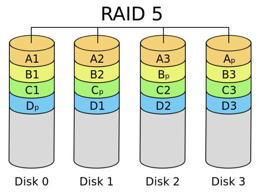
RAID 5 (block-level striping with distributed parity) distributes parity along with the data and requires all drives but one to be present to operate; the array is not destroyed by a single drive failure. Upon drive failure, any subsequent reads can be calculated from the distributed parity such that the drive failure is masked from the end user. However, a single drive failure results in reduced performance of the entire array until the failed drive has been replaced and the associated data rebuilt, because each block of the failed disk needs to be reconstructed by reading all other disks i.e. the parity and other data blocks of a RAID stripe. RAID 5 requires at least three disks. Best cost effective option providing both performance and redundancy. Use this for DB that is heavily read oriented. Write operations will be dependent on the RAID Controller used due to the need to calculate the parity data and write it across all the disks

When your workloads are read intensive it is best to use RAID 5 or RAID 6 and especially for web servers where most of the transactions are read

Don’t use RAID 5 for heavy write environments such as Database servers

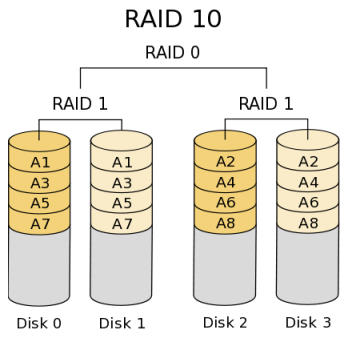
  • RAID 10 or 1+0 (Stripe of Mirrors)

RAID_10

In RAID 10 (mirroring and striping), data is written in stripes across primary disks that have been mirrored to the secondary disks. A typical RAID 10 configuration consists of four drives, two for striping and two for mirroring. A RAID 10 configuration takes the best concepts of RAID 0 and RAID 1, and combines them to provide better performance along with the reliability of parity without actually having parity as with RAID 5 and RAID 6. RAID 10 is often referred to as RAID 1+0 (mirrored+striped) This is the recommended option for any mission critical applications (especially databases) and requires a minimum of 4 disks. Performance on both RAID 10 and RAID 01 will be the same.

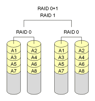
  • RAID 01 (Mirror of Stripes)

raid01

RAID 01 is also called as RAID 0+1. It requires a minimum of 3 disks. But in most cases this will be implemented as minimum of 4 disks. Imagine  two groups of 3 disks. For example, if you have total of 6 disks, create 2 groups. Group 1 has 3 disks and Group 2 has 3 disks.
Within the group, the data is striped. i.e In the Group 1 which contains three disks, the 1st block will be written to 1st disk, 2nd block to 2nd disk, and the 3rd block to 3rd disk. So, block A is written to Disk 1, block B to Disk 2, block C to Disk 3.
Across the group, the data is mirrored. i.e The Group 1 and Group 2 will look exactly the same. i.e Disk 1 is mirrored to Disk 4, Disk 2 to Disk 5, Disk 3 to Disk 6. This is why it is called “mirror of stripes”. i.e the disks within the groups are striped. But, the groups are mirrored. Performance on both RAID 10 and RAID 01 will be the same.
  • RAID 2

RAID2_arch.svg

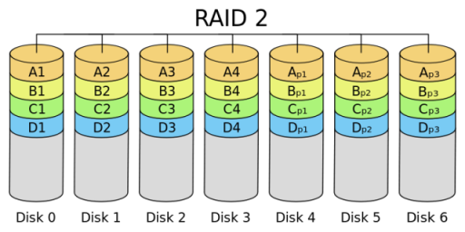
In RAID 2 (bit-level striping with dedicated Hamming-code parity), all disk spindle rotation is synchronized, and data is striped such that each sequential bit is on a different drive. Hamming-code parity is calculated across corresponding bits and stored on at least one parity drive. This theoretical RAID level is not used in practice. You need two groups of disks. One group of disks are used to write the data, another group is used to write the error correction codes. This is not used anymore. This is expensive and implementing it in a RAID controller is complex, and ECC is redundant now-a-days, as the hard disk themselves can do this themselves
  • RAID 3

RAID_3.svg

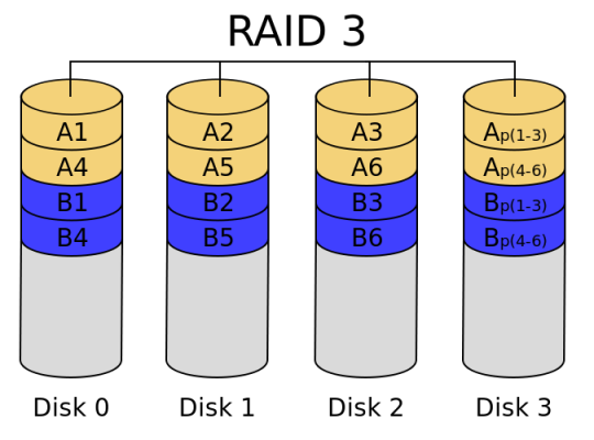
In RAID 3 (byte-level striping with dedicated parity), all disk spindle rotation is synchronized, and data is striped so each sequential byte is on a different drive. Parity is calculated across corresponding bytes and stored on a dedicated parity drive. Although implementations exist, RAID 3 is not commonly used in practice. Sequential read and write will have good performance. Random read and write will have worst performance.
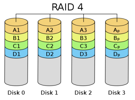
  • RAID 4

675px-RAID_4.svg

RAID 4 (block-level striping with dedicated parity) is identical to RAID 5 (see below), but confines all parity data to a single drive. In this setup, files may be distributed between multiple drives. Each drive operates independently, allowing I/O requests to be performed in parallel. However, the use of a dedicated parity drive could create a performance bottleneck; because the parity data must be written to a single, dedicated parity drive for each block of non-parity data, the overall write performance may depend a great deal on the performance of this parity drive.
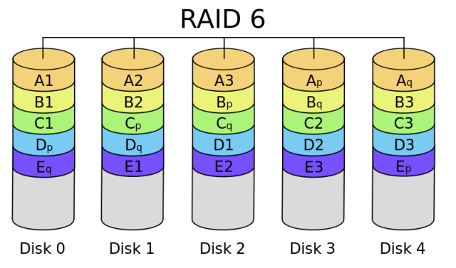
  • RAID 6

RAID_6.svg

RAID 6 (block-level striping with double distributed parity) provides fault tolerance of two drive failures; the array continues to operate with up to two failed drives. This makes larger RAID groups more practical, especially for high-availability systems. This becomes increasingly important as large-capacity drives lengthen the time needed to recover from the failure of a single drive. Single-parity RAID levels are as vulnerable to data loss as a RAID 0 array until the failed drive is replaced and its data rebuilt; the larger the drive, the longer the rebuild takes. Double parity gives additional time to rebuild the array without the data being at risk if a single additional drive fails before the rebuild is complete. Like RAID 5, a single drive failure results in reduced performance of the entire array until the failed drive has been replaced and the associated data rebuilt.

Don’t use for high random write workloads

What is Parity?

Parity data is used by some RAID levels to achieve redundancy. If a drive in the array fails, remaining data on the other drives can be combined with the parity data (using the Boolean XOR function) to reconstruct the missing data.

For example, suppose two drives in a three-drive RAID 5 array contained the following data:

Drive 1: 01101101
Drive 2: 11010100

To calculate parity data for the two drives, an XOR is performed on their data:

01101101
XOR  11010100
_____________
10111001

The resulting parity data, 10111001, is then stored on Drive 3.

Should any of the three drives fail, the contents of the failed drive can be reconstructed on a replacement drive by subjecting the data from the remaining drives to the same XOR operation. If Drive 2 were to fail, its data could be rebuilt using the XOR results of the contents of the two remaining drives, Drive 1 and Drive 3:

Drive 1: 01101101
Drive 3: 10111001

as follows:

10111001
XOR  01101101
_____________
11010100

The result of that XOR calculation yields Drive 2’s contents. 11010100 is then stored on Drive 2, fully repairing the array. This same XOR concept applies similarly to larger arrays, using any number of disks. In the case of a RAID 3 array of 12 drives, 11 drives participate in the XOR calculation shown above and yield a value that is then stored on the dedicated parity drive.

RAID Level Comparison
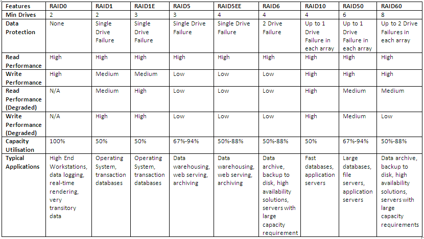
RAID

Interesting Link

http://www.miracleas.com/BAARF/RAID5_versus_RAID10.txt
 

What is Pluggable Storage Architecture (PSA) and Native Multipathing (NMP)?
Pluggable Storage Architecture

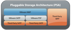
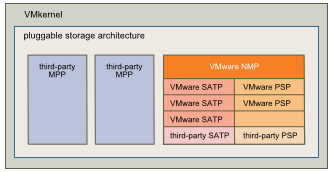
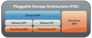
To manage storage multipathing, ESX/ESXi uses a special VMkernel layer which sits in the SCSI middle layer of the VMKernel I/O Stack, Pluggable Storage Architecture (PSA). The PSA is an open modular framework that coordinates the simultaneous operation of multiple multipathing plugins (MPPs). PSA is a collection of VMkernel APIs that allow third party hardware vendors to insert code directly into the ESX storage I/O path. This allows 3rd party software developers to design their own load balancing techniques and failover mechanisms for particular storage array. The PSA coordinates the operation of the NMP and any additional 3rd party MPP

What does PSA do?

  • Load and unload multipathing plug-ins
  • Uses predefined claim rules to assign each device to an MPP (One claim rule per device)
  • Handle physical path discovery and removal (through scanning)
  • Route I/O requests for a specific logical device to an appropriate multipathing plug-in
  • Handle I/O queuing to the physical storage HBAs and to the logical devices
  • Implement logical device bandwidth sharing between virtual machines
  • Provide logical device and physical path I/O statistics

Native Multipathing Plugin

The VMkernel multipathing plugin that ESX/ESXi provides, by default, is the VMware Native Multipathing Plugin (NMP). The NMP is an extensible module that manages subplugins. There are two types of NMP subplugins: Storage Array Type Plugins (SATPs), and Path Selection Plugins (PSPs). SATPs and PSPs can be built-in and provided by VMware, or can be provided by a third party.If more multipathing functionality is required, a third party can also provide an MPP to run in addition to, or as a replacement for, the default NMP.

VMware provides a generic Multipathing Plugin (MPP) called Native Multipathing Plugin (NMP) which supports all storage arrays on the Compatibility list

A single MPP can support multiple SATPs and PSPs. If a storage vendor has not supplied an MPP, SATP or PSP, VMware will use its own assigned by default

PSA

What does NMP do?

  1. Manages physical path claiming and unclaiming.
  2. Registers and de-registers logical devices
  3. Associates physical paths with logical devices.
  4. Processes I/O requests to logical devices
  5. Selects an optimal physical path for the request (load balance)
  6. Performs actions necessary to handle failures and request retries.
  7. Supports management tasks such as abort or reset of logical devices.

How it works

The ESX kernel (VMkernel) goes down through three layers when communicating with storage:

  1. In the top layer, VMware native NMP or third-party MPP software decides which SATP to use, or whether to use the native interface.
  2. The SATP layer includes native generic path selection (active/active, active/passive), standard ALUA, as well as allowing third-party plugins (SATP) to override its behavior. The SATP monitors these paths, reports changes, and initiates fail-over on the array as needed.
  3. At the PSP layer, software decides which physical channel to use for I/O requests.

In more detail

  • NMP assigns a SATP to every physical path to the logical device (datastore)
  • NMP associates paths to logical devices
  • NMP decides which PSP to use with the logical device.
  • The VM tells NMP an I/O is ready to send.
  • I/O is issued.
  • PSP is selected. Load-balances if applicable.
  • I/O is sent to  device.
  • Success:Device driver (Storage array) indicates I/O is complete. Failure: NMP calls appropriate SATP.
  • Success: NMP tells PSP I/O is complete. Failure: SATP interprets error codes and fails over to inactive paths.
  • Failure: PSP is called again to select which path to use for I/O excluding the failed path.
  • PSP checks every 300 seconds if the path is active again. SATP is responsible for doing the failover.

PSA Plugins

There are three types of PSA plugins for vSphere 4:

  1. Storage Array Type Plug-In (SATP)
  2. Path Selection Plug-in (PSP)
  3. A complete third-party multipathing software stack (MPP)

As is the case with VAAI, VMware includes a number of third-party plug-ins in the ESXi install. Users can simply activate many of these according to their needs, though some require additional fees and licensing.

SATP Plugins

SATPs allow load balancing across multiple paths, intelligent path selection, and over troubled conditions such as “chatter”, when passed rapidly fail back and forth between controllers.

The SATP has critical tasks to perform in the PSA stack:

  1. Decide which method of communication to use with the storage (PSA or native)
  2. Monitor the health of the physical I/O channels or paths
  3. Report any changes in the state of the paths up the stack
  4. Perform actions required to fail over storage between controllers on the array

VMware vSphere includes a variety of generic SATP plugins for storage arrays.

  • VMW_SATP_LOCAL – Local SATP for direct-attached devices
  • VMW_SATP_DEFAULT_AA – Generic for active/active arrays
  • VMW_SATP_DEFAULT_AP – Generic for active/passive arrays
  • VMW_SATP_ALUA – Asymmetric Logical Unit Access-compliant arrays
  • VMW_SATP_LSI – LSI/NetApp arrays from Dell, HDS, IBM, Oracle, SGI
  • VMW_SATP_SVC – IBM SVC-based systems (SVC, V7000, Actifio)
  • VVMW_SATP_SYMM – EMC Symmetrix DMX-3/DMX-4/VMAX, Invista
  • MW_SATP_CX – EMC/Dell CLARiiON  and Celerra (also VMW_SATP_ALUA_CX)
  • VMW_SATP_INV – EMC Invista and VPLEX
  • VMW_SATP_EQL – Dell EqualLogic systems

You can see which SATP plug-ins are available using the following esxcli command:

esxcli storage nmp satp list

PSP Plugins

In contrast to the diversity of VAAI and SATP plug-ins, the universe of path selection plug-ins is fairly small. Most storage arrays are supported with either Most Recently Used (MRU) or Fixed path selection approaches. Many also support Round Robin (RR) path selection. The only vendor with a specific PSP that is not also part of a full MPP (like EMC PowerPath or HDS HDLM) is Dell, which offers a special routed path selection plug-in for the EqualLogic iSCSI arrays.

  • VMW_PSP_MRU – Most-Recently Used (MRU) – Supports hundreds of storage arrays
  • VMW_PSP_FIXED – Fixed – Supports hundreds of storage arrays
  • VMW_PSP_RR – Round-Robin – Supports dozens of storage arrays
  • DELL_PSP_EQL_ROUTED – Dell EqualLogic iSCSI arrays

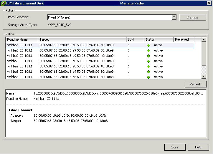
You can view the Path Polices in vCenter

  • Click on the Host
  • Click Configuration
  • Click Storage
  • Click on a Datastore and click Properties
  • Click Manage paths and you should see the below

paths

Array Types

  • Active /Active arrays use Fixed PSP Plugins
  • Active/Passive arrays use Most Recently Used PSP Plugins

ESXCLI Commands

  • esxcli storage nmp psp list

Capture1

  • esxcli nmp satp list

Capture2

  • esxcli storage core claimrule list

Capture3

  • esxcli storage nmp device list

Capture4

Virtual Disk Formats

The distinguishing factor among virtual disk formats is how data is zeroed out for the boundary of the virtual disk file. Zeroing out can be done either at run time (when the write happens to that area of the disk) or at the disk’s creation time.

There are three main virtual disk formats within VMware vSphere

  1. Zeroedthick (Lazy)
  2. Eagerzeroedthick.
  3. Thin

1. Zeroedthick – The “zeroedthick” format is the default and quickly creates a “flat” virtual disk file. The Zeroed Thick option is the pre-allocation of the entire boundary of the VMDK disk when it is created. This is the traditional fully provisioned disk format. In the vSphere Client, this is the default option. The virtual disk is allocated all of its provisioned space and immediately made accessible to the virtual machine.  A lazy zeroed disk is not zeroed up front which makes the provisioning very fast. However, because each block is zeroed out before it is written to for the first time there is added latency on first write.

2. Eagerzeroed  -This pre-allocates the disk space as well as each block of the file being pre-zeroed within the VMDK. Because of the increased I/O requirement, this requires additional time to write out the VMDK but eliminates the zeroing later on . Finally, the “eagerzeroedthick” format is used/required by VMware’s new Fault Tolerance (FT) feature

3. Thin – The thin virtual disk format is perhaps the easier option to understand. This is simply an as-used consumption model. This disk format is not pre-written to disk and is not zeroed out until run time

Performance Differences

So, why is this important? For one, there may be a perceived performance implication of having the disks thin provisioned. The thin provisioning white paper by VMware explains with more detail how each of these formats are used, as well as a quantification of the performance differences of eager zeroed thick and other formats. The white paper states that the performance impact is negligible for thin provisioning, and in all situations the results are nearly indistinguishable.

http://www.vmware.com/pdf/vsp_4_thinprov_perf.pdf