Archive for Objective 3 Tuning and Optimisation

Storing a Virtual Machine Swapfile in a different location

By default, swapfiles for a virtual machine are located on a VMFS3 datastore in the folder that contains the other virtual machine files. However, you can configure your host to place virtual machine swapfiles on an alternative datastore.

Why move the Swapfiles?

  • Place virtual machine swapfiles on lower-cost storage
  • Place virtual machine swapfiles on higher-performance storage.
  • Place virtual machine swapfiles on non replicated storage
  • Moving the swap file to an alternate datastore is a useful troubleshooting step if the virtual machine or guest operating system is experiencing failures, including STOP errors, read only filesystems, and severe performance degradation issues during periods of high I/O.

vMotion Considerations

Note: Setting an alternative swapfile location might cause migrations with vMotion to complete more slowly. For best vMotion performance, store virtual machine swapfiles in the same directory as the virtual machine. If the swapfile location specified on the destination host differs from the swapfile location specified on the source host, the swapfile is copied to the new location which causes the slower migration. Copying host-swap local pages between source- and destination host is a disk-to-disk copy process, this is one of the reasons why VMotion takes longer when host-local swap is used.

Swapfile Moving Caveats

  • If vCenter Server manages your host, you cannot change the swapfile location if you connect directly to the host by using the vSphere Client. You must connect to the vCenter Server system.
  • Migrations with vMotion are not allowed unless the destination swapfile location is the same as the source swapfile location. In practice, this means that virtual machine swapfiles must be located with the virtual machine configuration file.
  • Using host-local swap can affect DRS load balancing and HA failover in certain situations. So when designing an environment using host-local swap, some areas must be focused on to guarantee HA and DRS functionality.

DRS

If DRS decide to rebalance the cluster, it will migrate virtual machines to low utilized hosts. VMkernel tries to create a new swap file on the destination host during the VMotion process. In some scenarios, the host might not contain any free space in the VMFS datastore and DRS will not be able to vMotion any virtual machine to that host because the lack of free space. But the host CPU active and host memory active metrics were still monitored by DRS to calculate the load standard deviation used for its recommendations to balance the cluster. The lack of disk space on the local VMFS datastores influences the effectiveness of DRS and limits the options for DRS to balance the cluster.

High availability failover

The same applies when a HA isolation response occurs, when not enough space is available to create the virtual machine swap files, no virtual machines are started on the host. If a host fails, the virtual machines will only power-up on host containing enough free space on their local VMFS datastores. It might be possible that virtual machines will not power-up at-all if not enough free disk space is available

Procedure (Cluster Modification)

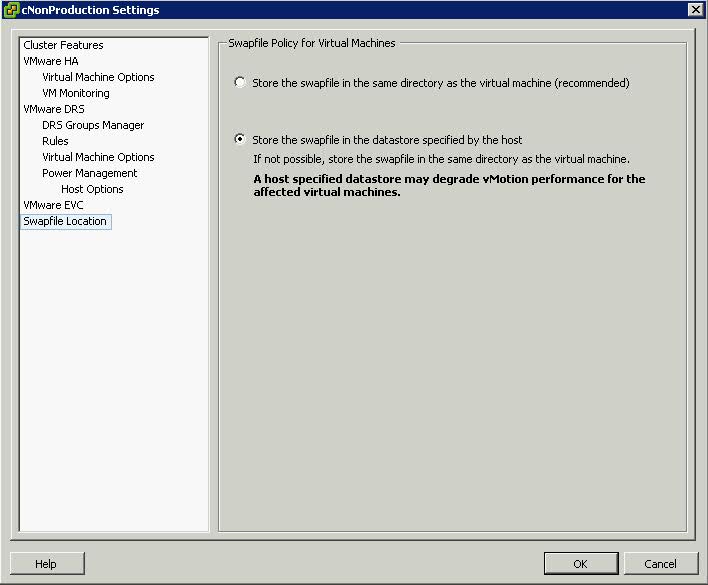
  • Right click the cluster
  • Edit Settings
  • Click Swap File Location
  • Select Store the Swapfile in the Datastore specified by the Host

Procedure (Host Modification)

If the host is part of a cluster, and the cluster settings specify that swapfiles are to be stored in the same directory as the virtual machine, you cannot edit the swapfile location from the host configuration tab. To change the swapfile location for such a host, use the Cluster Settings dialog box.

swapfile2

  • Click the Inventory button in the navigation bar, expand the inventory as needed, and click the appropriate managed host.
  • Click the Configuration tab to display configuration information for the host.
  • Click the Virtual Machine Swapfile Location link.
  • The Configuration tab displays the selected swapfile location. If configuration of the swapfile location is not supported on the selected host, the tab indicates that the feature is not supported.
  • Click Edit.
  • Select either Store the swapfile in the same directory as the virtual machine or Store the swapfile in a swapfile datastore selected below.
  • If you select Store the swapfile in a swapfile datastore selected below, select a datastore from the list.
  • Click OK.
  • The virtual machine swapfile is stored in the location you selected.

VMware Resource Management (Memory)

VMware® ESX(i)™ is a hypervisor designed to efficiently manage hardware resources including CPU, memory, storage, and network among multiple, concurrent virtual machines.

Memory Overcommittment

The concept of memory overcommitment is fairly simple: host memory is overcommitted when the total amount of guest physical memory of the running virtual machines is larger than the amount of actual host memory. ESX supports memory overcommitment from the very first version, due to two important benefits it provides:

  • Higher memory utilization: With memory overcommitment, ESX ensures that host memory is consumed by active guest memory as much as possible. Typically, some virtual machines may be lightly loaded compared to others. Their memory may be used infrequently, so for much of the time their memory will sit idle. Memory overcommitment allows the hypervisor to use memory reclamation techniques to take the inactive or unused host physical memory away from the idle virtual machines and give it to other virtual machines that will actively use it.
  • Higher consolidation ratio: With memory overcommitment, each virtual machine has a smaller footprint in host memory usage, making it possible to fit more virtual machines on the host while still achieving good performance for all virtual machines. For example, as shown in Figure 3, you can enable a host with 4G host physical memory to run three virtual machines with 2G guest physical memory each. Without memory overcommitment, only one virtual machine can be run because the hypervisor cannot reserve host memory for more than one virtual machine, considering that each virtual machine has overhead memory.

ESX uses several innovative techniques to reclaim virtual machine memory, which are:

  • Transparent page sharing (TPS)
  • Reclaims memory by removing redundant pages with identical content
  • Ballooning
  • Reclaims memory by artificially increasing the memory pressure inside the guest
  • Hypervisor/Host swapping
  • Reclaims memory by having ESX directly swap out the virtual machine’s memory
  • Memory compression
  • Reclaims memory by compressing the pages that need to be swapped out

Transparent Page Sharing

When multiple virtual machines are running, some of them may have identical sets of memory content. This presents opportunities for sharing memory across virtual machines (as well as sharing within a single virtual machine). For example, several virtual machines may be running the same guest operating system, have the same applications, or contain the same user data. With page sharing, the hypervisor can reclaim the redundant copies and keep only one copy, which is shared by multiple virtual machines in the host physical memory. As a result, the total virtual machine host memory consumption is reduced and a higher level of memory overcommitment is possible.
In ESX, the redundant page copies are identified by their contents. This means that pages with identical content can be shared regardless of when, where, and how those contents are generated. ESX scans the content of guest physical memory for sharing opportunities. Instead of comparing each byte of a candidate guest physical page to other pages, an action that is prohibitively expensive, ESX uses hashing to identify potentially identical pages.
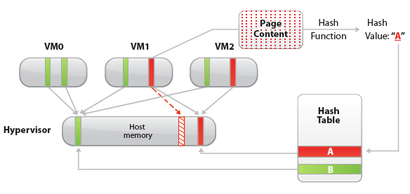
A hash value is generated based on the candidate guest physical page’s content. The hash value is then used as a key to look up a global hash table, in which each entry records a hash value and the physical page number of a shared page. If the hash value of the candidate guest physical page matches an existing entry, a full comparison of the page contents is performed to exclude a false match. Once the candidate guest physical page’s content is confirmed to match the content of an existing shared host physical page, the guest physical to host physical mapping of the candidate guest physical page is changed to the shared host physical page, and the redundant host memory copy (the page pointed to by the dashed arrow in the Figure above) is reclaimed. This remapping is invisible to the virtual machine and inaccessible to the guest operating system. Because of this invisibility, sensitive information cannot be leaked from one virtual machine to another.

A standard copy-on-write (CoW) technique is used to handle writes to the shared host physical pages. Any attempt to write to the shared pages will generate a minor page fault. In the page fault handler, the hypervisor will transparently create a private copy of the page for the virtual machine and remap the affected guest physical page to this private copy. In this way, virtual machines can safely modify the shared pages without disrupting other virtual machines sharing that memory. Note that writing to a shared page does incur overhead compared to writing to non-shared pages due to the extra work performed in the page fault handler.
In VMware ESX, the hypervisor scans the guest physical pages randomly with a base scan rate specified by Mem.ShareScanTime, which specifies the desired time to scan the virtual machine’s entire guest memory. The maximum number of scanned pages per second in the host and the maximum number of per-virtual machine scanned pages, (that is, Mem.ShareScanGHz and Mem.ShareRateMax respectively) can also be specified in ESX advanced settings. An example is shown in the Figure below

The default values of these three parameters are carefully chosen to provide sufficient sharing opportunities while keeping the CPU overhead negligible. In fact, ESX intelligently adjusts the page scan rate based on the amount of current shared pages. If the virtual machine’s page sharing opportunity seems to be low, the page scan rate will be reduced accordingly and vice versa. This optimization further mitigates the overhead of page sharing.
In hardware-assisted memory virtualization (for example, Intel EPT Hardware Assist and AMD RVI Hardware Assist systems, ESX will automatically back guest physical pages with large host physical pages (2MB contiguous memory region instead of 4KB for regular pages) for better performance due to less TLB misses. In such systems, ESX will not share those large pages because: 1) the probability of finding two large pages having identical contents is low, and 2) the overhead of doing a bit-by-bit comparison for a 2MB page is much larger than for a 4KB page. However, ESX still generates hashes for the 4KB pages within each large page. Since ESX will not swap out large pages, during host swapping, the large page will be broken into small pages so that these pre-generated hashes can be used to share the small pages before they are swapped out. In short, we may not observe any page sharing for hardware-assisted memory virtualization systems until host memory is overcommitted.

Ballooning

Ballooning is a completely different memory reclamation technique compared to transparent page sharing. Before describing the technique, it is helpful to review why the hypervisor needs to reclaim memory from virtual machines. Due to the virtual machine’s isolation, the guest operating system is not aware that it is running inside a virtual machine and is not aware of the states of other virtual machines on the same host. When the hypervisor runs multiple virtual machines and the total amount of the free host memory becomes low, none of the virtual machines will free guest physical memory because the guest operating system cannot detect the host’s memory shortage. Ballooning makes the guest operating system aware of the low memory status of the host.

In ESX, a balloon driver is loaded into the guest operating system as a pseudo-device driver.
VMware Tools must be installed in order to enable ballooning. This is recommended for all workloads. It has no external interfaces to the guest operating system and communicates with the hypervisor through a private channel. The balloon driver polls the hypervisor to obtain a target balloon size. If the hypervisor needs to reclaim virtual machine memory, it sets a proper target balloon size for the balloon driver, making it “inflate” by allocating guest physical pages within the virtual machine. The figure below illustrates the process of the balloon inflating

In the figure below, four guest physical pages are mapped in the host physical memory. Two of the pages are used by the guest application and the other two pages (marked by stars) are in the guest operating system free list. Note that since the hypervisor cannot identify the two pages in the guest free list, it cannot reclaim the host physical pages that are backing them. Assuming the hypervisor needs to reclaim two pages from the virtual machine, it will set the target balloon size to two pages. After obtaining the target balloon size, the balloon driver allocates two guest physical pages inside the virtual machine and pins them, as shown in Figure b. Here, “pinning” is achieved through the guest operating system interface, which ensures that the pinned pages cannot be paged out to disk under any circumstances. Once the memory is allocated, the balloon driver notifies the hypervisor about the page numbers of the pinned guest physical memory so that the hypervisor can reclaim the host physical pages that are backing them. In Figure b, dashed arrows point at these pages. The hypervisor can safely reclaim this host physical memory because neither the balloon driver nor the guest operating system relies on the contents of these pages. This means that no processes in the virtual machine will intentionally access those pages to read/write any values. Thus, the hypervisor does not need to allocate host physical memory to store the page contents. If any of these pages are re-accessed by the virtual machine for some reason, the hypervisor will treat it as a normal virtual machine memory allocation and allocate a new host physical page for the virtual machine. When the hypervisor decides to deflate the balloon—by setting a smaller target balloon size—the balloon driver deallocates the pinned guest physical memory, which releases it for the guest’s applications.
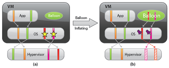

Typically, the hypervisor inflates the virtual machine balloon when it is under memory pressure. By inflating the balloon, a virtual machine consumes less physical memory on the host, but more physical memory inside the guest. As a result, the hypervisor offloads some of its memory overload to the guest operating system while slightly loading the virtual machine. That is, the hypervisor transfers the memory pressure from the host to the virtual machine. Ballooning induces guest memory pressure. In response, the balloon driver allocates and pins guest physical memory. The guest operating system determines if it needs to page out guest physical memory to satisfy the balloon driver’s allocation requests. If the virtual machine has plenty of free guest physical memory, inflating the balloon will induce no paging and will not impact guest performance. In this case, as illustrated in the figure, the balloon driver allocates the free guest physical memory from the guest free list. Hence, guest-level paging is not necessary. However, if the guest is already under memory pressure, the guest operating system decides which guest physical pages to be paged out to the virtual swap device in order to satisfy the balloon driver’s allocation requests. The genius of ballooning is that it allows the guest operating system to intelligently make the hard decision about which pages to be paged out without the hypervisor’s involvement.

Hypervisor/Host Swapping

In the cases where ballooning and transparent page sharing are not sufficient to reclaim memory, ESX employs hypervisor swapping to reclaim memory. At virtual machine startup, the hypervisor creates a separate swap file for the virtual machine. Then, if necessary, the hypervisor can directly swap out guest physical memory to the swap file, which frees host physical memory for other virtual machines.
Besides the limitation on the reclaimed memory size, both page sharing and ballooning take time to reclaim memory. The page-sharing speed depends on the page scan rate and the sharing opportunity. Ballooning speed relies on the guest operating system’s response time for memory allocation.
In contrast, hypervisor swapping is a guaranteed technique to reclaim a specific amount of memory within a specific amount of time. However, hypervisor swapping is used as a last resort to reclaim memory from the virtual machine due to the following limitations on performance:

  • Page selection problems: Under certain circumstances, hypervisor swapping may severely penalize guest performance. This occurs when the hypervisor has no knowledge about which guest physical pages should be swapped out, and the swapping may cause unintended interactions with the native memory management policies in the guest operating system.
  • Double paging problems: Another known issue is the double paging problem. Assuming the hypervisor swaps out a guest physical page, it is possible that the guest operating system pages out the same physical page, if the guest is also under memory pressure. This causes the page to be swapped in from the hypervisor swap device and immediately to be paged out to the virtual machine’s virtual swap device.

Page selection and double-paging problems exist because the information needed to avoid them is not available to the hypervisor.

  • High swap-in latency: Swapping in pages is expensive for a VM. If the hypervisor swaps out a guest page and the guest subsequently accesses that page, the VM will get blocked until the page is swapped in from disk. High swap-in latency, which can be tens of milliseconds, can severely degrade guest performance.

ESX mitigates the impact of interacting with guest operating system memory management by randomly selecting the swapped guest physical pages.

Memory Compression

The idea of memory compression is very straightforward: if the swapped out pages can be compressed and stored in a compression cache located in the main memory, the next access to the page only causes a page decompression which can be an order of magnitude faster than the disk access. With memory compression, only a few uncompressible pages need to be swapped out if the compression cache is not full. This means the number of future synchronous swap-in operations will be reduced. Hence, it may improve application performance significantly when the host is in heavy memory pressure. In ESX 4.1, only the swap candidate pages will be compressed. This means ESX will not proactively compress guest pages when host swapping is not necessary. In other words, memory compression does not affect workload performance when host memory is undercommitted.

Reclaiming Memory through Compression

Figure a,b and c illustrates how memory compression reclaims host memory compared to host swapping. Assuming ESX needs to reclaim two 4KB physical pages from a VM through host swapping, page A and B are the selected pages (Figure a,b,c). With host swapping only, these two pages will be directly swapped to disk and two physical pages are reclaimed (Figure b). However, with memory compression, each swap candidate page will be compressed and stored using 2KB of space in a per-VM compression cache. Note that page compression would be much faster than the normal page swap out operation which involves a disk I/O. Page compression will fail if the compression ratio is less than 50% and the uncompressible pages will be swapped out. As a result, every successful page compression is accounted for reclaiming 2KB of physical memory. As illustrated in Figure c, pages A and B are compressed and stored as half-pages in the compression cache. Although both pages are removed from VM guest memory, the actual reclaimed memory size is one page.

If any of the subsequent memory access misses in the VM guest memory, the compression cache will be checked first using the host physical page number. If the page is found in the compression cache, it will be decompressed and push back to the guest memory. This page is then removed from the compression cache. Otherwise, the memory request is sent to the host swap device and the VM is blocked.

Managing Per-VM Compression Cache

The per-VM compression cache is accounted for by the VM’s guest memory usage, which means ESX will not allocate additional host physical memory to store the compressed pages. The compression cache is transparent to the guest OS. Its size starts with zero when host memory is undercommitted and grows when virtual machine memory starts to be swapped out.
If the compression cache is full, one compressed page must be replaced in order to make room for a new compressed page. An age-based replacement policy is used to choose the target page. The target page will be decompressed and swapped out. ESX will not swap out compressed pages.
If the pages belonging to compression cache need to be swapped out under severe memory pressure, the compression cache size is reduced and the affected compressed pages are decompressed and swapped out.
The maximum compression cache size is important for maintaining good VM performance. If the upper bound is too small, a lot of replaced compressed pages must be decompressed and swapped out. Any following swap-ins of those pages will hurt VM performance. However, since compression cache is accounted for by the VM’s guest memory usage, a very large compression cache may waste VM memory and unnecessarily create VM memory pressure especially when most compressed pages would not be touched in the future. In ESX 4.1, the default maximum compression cache size is conservatively set to 10% of configured VM memory size. This value can be changed through the vSphere Client in Advanced Settings by changing the value for Mem.MemZipMaxPct.

When to reclaim Memory

ESX maintains four host free memory states: high, soft, hard, and low, which are reflected by four thresholds: 6%, 4%, 2%, and 1% of host memory respectively. Figure 8 shows how the host free memory state is reported in esxtop.
By default, ESX enables page sharing since it opportunistically “frees” host memory with little overhead. When to use ballooning or swapping (which activates memory compression) to reclaim host memory is largely determined by the current host free memory state.

In the high state, the aggregate virtual machine guest memory usage is smaller than the host memory size. Whether or not host memory is overcommitted, the hypervisor will not reclaim memory through ballooning or swapping. (This is true only when the virtual machine memory limit is not set.)
If host free memory drops towards the soft threshold, the hypervisor starts to reclaim memory using ballooning. Ballooning happens before free memory actually reaches the soft threshold because it takes time for the balloon driver to allocate and pin guest physical memory. Usually, the balloon driver is able to reclaim memory in a timely fashion so that the host free memory stays above the soft threshold.
If ballooning is not sufficient to reclaim memory or the host free memory drops towards the hard threshold, the hypervisor starts to use swapping in addition to using ballooning. During swapping, memory compression is activated as well. With host swapping and memory compression, the hypervisor should be able to quickly reclaim memory and bring the host memory state back to the soft state.
In a rare case where host free memory drops below the low threshold, the hypervisor continues to reclaim memory through swapping and memory compression, and additionally blocks the execution of all virtual machines that consume more memory than their target memory allocations.
In certain scenarios, host memory reclamation happens regardless of the current host free memory state. For example, even if host free memory is in the high state, memory reclamation is still mandatory when a virtual machine’s memory usage exceeds its specified memory limit. If this happens, the hypervisor will employ ballooning and, if necessary, swapping and memory compression to reclaim memory from the virtual machine until the virtual machine’s host memory usage falls back to its specified limit

VMware vSphere 5 Memory Management and Monitoring diagram

The diagram from this KB is fantastic for showing the interoperability between Memory Management Techniques

KB2017642
DRS

What is DRS?

A DRS cluster is a collection of ESXi hosts and associated virtual machines with shared resources and a shared interface. Before you can obtain the benefits of cluster-level resource management you must create a DRS cluster.
When you add a host to a DRS cluster, the host’s resources become part of the cluster’s resources. In addition to this aggregation of resources, with a DRS cluster you can support cluster-wide resource pools and enforce cluster-level resource allocation policies. The following cluster-level resource management capabilities are also available.

DRS must use Shared Storage and a vMotion network

  • Load Balancing

The distribution and usage of CPU and memory resources for all hosts and virtual machines in the cluster are continuously monitored. DRS compares these metrics to an ideal resource utilization given the attributes of the cluster’s resource pools and virtual machines, the current demand, and the imbalance target. It then performs (or recommends) virtual machine migrations accordingly. When you first power on a virtual machine in the cluster, DRS attempts to maintain proper load balancing by either placing the virtual machine on an appropriate host or making a recommendation.

  • Power management

When the vSphere Distributed Power Management (DPM) feature is enabled, DRS compares cluster- and host-level capacity to the demands of the cluster’s virtual machines, including recent historical demand. It places (or recommends placing) hosts in standby power mode if sufficient excess capacity is found or powering on hosts if capacity is needed. Depending on the resulting host power state recommendations, virtual machines might need to be migrated to and from the hosts as well.

  • Affinity Rules

You can control the placement of virtual machines on hosts within a cluster, by
assigning affinity rules.

DRS, EVC and FT

Depending on whether or not Enhanced vMotion Compatibility (EVC) is enabled, DRS behaves differently when you use vSphere Fault Tolerance (vSphere FT) virtual machines in your cluster.

DRS

Migration Recommendations

The system supplies as many recommendations as necessary to enforce rules and balance the resources of the cluster. Each recommendation includes the virtual machine to be moved, current (source) host and destination host, and a reason for the recommendation. The reason can be one of the following:

  • Balance average CPU loads or reservations
  • Balance average memory loads or reservations
  • Satisfy resource pool reservations
  • Satisfy an affinity rule.
  • Host is entering maintenance mode or standby mode.

Note: If you are using the vSphere Distributed Power Management (DPM) feature, in addition to migration recommendations, DRS provides host power state recommendations

Using DRS Affinity Rules

You can control the placement of virtual machines on hosts within a cluster by using affinity rules. You can create two types of rules.

  • VM-Host

Used to specify affinity or anti-affinity between a group of virtual machines and a group of hosts. An affinity rule specifies that the members of a selected virtual machine DRS group can or must run on the members of a specific host DRS group. An anti-affinity rule specifies that the members of a selected virtual machine DRS group cannot run on the members of a specific host DRS group.

  • VM-VM

Used to specify affinity or anti-affinity between individual virtual machines. A rule specifying affinity causes DRS to try to keep the specified virtual machines together on the same host, for example, for performance reasons. With an anti-affinity rule, DRS tries to keep the specified virtual machines apart, for example, so that when a problem occurs with one host, you do not lose both virtual machines. When you add or edit an affinity rule, and the cluster’s current state is in violation of the rule, the system continues to operate and tries to correct the violation. For manual and partially automated DRS clusters, migration recommendations based on rule fulfillment and load balancing are presented for approval. You are not required to fulfill the rules, but the corresponding recommendations remain until the rules are fulfilled.

To check whether any enabled affinity rules are being violated and cannot be corrected by DRS, select the cluster’s DRS tab and click Faults. Any rule currently being violated has a corresponding fault on this page.
Read the fault to determine why DRS is not able to satisfy the particular rule. Rules violations also produce a log event.

DRS Automation Levels

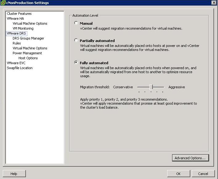
Someone at my work asked me about these levels and wanted an explanation for the Aggressive Level. He said he envisaged machines continually moving around in a state of perpetual motion. Lets find out!

Just as a note, you access DRS Automation Level Settings by right clicking on the cluster and selecting Edit Settings, then selecting VMware DRS

There are 3 settings

  1. Manual – vCenter will suggest migration recommendations for virtual machines
  2. Partially Automated – Virtual machines will be placed onto hosts at power on and vCenter will suggest migration recommendations for virtual machines
  3. Fully Automated – Virtual machines will be automatically places on to hosts when powered on and will be automatically migrated from one host to another to optimize resource usage

For Fully Automated there is a slider called Migration threshold

You can move the slider to use one of the five levels

  • Level 1 – Apply only five-star recommendations. Includes recommendations that must be followed to satisfy cluster constraints, such as affinity rules and host maintenance. This level indicates a mandatory move, required to satisfy an affinity rule or evacuate a host that is entering maintenance mode.
  • Level 2 – Apply recommendations with four or more stars. Includes Level 1 plus recommendations that promise a significant improvement in the cluster’s load balance.
  • Level 3 – Apply recommendations with three or more stars. Includes Level 1 and 2 plus recommendations that promise a good improvement in the cluster’s load balance.
  • Level 4 – Apply recommendations with two or more stars. Includes Level 1-3 plus recommendations that promise a moderate improvement in the cluster’s load balance.
  • Level 5 – Apply all recommendations. Includes Level 1-4 plus recommendations that promise a slight improvement in the cluster’s load balance.

Some interesting facts

  • DRS has a threshold of up to 60 vMotion events per hour
  • It will check for imbalances in the cluster once every five minutes

vCenter Console

DRS

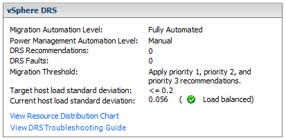
When the Current host load standard deviation exceeds the target host load standard deviation, DRS will make recommendations and take action based on the automation level and migration threshold

The target host load standard deviation is derived from the migration threshold setting. A load is considered imbalanced as long as the current value exceeds the migration threshold.

Each host has a host load metric based upon the CPU and memory resources in use. It is described as the sum of expected virtual machine loads divided by the capacity of the host. The LoadImbalanceMetric also known as the current host load standard deviation is the standard deviation (average of averages) of all host load metrics in a cluster.

DRS decides what virtual machines are migrated based on simulating a move and recalculating the current host load standard deviation and making a recommendation. As part of this simulation, a cost benefit and risk analysis is performed to determine best placement. DRS will continue to perform simulations and will make recommendations as long as the current host load exceeds the target host load.

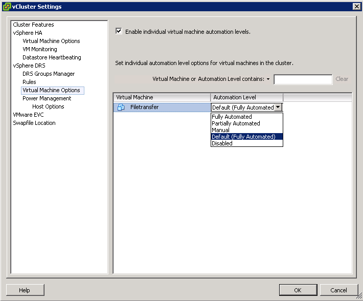
Properly size virtual machine automation levels based on Application Requirements

  • When a virtual machine is powered on, DRS is responsible for performing initial placement. During initial placement, DRS considers the “worst case scenario” for a VM. For example, when a new server that has been overspec’d gets powered on, DRS will actively attempt to identify a host that can guarantee that CPU and RAM to the VM. This is due to the fact that historical resource utilization statistics for the VM are unavailable. If DRS cannot find a cluster host able to accommodate the VM, it will be forced to “defragment” the cluster by moving other VMs around to account for the one being powered on. As such, VMs should be be sized based on their current workload.
  • When performing an assessment of a physical environment as part of a vSphere migration, an administrator should leverage the resource utilization data from VMware Capacity Planner in allocating resources to VMs.
  • Do not set VM reservations too high as this can affect DRS Balancing DRS might not have excess resources to move VMs around
  • Group Virtual Machines for a multi-tier service into a Resource Pool
  • Don’t forget to calculate memory overhead when sizing VMs into clusters
  • Use Resource Settings such as Shares, Limits and Reservations only when necessary

Automation

  • You might want to keep VMs on the same host if they are part of a tiered application that runs on multiple VMs, such as a web, application, or database server.
  • You might want to keep VMs on different hosts for servers that are clustered or redundant, such as Active Directory (AD), DNS, or web servers, so that a single ESX failure does not affect both servers at the same time. Doing this ensures that at least one will stay up and remain available while the other recovers from a host failure.
  • You might want to separate servers that have high I/O workloads so that you do not overburden a specific host with too many high-workload servers.
  • Keep servers like vCenter, the vCenter DB and Domain Controllers as a high priority

RESXTOP and ESXTOP

ESXTOP and RESXTOP

Are used to analyze real-time performance data from an individual ESX or ESXi server.

The fundamental difference between resxtop and esxtop is that you can use resxtop remotely, whereas you can start extop only through the ESXi Shell of a local ESXi host.

You can start either utility in one of three modes:

  • Interactive (default)
  • Batch
  • Replay

Running ESXTOP/RESXTOP

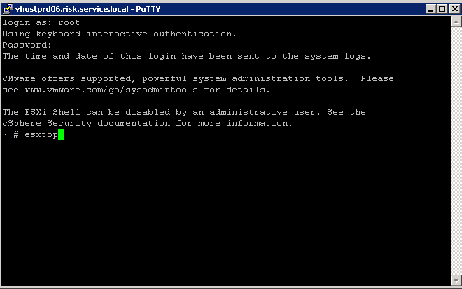
Type esxtop/resxtop into one of the following consoles

  • Putty
  • vMA (vSphere Management Assistant) virtual appliance.
  • vCLI
  • Power CLI

esxtop59

When running RESXTOP you will have to specify the ESX or ESXi server hostname, username, and password, as you see below

What you will see first

  • Global Statistics

  • Up time

The elapsed time since the server has been powered on.

  • Number of worlds

The total number of worlds on ESX(i) Server (Like Processes)

  • CPU load average

The arithmetic mean of CPU loads in 1 minute, 5 minutes, and 15 minutes, based on 6-second samples. CPU load accounts the run time and ready time for all the groups on the host.

A load average of 0.50 means that the physical CPUs on the ESXi system
are half utilized.

A load average of 1.00 means that the physical CPUs on the ESXi system
are fully utilized.

A load average of 2.00 means that means that the physical CPUs on the ESXi system
are doubly utilized and the ESXi system might need twice as many physical CPUs as are currently available.

Accessing the 8 different displays

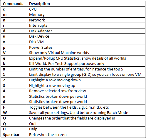
You’ll find that ESXTOP/RESXTOP has 8 different “displays” that show CPU, interrupt, memory, network, disk adapter, disk interface, disk VM, and power management. These are accessed by typing the letters below

Commands by letter

esxtop

Running esxtop in Batch Mode

  • Log into the host using whichever console you feel comfortable with. E.g. Putty
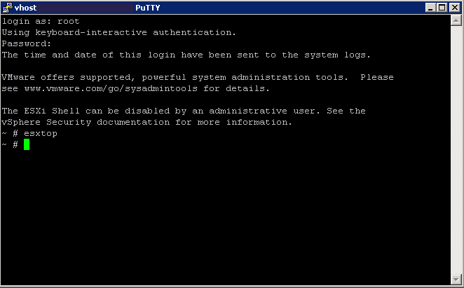
  • Type esxtop
  • Type V (Capital V) to just show the VMs

esxtop1

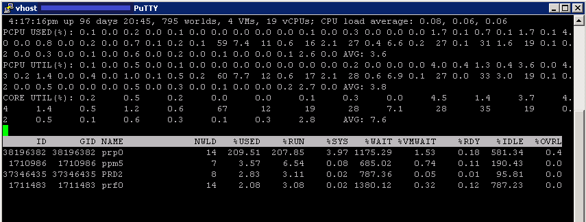
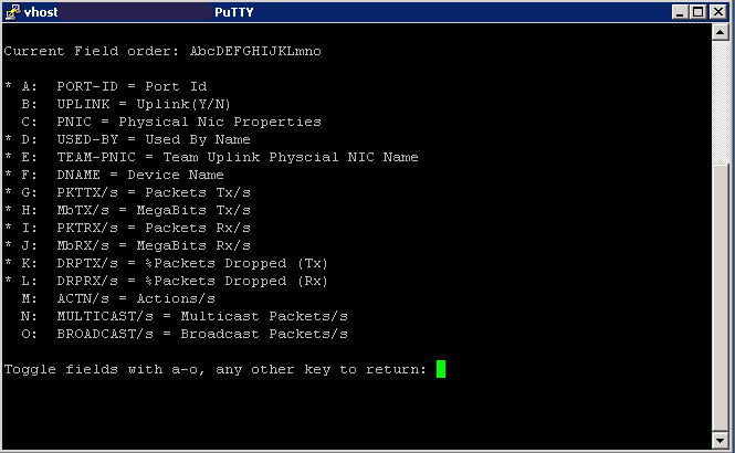
  • By default you are on the CPU Screen. If you then type f (lower case) you can toggle between what CPU fields to view. Type the letter to activate the relevant field

esxtop2

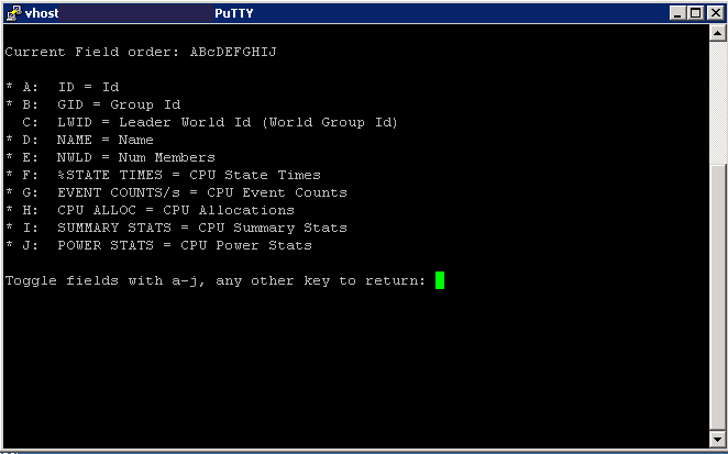
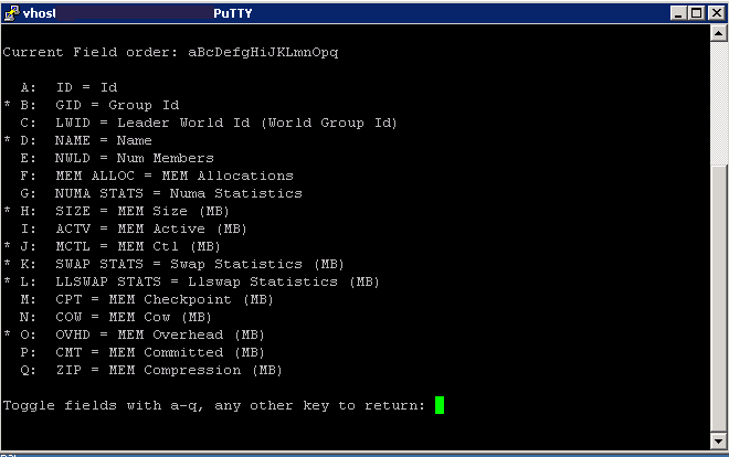
  • Press any key to return to the main screen and now press m (lower case) for Memory and then press f to see the fields. Type the letter to activate the relevant field

esxtop3

  • Press any key to return to the main screen then type n (lower case) for Network and type f to see the fields. Type the letter to activate the relevant field

esxtop4

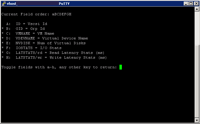
  • Press any key to return to the main screen and now press v (lower case) for VM Disk and then press f to see the fields. Type the letter to activate the relevant field.

esxtop5

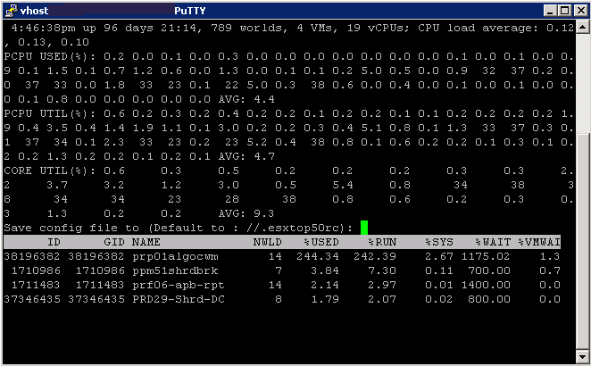
  • Now you have selected all your fields, you need to press W (Capital W) to save your settings then press Enter

esxtop6

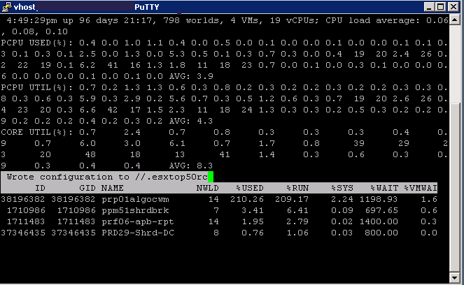
  • You should see the following screen flash up quickly

esxtop7

  • Type q to quit and go back to your normal command line

esxtop8

  • You now need to run it in batch mode and save the results to a .csv file:
  • Type esxtop -b -a -d 2 -n 1800 > /tmp/esxtopcapture.csv

Where “-b” stands for batch mode, “-d 2″ is a delay of 2 seconds and “-n 1800″ are 3600 iterations. In this specific case esxtop will log all metrics for 1 Hour. If you want to record all metrics make sure to add “-a” to your string.

esxtopbatch

Analysing Data

You can use multiple tools to analyze the captured data. Underlined are links to the software

  1. VisualEsxtop
  2. perfmon
  3. excel
  4. esxplot

VisualEsxtop

VisualEsxtop is an enhanced version of resxtop and esxtop. VisualEsxtop can connect to VMware vCenter Server or ESX hosts, and display ESX server stats with a better user interface and more advanced features.

Features

  1. Live connection to ESX host or vCenter Server
  2. Flexible way of batch output
  3. Load batch output and replay them
  4. Multiple windows to display different data at the same time
  5. Line chart for selected performance counters
  6. Flexible counter selection and filtering
  7. Embedded tooltip for counter description
  8. Color coding for important counters

Instructions

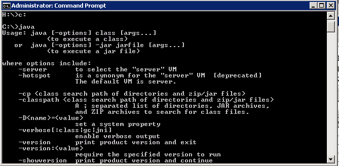
  • Once it is download you must make sure that Java is installed or VisualEsxtop will not run. We have JRE 6 Update 29 installed. You can check this by running cmd.exe and typing java

java

  • If you don’t have Java installed correctly then you will get the following message

esxtop60

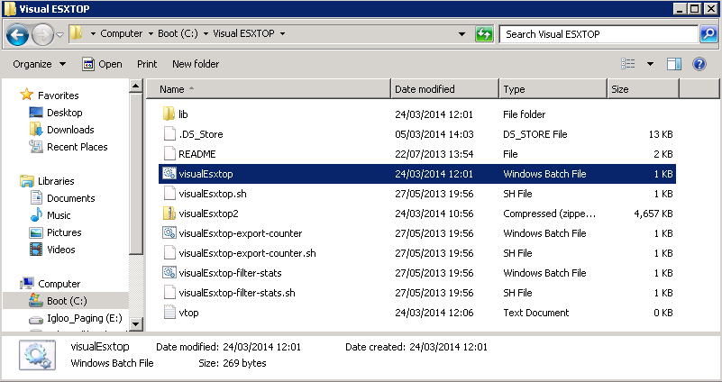
  • For Windows, navigate to your VisualEsxtop folder and run the VisualEsxtop.bat file

esxtop56

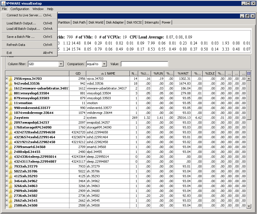
  • It should open the below application
  • Click File > Load Batch Output and open your CSV output file from running ESXTOP in Batch Mode

esxtop57

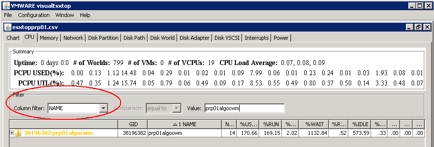
  • You can then filter as well

esxtop58

https://labs.vmware.com/flings/visualesxtop

http://blogs.vmware.com/kb/2013/09/using-visualesxtop-to-troubleshoot-performance-issues-in-vsphere-2.html

Perfmon

  • On your Windows Server, click Start > Run > Type perfmon
  • Right click on the graph and select “Properties”.

esxtop50

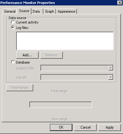
  • Select the “Source” tab.
  • Select the “Log files:” radio button from the “Data source” section.
  • Click the “Add” button.

esxtop51

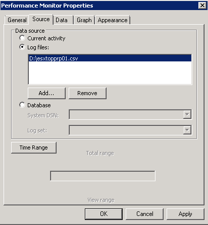
  • Select the CSV file created by esxtop and click “OK”.

esxtop52

  • Click the “Apply” button.
  • Optionally: reduce the range of time over which the data will be displayed by using the sliders under the “Time Range” button.
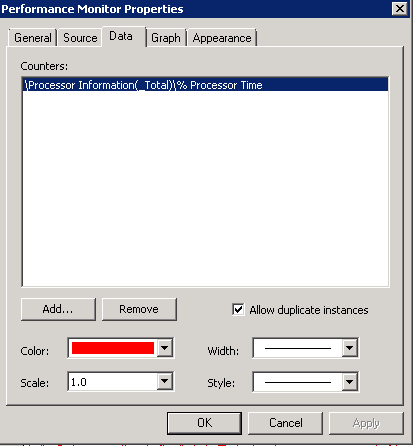
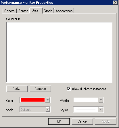
  • Select the “Data” tab.
  • Remove all Counters.

esxtop53

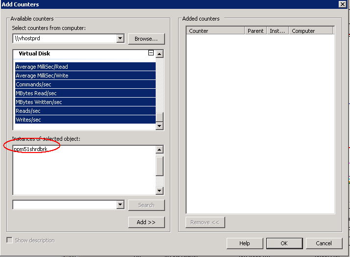
  • Click “Add” and select appropriate counters. When you click on some of the counters, you can select the instance or VM/Machine you want to monitor directly
  • Click Add

esxtop54

  • Click “OK”
  • Click “OK”
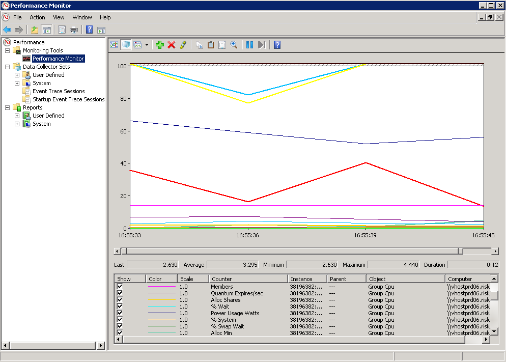
  • You should now see the graph of values

esxtop55

Using ESXPLOT

Please see the below link for instructions

  1. Run: esxplot
  2. Click File -> Import -> Dataset
  3. Select file and click “Open”
  4. Double click host name and click on metric

http://www.electricmonk.org.uk/2012/09/05/esxplot/

Using MS Excel

Within Excel it is also possible to import the data as a CSV. You need to be careful of the size of the file though as the amount of captured data is sometimes quite large so you might want to limit it by first importing it into perfmon and then select the correct timeframe and counters and export this to a CSV. You can import the CSV as per below instructions

  1. Run: Excel
  2. Click on “Data”
  3. Click “Import External Data” and click “Import Data”
  4. Select “Text files” as “Files of Type”
  5. Select file and click “Open”
  6. Make sure “Delimited” is selected and click “Next”
  7. Deselect “Tab” and select “Comma”
  8. Click “Next” and “Finish

Looking at esxtop values and results (Realtime)

General CPU Statistics

First visible CPU Statistics

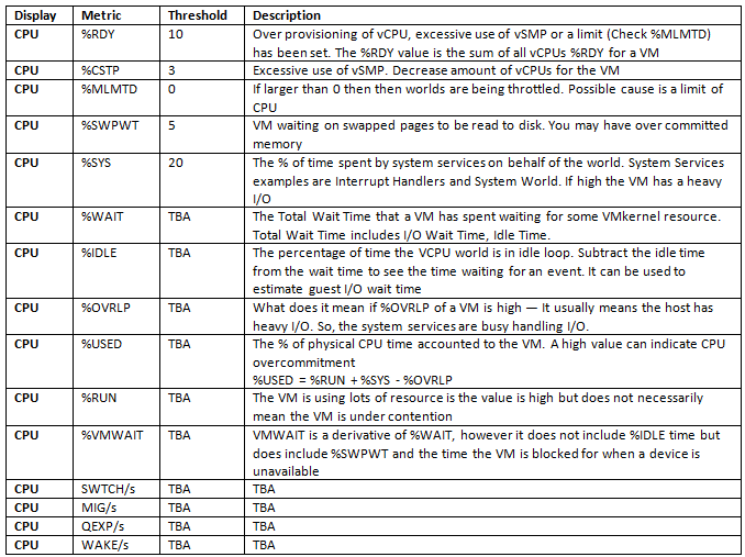
CPUesxtop

Optional Fields for CPU Performance Monitoring

General Memory Statistics

 First Visible Memory Statistics

esxtop5

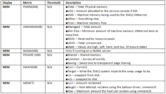
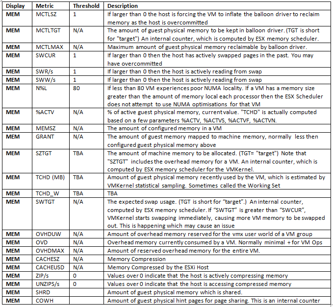
Optional Fields for Memory Performance Monitoring

esxtopmem5

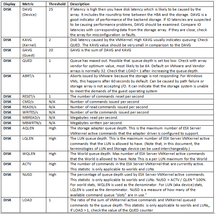
General Disk Statistics

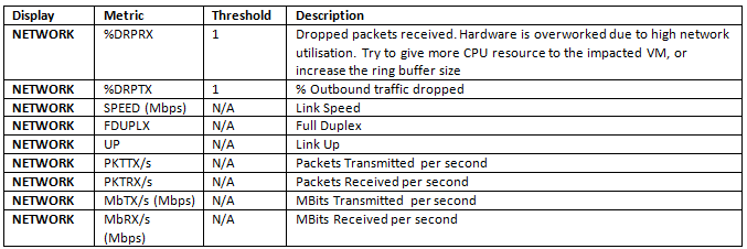
General Network Statistics

esxtopnetwork

Running ESXTOP in Replay Mode

In replay mode, esxtop replays resource utilization statistics collected using vm-support.

After you prepare for replay mode, you can use esxtop in this mode.

In replay mode, esxtop accepts the same set of interactive commands as in interactive mode and runs until no more snapshots are collected by vm-support to be read or until the requested number of iterations are completed.

To run in replay mode, you must prepare for replay mode.

  • Run vm-support in snapshot mode on the ESX service console
  • Type vm-support -S -d duration -I interval
  • -S = Snapshot mode, prompts for the delay between updates, in seconds
  • -R = Path to the vm-support collected snapshot’s directory
  • Unzip and untar the resulting tar file so that esxtop can use it in replay mode.
  • tar -xf /root/esx*.tgz
  • Now run the following
  • esxtop -R root/vm-support*

http://www.vmwarearena.com/2012/08/esxtop-replay-mode.html

5 of the best posts for analysing results and statistics

http://www.yellow-bricks.com/esxtop/

http://communities.vmware.com/docs/DOC-9279

http://www.vmware.com/pdf/esx2_using_esxtop.pdf

http://simongreaves.co.uk/blog/esxtop-guide

http://communities.vmware.com/docs/DOC-5240

Analysing CPU/RAM/Network/Performance

http://communities.vmware.com/docs/DOC-3930

Enhanced vMotion Compatibility

What is EVC?

EVC is short for Enhanced VMotion Compatibility. EVC allows you to migrate virtual machines between different generations of CPUs.

What is the benefit of EVC?

Because EVC allows you to migrate virtual machines between different generations of CPUs, with EVC you can mix older and newer server generations in the same cluster and be able to migrate virtual machines with VMotion between these hosts. This makes adding new hardware into your existing infrastructure easier and helps extend the value of your existing hosts. With EVC, full cluster upgrades can be achieved with no virtual machine downtime whatsoever. As you add new hosts to the cluster, you can migrate your virtual machines to the new hosts and retire the older hosts

How do I use EVC?

EVC is enabled for a cluster in the VirtualCenter or vCenter Server inventory. After it is enabled, EVC ensures that migration with VMotion is possible between any hosts in the cluster. Only hosts that preserve this property can be added to the cluster.

How does it work?

After EVC is enabled, all hosts in the cluster are configured to present the CPU features of a user-selected processor type to all virtual machines running in the cluster. This ensures CPU compatibility for VMotion even though the underlying hardware might be different from host to host. Identical CPU features are exposed to virtual machines regardless of which host they are running on, so that the virtual machines can migrate between any hosts in cluster

Which CPUs are compatible with each EVC mode?

To determine the EVC modes compatible with your CPU, search the VMware Compatibility Guide. Search for the server model or CPU family, and click the entry in the CPU Series column to display the compatible EVC modes.

Note: EVC is required for Fault Tolerant Machines to interoperate and integrate with DRS.

Instructions for enabling

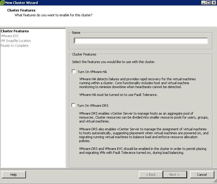
  • Right click on the Datacenter object in vCenter and select New Cluster
  • Type a name for the new cluster
  • Enable HA and DRS as you require

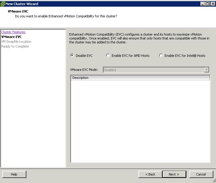
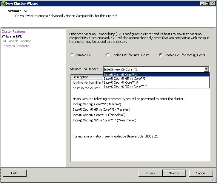
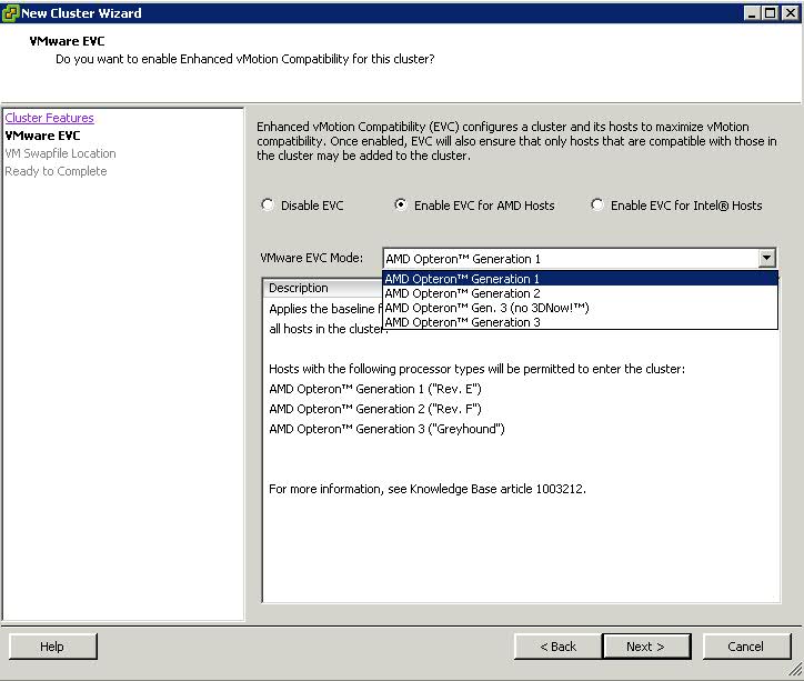
  • Select which EVC CPU Type you need

  • You then have to choose the processor mode you need. See below 2 diagrams

  • In order to know what mode to choose, please follow the below article

http://kb.vmware.com/kb/1003212

EVC and General Application Performance White Paper

http://www.vmware.com/files/pdf/techpaper/VMware-vSphere-EVC-Perf.pdf

Calculate Available Resources and VMware HA (High Availability) Slots

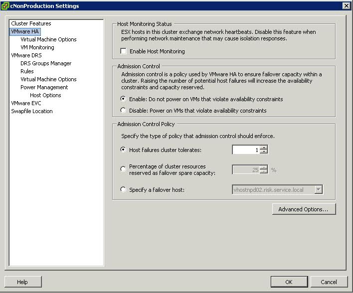
Admission Control Settings

Within a cluster we use Admission control to ensure that sufficient resources exist to provide failover protection. Admission control is also used to ensure that virtual machine resource reservations are protected

Admission Control Policies

  • Host Failures the Cluster tolerates
  • Percentage of Cluster Resources reserved as failover spare capacity
  • Specify Failover Hosts

Host Failures the Cluster tolerates

What is a Slot?

A slot is a logical representation of the memory and CPU resources that satisfy the requirements for any powered-on virtual machine in the cluster

In vCenter Server 4.0, the slot size is now shown in vSphere Client on the Summary tab of the cluster

How is the Slot calculated?

  • VMware HA determines how many slots are available in each ESX/ESXi host based on the host’s CPU and memory capacity.
  • It then determines how many ESX/ESXi hosts can fail in the cluster with at least as many slots as powered on virtual machines.

Default Reservation Values

Slot size is comprised of two components, CPU and memory

VMware calculates the memory component by obtaining the memory reservation (If set) plus memory overhead, of each powered-on virtual machine and selecting the largest value. There is no default value for the memory reservation.

If a virtual machine does not have reservations, meaning that the reservation is 0, default values are used as listed below

  • 0 MB of RAM and 256 MHz CPU speed are used for vSphere 4 and Prior
  • 0 MB of RAM and 32MHz for CPU for vSphere 5.0 and above
  • When no memory reservation is specified for a virtual machine, the largest memory overhead for any virtual machine in the cluster will be used as the default slot size value for memory

Advanced Settings for CPU and Memory Slot Size

  • das.vmMemoryMinMB <value>

This options/value pair overrides the default memory slot size value used for admission control for VMware HA where <value> is the amount of RAM in MB to be used for the calculation if there are no larger memory reservations. By default this value is set to 256MB. This is the minimum amount of memory in MB sufficient for any VM in the cluster to be usable

  • das.vmCPUMinMHz <value>

This options/value pair overrides the default CPU slot size value used for admission control for VMware HA where <value> is the amount of CPU in MHz to be used for the calculation if there are no larger memory reservations. By default this value is set to 256MHz

Maximum Upper Bound Advanced Settings for Slot Sizing

If your cluster contains any virtual machines that have much larger reservations than the others, they will  distort slot size calculation. To avoid this, you can specify an upper bound for the CPU or memory component of the slot size by using the das.slotcpuinmhz or das.slotmeminmb advanced attributes, respectively.

Keep in mind that when you are low on resources this could mean that you are not able to power-on this high reservation VM as resources are fragmented throughout the cluster instead of located on a single host.

  • das.slotmeminmb <value>

This option defines the maximum bound on the memory slot size. If this option is used, the slot size is the smaller of this value or the maximum memory reservation plus memory overhead of any powered-on virtual machine in the cluster.

  • das.slotcpuinmhz <value>

This option defines the maximum bound on the CPU slot size. If this option is used, the slot size is the smaller of this value or the maximum CPU reservation of any powered on virtual machine in the cluster

HA Failover Capacity

There are lots of questions surrounding VMware’s HA (High Availability), especially when users see a message stating there are “Insufficient resources to satisfy HA failover.” It is worth making the effort to understand capacity calculations. In current versions of ESX(i)and earlier, the following calculation applies for failover capacity.

Failover Capacity is determined using a slot size value that is calculated on the cluster. Slots are calculated by a combination of the total CPU and Memory that are in the physical hosts. The calculation for failover capacity works as follows:

Let’s say you have 4 ESX servers in your VMware HA cluster and Configured Failover capacity on the cluster is set to 1.

Physical memory in the hosts is as follows:

ESX1 = 16 GB
ESX2 = 24 GB
ESX3 = 32 GB
ESX4 = 32 GB

In the cluster you have 24 VM’s each configured and running. Of the 24 VM’s running, determine the VM which has the highest “configured memory”. For this example let’s say this is 2GB. All other VMs are configured with less or equal to 2GB.

With this information we can now do the calculation:

1. Pick the ESX host which has the least amount of RAM. In this case it is ESX1 and the minimum amount of RAM is = 16 GB

2. Divide the value found in step 1 with value for the maximum RAM in a VM. In my example this gives us 8 (16 divided by 2). This means we have 8 slots available per ESX host in the cluster.

3. Since we have 4 hosts and the configured failover capacity for the cluster is 1, we are left with 3 hosts in a failure situation. Hence the total number of VMs that can be powered on these 3 servers is 24 VMs. (i.e. 8 multiplied by 3 = 24)

4. If the total number of VMs in the cluster exceeds 24 then it will give us “Insufficient resources to satisfy HA failover” and the “current failover capacity will be shown as 0″. If the number is less than 24, we should not get this message.

Note: If you are still seeing the message and you have less VM’s running than in the calculation allows for, check both the CPU and Memory reservations on both VM’s and resource pools, as this can skew the calculation. You should avoid unnecessary memory or cpu reservations on VM’s as this can cause these types of errors to occur, because we have to ensure that the resource is available.

Host Failures?

What happens if you set the number of allowed host failures to 1?
The host with the most slots will be taken out of the equation. If you have 8 hosts with 90 slots in total but 7 hosts each have 10 slots and one host 20 this single host will not be taken into account. Worst case scenario! In other words the 7 hosts should be able to provide enough resources for the cluster when a failure of the “20 slot” host occurs.

And of course if you set it to 2 the next host that will be taken out of the equation is the host with the second most slots and so on

How can we get round distorted Slot Sizes causing HA errors?

There are multiple ways to fix, or get around this calculation. The most common are as follows:

  • Set the Disable – “ Power on Vms that violate availability constraints” in the configuration of the cluster. In this case it ignores the above calculation and will try to power on as many VM’s as possible in case of HA failover. If this is the option chosen you can also set restart priority in the ‘Virtual Machine Options’ section of the cluster configuration. This way any high priority VM’s are powered on first, and then the lower priority up to the point where we cannot power any further VM’s on

  • If you have one VM which is configured with a very high amount of memory, you can either lower its configured memory, or take it out of the cluster and run it on any other standalone ESX host. This will increase the number of slots available with the current hardware
  • Increase the amount of RAM on servers so that there are more slots available with the current RAM reservations.
  • Remove any CPU reservations on any VM(s) that are greater than the max speed of the processors in the hosts.
  • With vSphere this is something that’s configurable. If you have just one VM with a really high reservation you can set the following advanced settings to lower the slot size being used during these calculations: das.slotCpuInMHz or das.slotMemInMB. To avoid not being able to power on the VM with high reservations these VM will take up multiple slots. Keep in mind that when you are low on resources this could mean that you are not able to power-on this high reservation VM as resources are fragmented throughout the cluster instead of located on a single host.

What if you don’t want to…

  • Disable strict admission control
  • Mess around with setting advanced settings for Minimum Memory and CPU Slot size
  • Lower the VM Memory reservation

There is also the option of

  • Creating a memory reservation on a Resource Pool and putting the VM in here

Why?

High Availability ignores resource pools reservation settings when calculating the slot size, so if a single VM is placed in a resource pool with memory reservation configured, it will have the same effect on resource allocation as per VM memory reservation, but does not affect the HA slot size.

By creating a resource pool with a substantial memory setting you can avoid decreasing the consolidation ratio of the cluster and still guarantee the virtual machine its resources. You need to be careful though. Creating a Resource Pool for each VM would be a catastrophic way of managing multiple high memory configured VMs and probably should be carried out when you have 1 or 2 VMs that have this type of configuration

Percentage of Cluster Resources Reserved as Failover

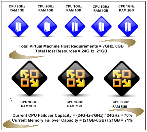
With the Percentage of Cluster Resources reserved for Failover Spare Capacity, vSphere HA ensures that a specified percentage of aggregate CPU and memory is reserved for Failover

vSphere HA uses reservations of CPU and Memory if they have been set. If not they use a default value of 0MB Memory and 256MHz CPU

With this policy HA does the following

  • Calculates the total resource requirement for all powered on machines in the cluster
  • Calculates the total host resources available for the virtual machines
  • Calculates the current CPU and Memory failover capacity for the cluster
  • Determines if either the current CPU failover or current memory failover is less than the corresponding failover capacity
  • If so Admission Control disallows the operation

Example

Specify Failover Hosts

If you choose this option, be aware that you will lose one whole host to be put aside for capcity

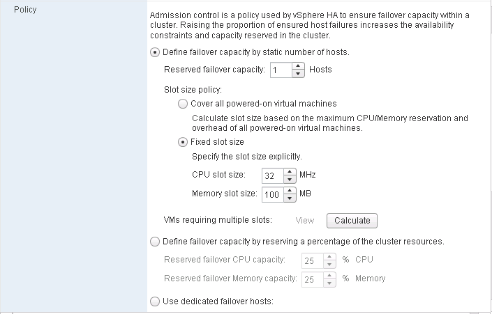
HA Slot sizes in the vSphere 5 Web Client

You now have the ability to set slot size for “Host failures tolerated” through the vSphere Web Client

slot

More Information

There are great articles on the below webpages regarding HA Slot sizing and calculation

http://www.vmwarewolf.com/ha-failover-capacity/#more

and this article walking you through an example

http://www.vladan.fr/ha-slot-sizes/

HA Slot sizes in the vSphere 5 Web Client

http://www.yellow-bricks.com/2012/09/12/whats-new-vsphere-5-1-high-availability/