Archive for Objective 2 Networking

Determine appropriate discovery protocol (CDP and LLDP)

silhouette

What are Switch Discovery Protocols

Switch discovery protocols allow vSphere administrators to determine which switch port is connected to a given vSphere standard switch or vSphere distributed switch.
vSphere 5.0 supports

  • Cisco Discovery Protocol (CDP) CDP is available for vSphere standard switches and vSphere distributed switches connected to Cisco physical switches.
  • Link Layer Discovery Protocol (LLDP). LLDP is available for vSphere distributed switches version 5.0.0 and later and is vendor neutral

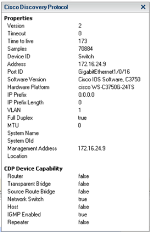
When CDP or LLDP is enabled for a particular vSphere distributed switch or vSphere standard switch, you can view properties of the peer physical switch such as

  • Device ID
  • Software version
  • Timeout from the vSphere Client

Enable Cisco Discovery Protocol on a vSphere Distributed Switch

Cisco Discovery Protocol (CDP) allows vSphere administrators to determine which Cisco switch port connects to a given vSphere standard switch or vSphere distributed switch. When CDP is enabled for a particular vSphere distributed switch, you can view properties of the Cisco switch (such as device ID, software version, and timeout) from the vSphere Client.

Procedure

  • Log in to the vSphere Client and select the Networking inventory view
  • Right-click the vSphere distributed switch in the inventory pane, and select Edit Settings
  • On the Properties tab, select Advanced
  • Select Enabled from the Status drop-down menu
  • Select Cisco Discovery Protocol from the Type drop-down menu.
  • Select the CDP mode from the Operation drop-down menu.

cdp2

  • Operation options are described below

DISCOVERY

Enable LLDP Discovery Protocol on a vSphere Distributed Switch

With Link Layer Discovery Protocol (LLDP), vSphere administrators can determine which physical switch port connects to a given vSphere distributed switch. When LLDP is enabled for a particular distributed switch, you can view properties of the physical switch (such as chassis ID, system name and description, and device capabilities) from the vSphere Client. LLDP is available only on vSphere distributed switch version 5.0.0 and later. It supports the standards based discovery protocol IEE 802.1AB

Procedure

  • Log in to the vSphere Client and select the Networking inventory view.
  • Right-click the vSphere distributed switch in the inventory pane, and select Edit Settings.
  • On the Properties tab, select Advanced.
  • Select Enabled from the Status drop-down menu.
  • Select Link Layer Discovery Protocol from the Type drop-down menu.

cdp2

  • Select the LLDP mode from the Operation drop-down menu.

DISCOVERY

View Switch Information on the vSphere Client

When CDP or LLDP is set to Listen or Both, you can view physical switch information from the vSphere Client.

Procedure

  • Log in to the vSphere Client and select the host from the inventory panel.
  • Click the Configuration tab and click Networking.
  • Click the information icon to the right of the vSphere standard switch or vSphere distributed switch to display information for that switch.
  • Switch information for the selected switch appears.

VMWARE

Configure vSS and vDS Settings Using Command Line Tools

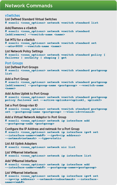
images

Valid Commands

Note: With the release of 5.0 and 5.1, the majority of the legacy esxcfg-*/vicfg-* commands have been migrated over to esxcli. At some point, hopefully not in the distant future, esxcli will be parity complete and the esxcfg-*/vicfg-* commands will be completely deprecated and removed including the esxupdate/vihostupdate utilities.

  • esxcfg-nics
  • vicfg-nics
  • esxcfg-route
  • vicfg-route
  • esxcfg-vmknic
  • vicfg-vmknic
  • esxcfg-vswitch
  • vicfg-vswitch
  • esxcli network nic
  • esxcli network interface
  • esxcli network vswitch
  • esxcli network ip

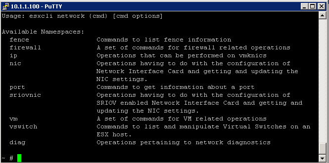
ESXCLI Network Namespaces

http://pubs.vmware.com

network 2

networkin

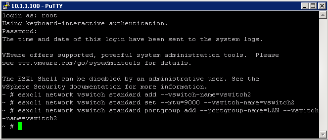
ESXCLI Network Namespace Examples

NETWORK

vCLI Poster of example commands

http://blogs.vmware.com

Migrate a vSS network to a Hybrid or vDS Solution

lightswitch

Hybrid vSS/vDS/Nexus Virtual Switch Environments

Each ESX host can concurrently operate a mixture of virtual switches as follows:

  • One or more vNetwork Standard Switches
  • One or more vNetwork Distributed Switches
  • A maximum of one Cisco Nexus 1000V (VEM or Virtual Ethernet Module).

Note that physical NICs (vmnics) cannot be shared between virtual switches (i.e. each vmnic only be assigned to one switch at any one time)

Examples of Distributed switch configurations

Single vDS

Migrating the entire vSS environment to a single vDS represents the simplest deployment and administration model as per below picture. All VM networking plus VMkernel and service console ports are migrated to the vDS. The NIC teaming policies configured on the DV Port Groups can isolate and direct traffic down the appropriate dvUplinks (which map to individual vmnics on each host)

singlevds

Hybrid vDS and vSS

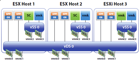
The picture below shows an example environment where the VM networking is migrated to a vDS, but the Service Console and VMkernel ports remain on a vSS. This scenario might be preferred for some environments where the NIC teaming policies for the VMs are isolated
from those of the VMkernel and Service Console ports. For example, in the picture, the vmnics and VM networks on vSS-1 could be migrated to vDS-0 while vSS-0 could remain intact and in place.
In this scenario, VMs can still take advantage of Network VMotion as they are located on dv Port Groups on the vDS.

vdsandvss

Multiple vDS

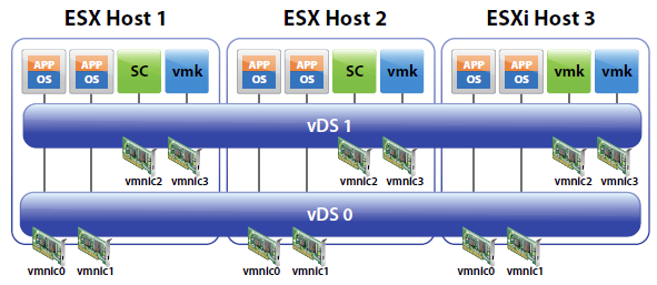
Hosts can be added to multiple vDS’s as shown below (Two are shown, but more could be added, with or without vmnic to dvUplink assignments). This configuration might be used to:

  • Retain traffic separation when attached to access ports on physical switches (i.e. no VLAN tagging and switchports are assigned to a single VLAN).
  • Retain switch separation but use advanced vDS features for all ports and traffic types.

HYBRID

Planning the Migration to vDS

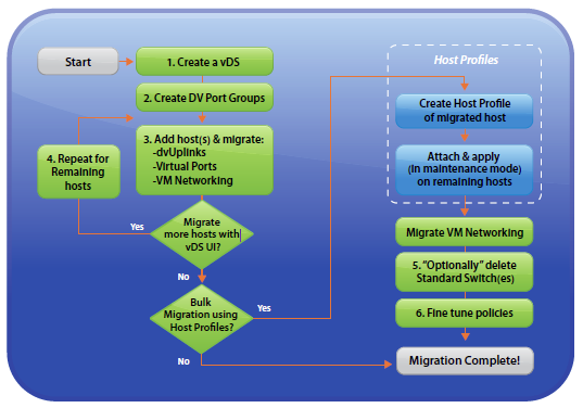
Migration from a vNetwork Standard Switch only environment to one featuring one or more vNetwork Distributed Switches can be accomplished in either of two ways:

  • Using only the vDS User Interface (vDS UI) — Hosts are migrated one by one by following the New vNetwork Distributed Switch process under the Home > Inventory > Network view of the Datacenter from the vSphere Client.
  • Using a combination of the vDS UI and Host Profiles— The first host is migrated to vDS and the remaining hosts are migrated to vDS using a Host Profile of the first host.

High Level Overview

The steps involved in a vDS UI migration of an existing environment using Standard Switches to a vDS are as follows:

  • Create vDS (without any associated hosts)
  • Create Distributed Virtual Port Groups on vDS to match existing or required environment
  • Add host to vDS and migrate vmnics to dvUplinks and Virtual Ports to DV Port Groups
  • Repeat Step 3 for remaining hosts

SWITCHACTION

Create a vSphere Distributed Switch

If you have decided that you need to perform a vSS to vDS migration, a vDS needs to be created first.

  1. From the vSphere Client, connect to vCenter Server.
  2. Navigate to Home > Inventory > Networking (Ctrl+Shift+N)
  3. Highlight the datacenter in which the vDS will be created.
  4. With the Summary tab selected, under Commands, click New vSphere Distributed Switch
  5. On the Switch Version screen, select the appropriate vDS version, ie 5.0.0, click Next.
  6. On the General Properties screen, enter a name and select the number of uplink ports, click Next.
  7. On the Add Hosts and Physical Adapters screen, select Add later, click Next.
  8. On the Completion screen, ensure that Automatically create a default port group is selected, click Finish.
  9. Verify that the vDS and associated port group were created successfully.

Create DV Port Groups

You now need to create vDS port groups. Port groups should be created for each of the traffic types in your environment such as VM traffic, iSCSI, FT, Management and vMotion traffic, as required.

  1. From the vSphere Client, connect to vCenter Server.
  2. Navigate to Home > Inventory > Networking (Ctrl+Shift+N).
  3. Highlight the vDS created in the previous section.
  4. Under Commands, click New Port Group.
  5. On the Properties screen, enter an appropriate Name, ie IPStorage, Number of Ports and VLAN type and ID (if required), click Next. Note: If the port group is associated with a VLAN, it’s recommended to include the VLAN ID in the port group name
  6. On the completion screen, verify the port group settings, click Finish.
  7. Repeat steps for all required port groups.

Add ESXi Host(s) to vSphere Distributed Switch

After successfully creating a vDS and configuring the required port groups, we now need to add an ESXi host to the vDS.

  1. From the vSphere Client, connect to vCenter Server.
  2. Navigate to Home > Inventory > Networking (Ctrl+Shift+N).
  3. Highlight the vDS created previously.
  4. Under Commands, click Add Host.
  5. On the Select Hosts and Physical Adapters screen, select the appropriate host(s) and any physical adapters (uplinks) which are not currently in use on your vSS, click Next. Note: Depending on the number of physical NIC’s in your host, it’s a good idea to leave at least 1 connected to the vSS until the migration is complete. This is particularly relevant if your vCenter Server is a VM.
  6. On the Network Connectivity screen, migrate virtual NICs as required, selecting the associated destination port group on the vDS, click Next.
  7. On the Virtual Machine Networking screen, click Migrate virtual machine networking. Select the VMs to be migrated and the appropriate destination port group(s), click Next..
  8. On the Completion screen, verify your settings, click Finish.
  9. Ensure that the task completes successfully.

Migrate Existing Virtual Adapters (vmkernel ports).

  1. From the vSphere Client, connect to vCenter Server.
  2. Navigate to Home > Inventory > Hosts and Clusters (Ctrl+Shift+H).
  3. Select the appropriate ESXi host, click Configuration > Networking (Hardware) > vSphere Distributed Switch.
  4. Click Manage Virtual Adapters.
  5. On the Manage Virtual Adapters screen, click Add.
  6. On the Creation Type screen, select Migrate existing virtual adapters, click Next.
  7. On the Network Connectivity screen, select the appropriate virtual adapter(s) and destination port group(s), Click Next.
  8. On the Ready to Complete screen, verify the dvSwitch settings, click Finish.

Create New Virtual Adapters (vmkernel ports)

Perform the following steps to create new virtual adapters for any new port groups which were created previously.

  1. From the vSphere Client, connect to vCenter Server.
  2. Navigate to Home > Inventory > Hosts and Clusters (Ctrl+Shift+H).
  3. Select the appropriate ESXi host, click Configuration > Networking (Hardware) > vSphere Distributed Switch.
  4. Click Manage Virtual Adapters.
  5. On the Manage Virtual Adapters screen, click Add.
  6. On the Creation Type screen, select New virtual adapter, click Next.
  7. On the Virtual Adapter Type screen, ensure that VMkernel is selected, click Next.
  8. On the Connection Settings screen, ensure that Select port group is selected. Click the dropdown and select the appropriate port group, ie VMotion. Click Use this virtual adapter for vMotion, click Next.
  9. On the VMkernel – IP Connection Settings screen, ensure that Use the following IP settings is selected. Input IP settings appropriate for your environment, click Next.
  10. On the Completion screen, verify your settings, click Finish.
  11. Repeat for remaining virtual adapters, as required.

Migrate Remaining VMs

Follow the steps below to migrate any VMs which remain on your vSS.

  1. From the vSphere Client, connect to vCenter Server.
  2. Navigate to Home > Inventory > Hosts and Clusters (Ctrl+Shift+H).
  3. Right-click the appropriate VM, click Edit Settings.
  4. With the Hardware tab selected, highlight the network adapter. Under Network Connection, click the dropdown associated with Network label. Select the appropriate port group, ie VMTraffic (dvSwitch). Click OK.
  5. Ensure the task completes successfully.
  6. Repeat for any remaining VMs.

Migrate Remaining Uplinks

It’s always a good idea to leave a physical adapter or 2 connected to the vSS, especially when your vCenter Server is a VM. Migrating the management network can sometimes cause issues. Assuming all your VM’s have been migrated at this point, perform the following steps to migrate any remaining physical adapters (uplinks) to the newly created vSS.

  1. From the vSphere Client, connect to vCenter Server.
  2. Navigate to Home > Inventory > Hosts and Clusters (Ctrl+Shift+H).
  3. Select the appropriate ESXi host, click Configuration > Networking (Hardware) > vSphere Distributed Switch.
  4. Click Manage Physical Adapters.
  5. Click Click to Add NIC within the DVUplinks port group.
  6. Select the appropriate physical adapter, click OK.
  7. Click Yes on the remove and reconnect screen.
  8. Click OK.
  9. Ensure that the task completes successfully.
  10. Repeat for any remaining physical adapters

Identify common virtual switch configurations

images

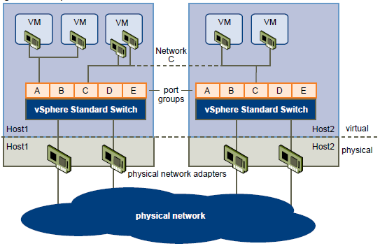
vSphere Standard Switch Architecture

You can create abstracted network devices called vSphere standard switches. A standard switch can..

  1. Route traffic internally between virtual machines and link to external networks
  2. Combine the bandwidth of multiple network adaptors and balance communications traffic among them.
  3. Handle physical NIC failover.
  4. Have a default number of logical ports which for a standard switch is 120. You can
  5. Connect one network adapter of a virtual machine to each port. Each uplink adapter associated with a standard switch uses one port.
  6. Each logical port on the standard switch is a member of a single port group.
  7. Have one or more port groups assigned to it.
  8. When two or more virtual machines are connected to the same standard switch, network traffic between them is routed locally. If an uplink adapter is attached to the standard switch, each virtual machine can access the external network that the adapter is connected to.
  9. vSphere standard switch settings control switch-wide defaults for ports, which can be overridden by port group settings for each standard switch. You can edit standard switch properties, such as the uplink configuration and the number of available ports.

Standard Switch

standardswitch

vSphere Distributed Switch Architecture

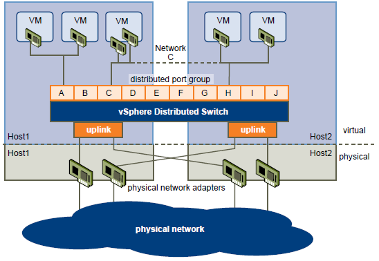
A vSphere distributed switch functions as a single switch across all associated hosts. This enables you to set network configurations that span across all member hosts, and allows virtual machines to maintain consistent network configuration as they migrate across multiple hosts

Like a vSphere standard switch, each vSphere distributed switch is a network hub that virtual machines can use.

  • Enterprise Plus Licensed feature only
  • VMware vCenter owns the configuration of the distributed switch
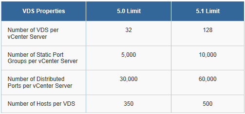
  • Distributed switches can support up to 350 hosts
  • You configure a Distributed switch on vCenter rather than individually on each host
  • Provides support for Private VLANs
  • Enable networking statistics and policies to migrate with VMs during vMotion
  • A distributed switch can forward traffic internally between virtual machines or link to an external network by connecting to physical Ethernet adapters, also known as uplink adapters.
  • Each distributed switch can also have one or more distributed port groups assigned to it.
  • Distributed port groups group multiple ports under a common configuration and provide a stable anchor point for virtual machines connecting to labeled networks.
  • Each distributed port group is identified by a network label, which is unique to the current datacenter. A VLAN ID, which restricts port group traffic to a logical Ethernet segment within the physical network, is optional.
  • Network resource pools allow you to manage network traffic by type of network traffic.
  • In addition to vSphere distributed switches, vSphere 5 also provides support for third-party virtual switches.

vdsswitch

TCP/IP Stack at the VMkernel Level

The VMware VMkernel TCP/IP networking stack provides networking support in multiple ways for each of the services it handles.

The VMkernel TCP/IP stack handles iSCSI, NFS, and vMotion in the following ways for both Standard and Distributed Virtual Switches

  • iSCSI as a virtual machine datastore
  • iSCSI for the direct mounting of .ISO files, which are presented as CD-ROMs to virtual machines.
  • NFS as a virtual machine datastore.
  • NFS for the direct mounting of .ISO files, which are presented as CD-ROMs to virtual machines.
  • Migration with vMotion.
  • Fault Tolerance logging.
  • Port-binding for vMotion interfaces.
  • Provides networking information to dependent hardware iSCSI adapters.
  • If you have two or more physical NICs for iSCSI, you can create multiple paths for the software iSCSI by configuring iSCSI Multipathing.

Networking Policies

Policies set at the standard switch or distributed port group level apply to all of the port groups on the standard switch or to ports in the distributed port group. The exceptions are the configuration options that are overridden at the standard port group or distributed port level.

  • Load Balancing and Failover Policy
  • VLAN Policy
  • Security Policy
  • Traffic Shaping Policy
  • Resource Allocation Policy
  • Monitoring Policy
  • Port Blocking Policies
  • Manage Policies for Multiple Port Groups on a vSphere Distributed Switch

Networking Best Practices

  • Separate network services from one another to achieve greater security and better performance. Put a set of virtual machines on a separate physical NIC. This separation allows for a portion of the total networking workload to be shared evenly across multiple CPUs. The isolated virtual machines can then better serve traffic from a Web client, for example
  • Keep the vMotion connection on a separate network devoted to vMotion. When migration with vMotion occurs, the contents of the guest operating system’s memory is transmitted over the network. You can do this either by using VLANs to segment a single physical network or by using separate physical networks (the latter is preferable).
  • When using passthrough devices with a Linux kernel version 2.6.20 or earlier, avoid MSI and MSI-X modes because these modes have significant performance impact.
  • To physically separate network services and to dedicate a particular set of NICs to a specific network service, create a vSphere standard switch or vSphere distributed switch for each service. If this is not possible, separate network services on a single switch by attaching them to port groups with different VLAN IDs. In either case, confirm with your network administrator that the networks or VLANs you choose are isolated in the rest of your environment and that no routers connect them.
  • You can add and remove network adapters from a standard or distributed switch without affecting the virtual machines or the network service that is running behind that switch. If you remove all the running hardware, the virtual machines can still communicate among themselves. If you leave one network adapter intact, all the virtual machines can still connect with the physical network.
  • To protect your most sensitive virtual machines, deploy firewalls in virtual machines that route between virtual networks with uplinks to physical networks and pure virtual networks with no uplinks.
  • For best performance, use vmxnet3 virtual NICs.
  • Every physical network adapter connected to the same vSphere standard switch or vSphere distributed switch should also be connected to the same physical network.
  • Configure all VMkernel network adapters to the same MTU. When several VMkernel network adapters are connected to vSphere distributed switches but have different MTUs configured, you might experience network connectivity problems.

How Many NIC Ports should I use?

Whether you are purchasing new servers or trying to reuse existing servers you need to determine how many NIC ports you want/need and what speed NIC’S; 10GB, 1GB, fibre, etc. I would try and install as many NICs as possible and combine NIC ports across switches

  • Redundancy

You want to be able to remove all single points of failure in your network.  You can team NIC’S together to achieve redundancy and use Link Aggregration or Etherchannel to compliment this on your physical switches

  • Throughput

The speed of your NICs is extremely important depending on the amount of network traffic you anticipate creating on your networks. NFS is a consideration along with backup and replication traffic, let alone normal network traffic.

  • Flexibility

You can provision more NIC’s as demand for certain services increase or decrease.

NIC Considerations

  • Jumbo Frames
  • TOE (TCP Offload Engine)
  • Boot from SAN
  • iSCSI or Fibre
  • 1GB, 10GB ethernet or Fibre

Data Plane and Control Planes

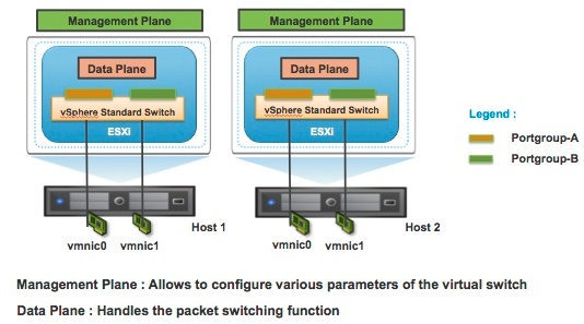
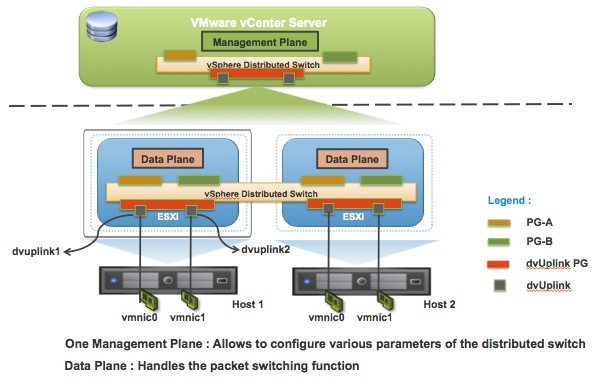
vSphere network switches can be broken into two logical sections. These are the data plane and the management plane.

  • The data plane implements the actual packet switching, filtering, tagging, etc.
  • The management plane is the control structure used to allow the operator to configure the data plane functionality.
  • With the vSphere Standard Switch (VSS), the data plane and management plane are each present on each standard switch. In this design, the administrator configures and maintains each VSS on an individual basis.

Virtual Standard Switch Control and Data Plane

Planes

With the release of vSphere 4.0, VMware introduced the vSphere Distributed Switch. VDS eases the management burden of per host virtual switch configuration by treating the network as an aggregated resource. Individual host-level virtual switches are abstracted into a single large VDS that spans multiple hosts at the Datacenter level. In this design, the data plane remains local to each VDS, but the management plane is centralized with vCenter Server acting as the control point for all configured VDS instances.

Virtual Distributed Switch Control and Data Plane

planes2

Limits

switchlimits

Configure SNMP on VMware

What is SNMP?

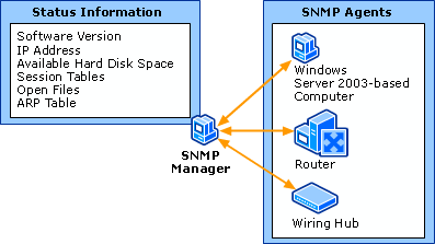
Simple Network Management Protocol (SNMP) is an “Internet-standard protocol for managing devices on IP networks.” Devices that typically support SNMP include routers, switches, servers, workstations, printers, modem racks, and more.” It is used mostly in network management systems to monitor network-attached devices for conditions that warrant administrative attention. SNMP is a component of the Internet Protocol Suite as defined by the Internet Engineering Task Force (IETF). It consists of a set of standards for network management, including an application layer protocol, a database schema, and a set of data objects.

SNMP exposes management data in the form of variables on the managed systems, which describe the system configuration. These variables can then be queried (and sometimes set) by managing application

SNMP

SNMP Agents

vCenter Server and ESXi systems include different SNMP agents.

  • vCenter Server SNMP agent

The SNMP agent included with vCenter Server can send traps when the vCenter Server system is started or when an alarm is triggered on vCenter Server. The vCenter Server SNMP agent functions only as a trap emitter and does not support other SNMP operations (for example, GET).

You can manage the vCenter Server agent with the vSphere Client or the vSphere Web Client but not with the vCLI command.

  • Host-based embedded SNMP agent

ESXi 4.0 and later includes an SNMP agent embedded in the host daemon (hostd) that can send traps and receive polling requests such as GET requests.
You can manage SNMP on ESXi hosts with the vicfg-snmp vCLI command or with the ESXCLI command in 5.1

  • Net-SNMP-based agent

Versions of ESX released before ESX/ESXi 4.0 include a Net-SNMP-based agent. You can continue to use this Net-SNMP-based agent in ESX 4.x with MIBs supplied by your hardware vendor and other third-party management applications. However, to use the VMware MIB files, you must use the host-based embedded SNMP agent.

 Configure SNMP Settings on a vCenter Server

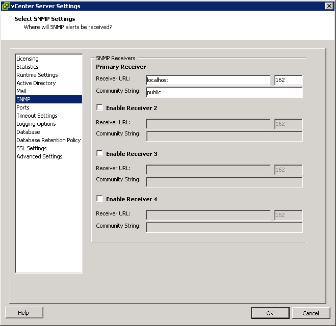
You can configure up to four receivers to receive SNMP traps from vCenter Server. For each receiver, specify a host name, port, and community.

  • If necessary, select Administration > vCenter Server Settings to display the vCenter Server Settings dialog box.
  • If the vCenter Server system is part of a connected group, select the server you want to configure from the Current vCenter Server drop-down menu.
  • In the settings list, select SNMP.
  • In Receiver URL, enter the host name or IP address of the SNMP receiver.
  • In the field next to the Receiver URL field, enter the port number of the receiver.
  • The port number must be a value between 1 and 65535.
  • In Community, enter the community identifier.

snmp

Configure SNMP for ESXi

ESXi includes an SNMP agent that can

  • Send notifications (traps and informs)
  • Receive GET, GETBULK, and GETNEXT requests

In ESXi 5.1 and later releases, the SNMP agent adds support for version 3 of the SNMP protocol, offering increased security and improved functionality, including the ability to send informs. You can use esxcli commands to enable and configure the SNMP agent. You configure the agent differently depending on whether you want to use SNMP v1/v2c or SNMP v3.

As an alternative to configuring SNMP manually using esxcli commands, you can use host profiles to configure SNMP for an ESXi host.

Procedure

  • Configure SNMP Communities.

Configure the SNMP Agent. You have the following 2 choices:

  • Configuring the SNMP Agent to Send Traps
  • Configuring the SNMP Agent for Polling

Instructions for Sending Traps

  • Configure at least one community for the agent

An SNMP community defines a group of devices and management systems. Only devices and management systems that are members of the same community can exchange SNMP messages. A device or management system can be a member of multiple communities. In the example below you can see Public and Internal

  • Log into vMA
  • Type vifp addserver
  • Type vifptarget -s
  • Type vicfg-snmp -c public,Internal for each Host that you have.

snmp1

  • Each time you specify a community with this command, the settings that you specify overwrite the previous configuration.
  • Next configure the SNMP Agent to Send Traps

You can use the SNMP agent embedded in ESXi to send virtual machine and environmental traps to management systems. To configure the agent to send traps, you must specify a target (receiver) address, the community, and an optional port. If you do not specify a port, the SNMP agent sends traps to UDP port 162 on the target management system by default

Each time you specify a target with this command, the settings you specify overwrite all previously specified settings. To specify multiple targets, separate them with a comma.
You can change the port that the SNMP agent sends data to on the target using the -t option. That port is UDP 162 by default

  • Enable the SNMP agent if it is not yet running.
  • vicfg-snmp -E
  • (Optional) Send a test trap to verify that the agent is configured correctly.
  • vicfg-snmp <conn_options> –test

Instructions for Polling

  • Configure at least one community for the agent

An SNMP community defines a group of devices and management systems. Only devices and management systems that are members of the same community can exchange SNMP messages. A device or management system can be a member of multiple communities.

  • Type vicfg-snmp -c public, internal
  • Each time you specify a community with this command, the settings that you specify overwrite the previous configuration
  • (Optional) Specify a port for listening for polling requests
  • vicfg-snmp <conn_options> -p 162
  • (Optional) If the SNMP agent is not enabled, enable it
  • vicfg-snmp -E
  • Run vicfg-snmp -T to validate the configuration.

The following example shows how the commands are run in sequence.

  • vicfg-snmp <conn_options> –c public –t example.com@162/private -E
  • next validate your config by doing these things
  • vicfg-snmp <conn_options> -T
  • walk –v1 –c public esx-host

SNMP Diagnostics

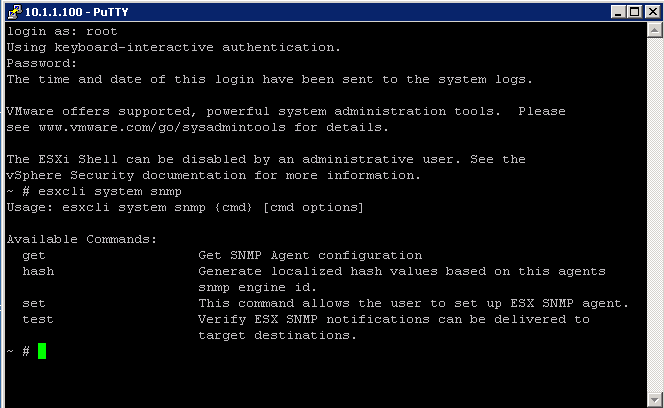
  • Type esxcli system snmp test to prompt the SNMP agent to send a test warmStart trap.
  • Type esxcli system snmp get to display the current configuration of the SNMP agent.

Configure SNMP Management Client Software

After you have configured a vCenter Server system or an ESXi host to send traps, you must configure your management client software to receive and interpret those traps.

To configure your management client software

  • Specify the communities for the managed device
  • Configure the port settings
  • Load the VMware MIB files. See the documentation for your management system for specific instructions for these steps.

Instructions

  • Download the VMware MIB files from the VMware Web site: http://communities.vmware.com/community/developer/managementapi.
  • In your management software, specify the vCenter Server or ESXi host as an SNMP-based managed device.
  • If you are using SNMP v1 or v2c, set up appropriate community names in the management software.
  • These names must correspond to the communities set for the SNMP agent on the vCenter Server system or ESXi host.
  • If you are using SNMP v3, configure users and authentication and privacy protocols to match those configured on the ESXi host.
  • If you configured the SNMP agent to send traps to a port on the management system other than the default UDP port 162, configure the management client software to listen on the port you configured.
  • Load the VMware MIBs into the management software so you can view the symbolic names for the vCenter Server or host variables.
  • To prevent lookup errors, load these MIB files in the following order before loading other MIB files:

VMWARE-ROOT-MIB.mib
VMWARE-TC-MIB.mib
VMWARE-PRODUCTS-MIB.mib

  • The management software can now receive and interpret traps from vCenter Server or ESXi hosts.

ESXCLI in vSphere 5 for managing SNMP

You can also now use ESXCLI commands to set up and manage SNMP as per below screenprints

snmp esxcli

Determine use cases for and configure VMware DirectPath I/O

pci

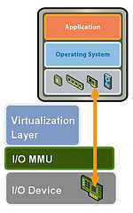
DirectPath I/O allows virtual machine access to physical PCI functions on platforms with an I/O Memory Management Unit.

The following features are unavailable for virtual machines configured with DirectPath

  • Hot adding and removing of virtual devices
  • Suspend and resume
  • Record and replay
  • Fault tolerance
  • High availability
  • DRS (limited availability. The virtual machine can be part of a cluster, but cannot migrate across hosts)
  •  Snapshots

Cisco Unified Computing Systems (UCS) through Cisco Virtual Machine Fabric Extender (VM-FEX) distributed switches support the following features for migration and resource management of virtual machines which use DirectPath I/O

  • Hot adding and removing of virtual devices
  • vMotion
  • Suspend and resume
  • High availability
  • DRS (limited availability
  •  Snapshots

Configure Passthrough Devices on a Host

  • Click on a Host
  • Select the Configuration Tab
  • Under Hardware, select Advanced Settings. You will see a warning message as per below

pass

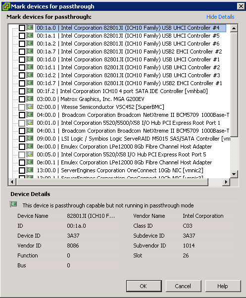
  • Click Configure Passthrough. The Passthrough Configuration page appears, listing all available passthrough devices.

passthrough

  • A green icon indicates that a device is enabled and active. An orange icon indicates that the state of the device has changed and the host must be rebooted before the device can be used

Capture

Configure a PCI Device on a VM

Prerequisites

Verify that a Passthrough networking device is configured on the host of the virtual machine as per above instructions

Instructions

  • Select a VM
  • Power off the VM
  • From the Inventory menu, select Virtual Machine > Edit Settings
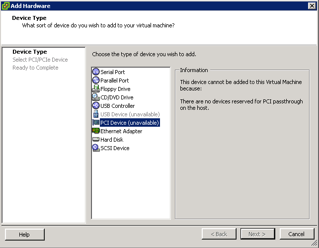
  • On the Hardware tab, click Add.
  • Select PCI Device and click Next
  • Select the Passthrough device to use
  • Click Finish
  • Power on VM

As per below I haven’t cofigured any pass thorugh devices but just to show you where the settings are

vmpci


VMware Netflow Monitoring

What is Netflow?

It’s a Cisco protocol that was developed for analysing network traffic. It has become an industry standard spec for collecting types of network data for monitoring and reporting. Data sources being switches and routers etc

  • A network Analysis Tool for monitoring the network and for gaining visibility into VM Traffic
  • A tool that can be used for profiling, intrusion detection, networking forensics and compliance
  • Supported on Distributed Virtual Switches in vSphere 5
  • Sarbanes Oxley compliance
  • Not really for packet sniffing,more for profiling the top 10 network flows etc

How is it implemented?

It is implemented in vSphere 5 dvSwitches

What types of flow does Netflow capture?

  • Internal Flow. Represents intrahost virtual machine traffic. Traffic between VM’s on the same host
  • External Flow. Represents interhost virtual machine traffic and physical machine to virtual machine traffic. Traffic between VM’s on different hosts or VM’s on different switches

What is a flow?

A flow is a sequence of packets that share the same 7 properties

  1. Source IP Address
  2. Destination IP Address
  3. Source Port
  4. Destination Port
  5. Input Interface ID
  6. Output interface ID
  7. Protocol

Flows

A flow is unidirectional. Flows are processed and stored as flow records by supported network devices such as dvSwitches. The flow records are then sent to a NetFlow Collector for additional analysis.

Although efficient, NetFlow can put an additional strain on your network or the dvSwitch as it requires extra processing and additional storage on the host for the flow records to be processed and exported.

Third Party NetFlow Collectors – What do they do?

Third Party vendors have NetFlow Collector Products which can include the following features

  • Accepts and stores network flow records
  • Includes a storage system for long term storage on flow based data
  • Mines, aggregates and reports on the collected data
  • Customised user interface (Web based usually)

Reporting

The Netflow Collector reports on various kinds of networking information including

  1. Top network or bandwidth flows
  2. The IP Addresses which are behaving irregularly
  3. The number of bytes a VM has sent and received in the past 24 hours
  4. Unexpected application traffic

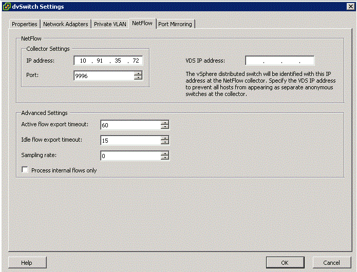
Configuring Netflow

  1. Go to Networking Inventory View
  2. Select dvSwitch and Edit Settings
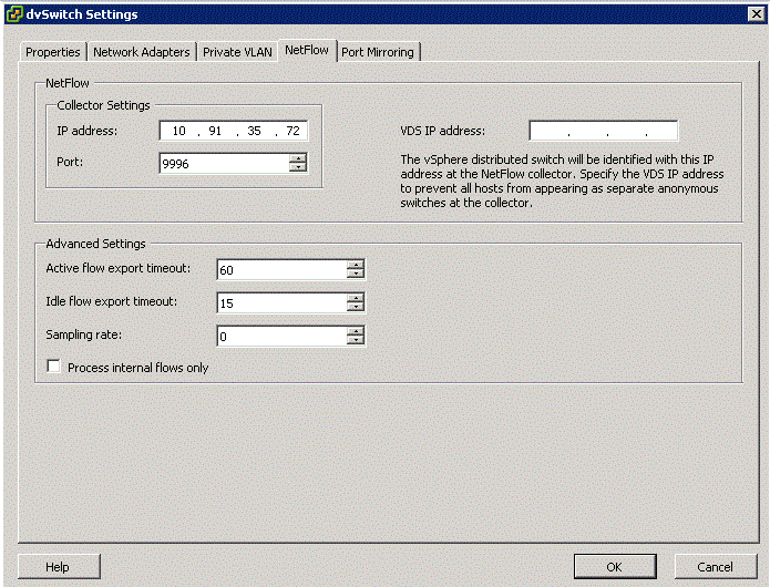
  3. Click Netflow tab to see the box above

Description of options

  • Collector IP Address and Port

The IP Address and Port number used to communicate with the Netflow collector system. These fields must be set for Netflow Monitoring to be enabled for the dvSwitch or for any port or port group on the dvSwitch

  • VDS IP Address

An optional IP Address which is used to identify the source of the network flow to the NetFlow collector. The IP Address is not associated with a network port and it does not need to be pingable. This IP Address is used to fill the Source IP of the NetFlow packets. This IP Address allows the Netflow collector to interact with the dvSwitch as a single switch, rather than seeing a separate unrelated switch for each associated host. If this is not configured, the hosts management address is used instead.

  • Active flow export timeout

The number of seconds after which active flows (flows where packets are sent) are forced to be exported to the NetFlow collector. The default is 300 and can range from 0-3600

  • Idle flow export timeout

The The number of seconds after which idle flows (flows where no packets have been seen for x number of seconds) are forced to be exported to the collector.The default is 15 and can range from 0-300

  • Sampling Rate

The value that is used to determine what portion of data that Netflow collects. If the sampling rate is 2, it collects every other packet. If the rate is 5, the data is collected form every 5th packet. 0 counts every packet

  • Process internal flows only

Indicates whether to limit analysis to traffic that has both the source and destination virtual machine on the same host. By default the checkbox is not selected which means internal and external flows are processed. You might select this checkbox if you already have NetFlow deployed in your datacenter and you want to only see the floes that cannot be seen by your existing NetFlow collector.

After configuring Netflow on the dvSwitch, you can then enable NetFlow monitoring on a distributed Port Group or an uplink.

Configure Port Groups to properly isolate network traffic and VLAN Tagging

VLANs provide for logical groupings of stations or switch ports, allowing communications as if all stations or ports were on the same physical LAN segment. Confining broadcast traffic to a subset of the switch ports or end users saves significant amounts of network bandwidth and processor time.
In order to support VLANs for VMware Infrastructure users, one of the elements on the virtual or physical network has to tag the Ethernet frames with 802.1Q tag as per below

The most common tagging is 802.1Q, which is an IEEE standard that nearly all switches support. The tag is there to identify which VLAN the layer 2 frame belongs to. vSphere can both understand these tags (receive them) as well as add them to outbound traffic (send them)
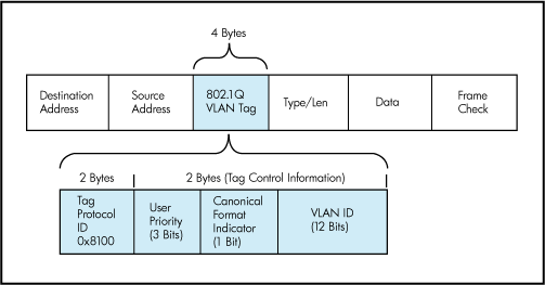
There are three different configuration modes to tag (and untag) the packets for virtual machine frames

  1. VST (VLAN range 1-4094)
  2. VGT (VLAN ID 4095 enables trunking on port group)
  3. EST (VLAN ID 0 Disables VLAN tagging on port group)

1. VST (Virtual Switch Tagging)

This is the most common configuration. In this mode, you provision one port group on a virtual switch for each VLAN, then attach the virtual machine’s virtual adapter to the port group instead of the virtual switch directly.

The virtual switch port group tags all outbound frames and removes tags for all inbound frames. It also ensures that frames on one VLAN do not leak into a different VLAN.

Use of this mode requires that the physical switch provide a trunk. E.g The ESX host network adapters must be connected to trunk ports on the physical switch.

The port groups connected to the virtual switch must have an appropriate VLAN ID specified

switchport trunk encapsulation dot1q
switchport mode trunk
switchport trunk allowed vlan x,y,z
spanning-tree portfast trunk

Note: The Native VLAN is not tagged and thus requires no VLAN ID to be set on the ESX/ESXi portgroup.

2. VGT (Virtual Guest Tagging)

You may install an 802.1Q VLAN trunking driver inside the virtual machine, and tags will be preserved between the virtual machine networking stack and external switch when frames are passed from or to virtual switches. Use of this mode requires that the physical switch provide a trunk

3. EST (External Switch Tagging)

You may use external switches for VLAN tagging. This is similar to a physical network, and VLAN configuration is normally transparent to each individual physical server.
There is no need to provide a trunk in these environments.

All VLAN tagging of packets is performed on the physical switch.

ESX host network adapters are connected to access ports on the physical switch.

The portgroups connected to the virtual switch must have their VLAN ID set to 0.

See this example snippet of a code from a Cisco switch port configuration:

switchport mode access
switchport access vlan x

Virtual Distributed Switches

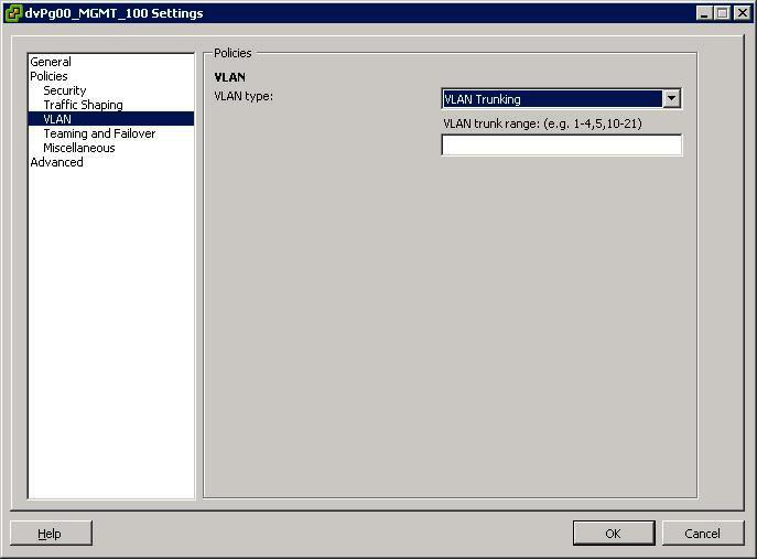
In vSphere, there’s a new networking feature which can be configured on the distributed virtual switch (or DVS). In VI3 it is only possible to add one VLAN to a specific port group in the vSwitch. in the DVS, you can add a range of VLANs to a single port group. The feature is called VLAN trunking and it can be configured when you add a new port group. There you have the option to define a VLAN type, which can be one of the following:

  • None
  • VLAN
  • VLAN trunking
  • Private VLAN. But this can only be done on the DVS, not on a regular vSwitch. See screendumps below (both from vSphere environment)
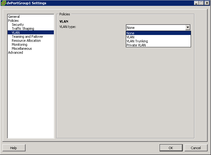
VLAN7

The VLAN policy allows virtual networks to join physical VLANs.

  • Log in to the vSphere Client and select the Networking inventory view.
  • Select the vSphere distributed switch in the inventory pane.
  • On the Ports tab, right-click the port to modify and select Edit Settings.
  • Click Policies.
  • Select the VLAN Type to use.
  • Select VLAN Trunking
  • Select a VLAN ID between 1- 4094
  • Note: Do not use VLAN ID 4095

What is a VLAN Trunk?

A VLAN trunk is a port on a physical switch that has the ability to listen and pass traffic for multiple VLANs. Trunks are used primarily to pass traffic between multiple switches.

In Cisco networks, trunking is a special function that can be assigned to a port, making that port capable of carrying traffic for any or all of the VLANs accessible by a particular switch. Such a port is called a trunk port, in contrast to an access port, which carries traffic only to and from the specific VLAN assigned to it. A trunk port marks frames with special identifying tags (either ISL tags or 802.1Q tags) as they pass between switches, so each frame can be routed to its intended VLAN. An access port does not provide such tags, because the VLAN for it is pre-assigned, and identifying markers are therefore unnecessary.

A quick note on the relationship between VLANs and vSwitch port groups. A VLAN can contain multiple port groups, but a port group can only be associated with one VLAN at any given time. A prerequisite for VLAN functionality on a vSwitch (vSS or vDS) is that the vSwitch uplinks must be connected to a trunk port on the physical switch. This trunk port will also need to include the associated VLAN ID range, enabling the physical switch to pass VLAN tags to the ESXi host. So why is any of this important? A trunk port can store and distribute multiple VLAN tags, enabling multiple traffic types to flow independently (at least logically), across the same uplink or group of uplinks in the case of teamed NICs

Use case for using VLAN trunking would be if you have multiple VLANs in place for logical separation or to isolate your VM traffic but you have a limited amount of physical uplink ports dedicated for your ESXi hosts

Networking Policies

Policies set at the standard switch or distributed port group level apply to all of the port groups on the standard switch or to ports in the distributed port group. The exceptions are the configuration options that are overridden at the standard port group or distributed port level.

  • Load Balancing and Failover Policy
  • VLAN Policy
  • Security Policy
  • Traffic Shaping Policy
  • Resource Allocation Policy
  • Monitoring Policy
  • Port Blocking Policies
  • Manage Policies for Multiple Port Groups on a vSphere Distributed Switch

Useful Post (Thanks to Mohammed Raffic)

http://www.vmwarearena.com/2012/07/vlan-tagging-vst-est-vgt-on-vmware.html?goback=.gde_42087_member_239011765

Port Group Security

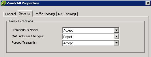
Security Options

portsecurity

Promiscuous Mode

Promiscuous mode eliminates any reception filtering that the virtual network adapter would perform so that the guest operating system receives all traffic observed on the wire. By default, the virtual network adapter cannot operate in promiscuous mode.

Although promiscuous mode can be useful for tracking network activity, it is an insecure mode of operation, because any adapter in promiscuous mode has access to the packets regardless of whether some of the packets are received only by a particular network adapter. This means that an administrator or root user within a virtual machine can potentially view traffic destined for other guest or host operating system

Note

In some situations, you might have a legitimate reason to configure a standard switch to operate in promiscuous mode (for example, if you are running network intrusion detection software or a packet sniffer

MAC Address Changes

The setting for the MAC Address Changes option affects traffic that a virtual machine receives.

When the option is set to Accept, ESXi accepts requests to change the effective MAC address to other than the initial MAC address.

When the option is set to Reject, ESXi does not honor requests to change the effective MAC address to anything other than the initial MAC address, which protects the host against MAC impersonation. The port that the virtual adapter used to send the request is disabled and the virtual adapter does not receive any more frames until it changes the effective MAC address to match the initial MAC address. The guest operating system does not detect that the MAC address change was not honored.

Note

The iSCSI initiator relies on being able to get MAC address changes from certain types of storage. If you are using ESXi iSCSI and have iSCSI storage, set the MAC Address Changes option to Accept.

In some situations, you might have a legitimate need for more than one adapter to have the same MAC address on a network—for example, if you are using Microsoft Network Load Balancing in unicast mode. When Microsoft Network Load Balancing is used in the standard multicast mode, adapters do not share MAC addresses.

MAC address changes settings affect traffic leaving a virtual machine. MAC address changes will occur if the sender is permitted to make them, even if standard switches or a receiving virtual machine does not permit MAC address chan

Forged Transmits

The setting for the Forged Transmits option affects traffic that is transmitted from a virtual machine.

When the option is set to Accept, ESXi does not compare source and effective MAC addresses.

To protect against MAC impersonation, you can set this option to Reject. If you do, the host compares the source MAC address being transmitted by the operating system with the effective MAC address for its adapter to see if they match. If the addresses do not match, ESXi drops the packet.

The guest operating system does not detect that its virtual network adapter cannot send packets by using the impersonated MAC address. The ESXi host intercepts any packets with impersonated addresses before they are delivered, and the guest operating system might assume that the packets are dropped

Note

This option is enabled by default, because it is occasionally needed to avoid software licensing problems. For example, if software on a physical machine is licensed to a specific MAC address, it will not work in a virtual machine because the VM’s MAC address is different. In this case, allowing forged transmits enables you to use the software by forging the VM’s MAC address.

However, allowing forged transmits poses a security risk.If an administrator has only authorized specific MAC addresses to enter the network, an intruder may be able to change his unauthorized MAC address to an authorized one

VDS Port Group – Port Bindings

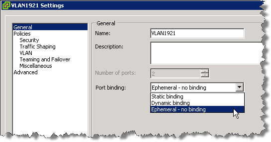
There are 3 types of Port Binding

  1. Static Binding
  2. Dynamic Binding
  3. Ephemeral Binding

Static Binding

When you connect a virtual machine to a port group configured with static binding, a port is immediately assigned and reserved for it, guaranteeing connectivity at all times. The port is disconnected only when the virtual machine is removed from the port group. You can connect a virtual machine to a static-binding port group only through vCenter Server.

Dynamic Binding

In a port group configured with dynamic binding, a port is assigned to a virtual machine only when the virtual machine is powered on and its NIC is in a connected state. The port is disconnected when the virtual machine is powered off or the virtual machine’s NIC is disconnected. Virtual machines connected to a port group configured with dynamic binding must be powered on and off through vCenter.

Dynamic binding can be used in environments where you have more virtual machines than available ports, but do not plan to have a greater number of virtual machines active than you have available ports. For example, if you have 300 virtual machines and 100 ports, but never have more than 90 virtual machines active at one time, dynamic binding would be appropriate for your port group.

Note: Dynamic binding is deprecated in ESXi 5.0.

Ephemeral Binding

In a port group configured with ephemeral binding, a port is created and assigned to a virtual machine by the host when the virtual machine is powered on and its NIC is in a connected state. The port is deleted when the virtual machine is powered off or the virtual machine’s NIC is disconnected.

You can assign a virtual machine to a distributed port group with ephemeral port binding on ESX/ESXi and vCenter, giving you the flexibility to manage virtual machine connections through the host when vCenter is down. Although only ephemeral binding allows you to modify virtual machine network connections when vCenter is down, network traffic is unaffected by vCenter failure regardless of port binding type.

Note: Ephemeral port groups should be used only for recovery purposes when you want to provision ports directly on host bypassing vCenter Server, not for any other case. This is true for several reasons:

The disadvantage is that if you configure ephemeral port binding your network will be less secure. Anybody who will gain host access can create rogue virtual machine and place it on the network or to move VMs between networks. The security hardening guide even recommends to lower the number of ports for each distributed portgroup so there are none unused.

AutoExpand (New Feature)

Note: vSphere 5.0 has introduced a new advanced option for static port binding called Auto Expand. This port group property allows a port group to expand automatically by a small predefined margin whenever the port group is about to run out of ports. In vSphere 5.1, the Auto Expand feature is enabled by default.

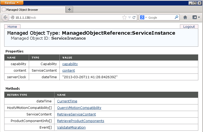
In vSphere 5.0 Auto Expand is disabled by default. To enable it, use the vSphere 5.0 SDK via the managed object browser (MOB):

  • In a browser, enter the address http://vc-ip-address/mob/.
  • When prompted, enter your vCenter Server username and password.
  • Click the Content link.

expand

  • In the left pane, search for the row with the word rootFolder.
  • Open the link in the right pane of the row. The link should be similar to group-d1 (Datacenters).
  • In the left pane, search for the row with the word childEntity. In the right pane, you see a list of datacenter links.
  • Click the datacenter link in which the vDS is defined.
  • In the left pane, search for the row with the word networkFolder and open the link in the right pane. The link should be similar to group-n123 (network).
  • In the left pane, search for the row with the word childEntity. You see a list of vDS and distributed port group links in the right pane.
  • Click the distributed port group for which you want to change this property.
  • In the left pane, search for the row with the word config and click the link in the right pane.
  • In the left pane, search for the row with the word autoExpand. It is usually the first row.
  • Note the corresponding value displayed in the right pane. The value should be false by default.
  • In the left pane, search for the row with the word configVersion. The value should be 1 if it has not been modified.
  • Note the corresponding value displayed in the right pane as it is needed later.
  • Note: I found mine said AutoExpand=true and ConfigVersion=3

expand2

  • Go back to the distributed port group page.
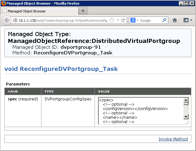
  • Click the link at the bottom of the page that reads ReconfigureDv<PortGroup>_Task
  • A new window appears.

expand3

  • In the Value field, find the following lines and adjust them to the values you recorded earlier

<spec>
<configVersion>3</configVersion>

  • And scroll to the end and find and adjust this

<autoExpand>true</autoExpand>
</spec>

  • where configVersion is what you recorded in step 15.
  • Click the Invoke Method link.
  • Close the window.
  • Repeat Steps 10 through 14 to verify the new value for autoExpand.

Useful VMware Article

http://kb.vmware.com/selfservice/microsites/search.do?language=en_US&cmd=displayKC&externalId=1022312

Useful Blog on why to use Static Port Binding on vDS Switches

http://blogs.vmware.com/vsphere/2012/05/why-use-static-port-binding-on-vds-.html