Archive for VMware

Choosing a network adapter for your virtual machine

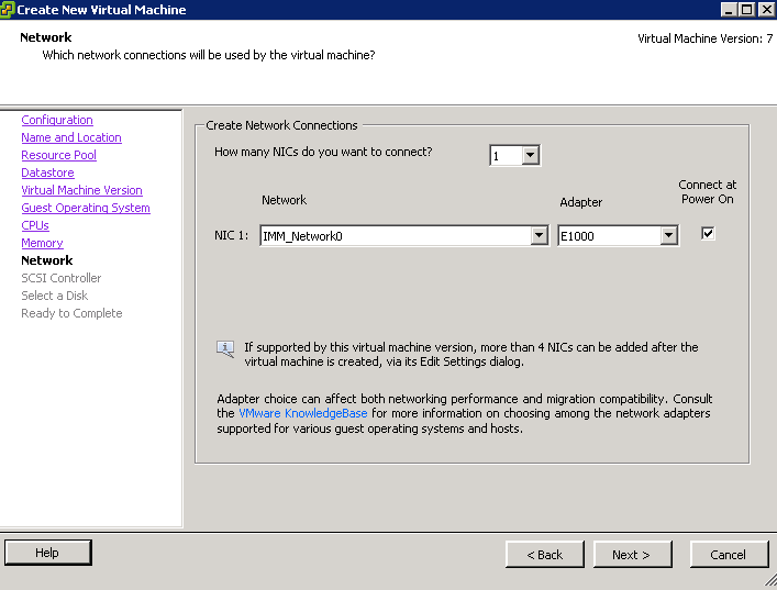
When creating a Virtual machine, VMware will normally offer you several choices of network adaptor depending on what O/S you select.

Network Adaptor Types

  • Vlance – An emulated version of the AMD 79C970 PCnet32- LANCE NIC, an older 10Mbps NIC with drivers available in most 32-bit guest operating systems except Windows Vista and later. A virtual machine configured with this network adapter can use its network immediately.
  • VMXNET – The VMXNET virtual network adapter has no physical counterpart. VMXNET is optimized for performance in a virtual machine. Because operating system vendors do not provide built-in drivers for this card, you must install VMware Tools to have a driver for the VMXNET network adapter available.
  • Flexible – The Flexible network adapter identifies itself as a Vlance adapter when a virtual machine boots, but initializes itself and functions as either a Vlance or a VMXNET adapter, depending on which driver initializes it. With VMware Tools installed, the VMXNET driver changes the Vlance adapter to the higher performance VMXNET adapter.
  • E1000— An emulated version of the Intel 82545EM Gigabit Ethernet NIC. A driver for this NIC is not included with all guest operating systems. Typically Linux versions 2.4.19 and later, Windows XP Professional x64 Edition and later, and Windows Server 2003 (32-bit) and later include the E1000 driver.Note: E1000 does not support jumbo frames prior to ESX/ESXi 4.1.
  • E1000e – This feature would emulate a newer model of Intel gigabit NIC (number 82574) in the virtual hardware. This would be known as the “e1000e” vNIC. e1000e would be available only on hardware version 8 (and newer) VMs in vSphere5. It would be the default vNIC for Windows 8 and newer (Windows) guest OSes. For Linux guests, e1000e would not be available from the UI (e1000, flexible vmxnet, enhanced vmxnet, and vmxnet3 would be available for Linux).
  • VMXNET 2 (Enhanced) – The VMXNET 2 adapter is based on the VMXNET adapter but provides some high-performance features commonly used on modern networks, such as jumbo frames and hardware offloads. This virtual network adapter is available only for some guest operating systems on ESX/ESXi 3.5 and late
  • VMXNET 3– The VMXNET 3 adapter is the next generation of a paravirtualized NIC designed for performance, and is not related to VMXNET or VMXNET 2. It offers all the features available in VMXNET 2, and adds several new features like multiqueue support (also known as Receive Side Scaling in Windows), IPv6 offloads, and MSI/MSI-X interrupt delivery.VMXNET 3 is supported only for virtual machines version 7 and later, with a limited set of guest operating systems:
  • 32- and 64-bit versions of Microsoft Windows XP,7, 2003, 2003 R2, 2008, and 2008 R2
  • 32- and 64-bit versions of Red Hat Enterprise Linux 5.0 and later
  • 32- and 64-bit versions of SUSE Linux Enterprise Server 10 and later
  • 32- and 64-bit versions of Asianux 3 and later
  • 32- and 64-bit versions of Debian 4
  • 32- and 64-bit versions of Ubuntu 7.04 and later
  • 32- and 64-bit versions of Sun Solaris 10 U4 and later

New Features

  • TSO, Jumbo Frames, TCP/IP Checksum Offload

You can enable Jumbo frames on a vSphere Distributed Switch or Standard switch by changing the maximum MTU. TSO (TCP Segmentation Offload is enabled on the VMKernel interface by default but must be enabled at the VM level. Just change the nic to VMXNet 3 to take advantage of this feature

  • MSI/MSI‐X support (subject to guest operating system
    kernel support)

A Message Signaled Interrupt is a write from the device to a special address which causes an interrupt to be received by the CPU. The MSI capability was first specified in PCI 2.2 and was later enhanced in PCI 3.0 to allow each interrupt to be masked individually. The MSI-X capability was also introduced with PCI 3.0.  It supports more interrupts – 26 per device than MSI and allows interrupts to be independently configured.

MSI, Message Signaled Interrupts, uses in-band pci memory space message to raise interrupt, instead of conventional out-band pci INTx pin. MSI-X is an extension to MSI, for supporting more vectors. MSI can support at most 32 vectors while MSI-X can support up to 2048. Using msi can lower interrupt latency, by giving every kind of interrupt its own vector/handler. When kernel see the message, it will directly vector to the interrupt service routine associated with the address/data. The address/data (vector) were allocated by system, while driver needs to register handler with the vector. 

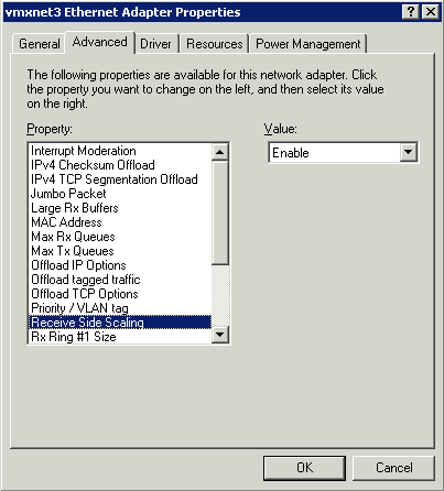
  • Receive Side Scaling (RSS, supported in Windows 2008 when explicitly enabled)

When Receive Side Scaling (RSS) is enabled, all of the receive data processing for a particular TCP connection is shared across multiple processors or processor cores. Without RSS all of the processing is performed by a single processor, resulting in inefficient system cache utilization

RSS is enabled on the Advanced tab of the adapter property sheet. If your adapter does not support RSS, or if your operating system does not support it, the RSS setting will not be displayed.

rss

  • IPv6 TCP Segmentation Offloading (TSO over IPv6)

IPv6 TCP Segmentation Offloading significantly helps to reduce transmit processing performed by the vCPUs and improves both transmit efficiency and throughput. If the uplink NIC supports TSO6, the segmentation work will be offloaded to the network hardware; otherwise, software segmentation will be conducted inside the VMkernel before passing packets to the uplink. Therefore, TSO6 can be enabled for VMXNET3 whether or not the hardware NIC supports it

  • NAPI (supported in Linux)

The VMXNET3 driver is NAPI‐compliant on Linux guests. NAPI is an interrupt mitigation mechanism that improves high‐speed networking performance on Linux by switching back and forth between interrupt mode and polling mode during packet receive. It is a proven technique to improve CPU efficiency and allows the guest to process higher packet loads

New API (also referred to as NAPI) is an interface to use interrupt mitigation techniques for networking devices in the Linux kernel. Such an approach is intended to reduce the overhead of packet receiving. The idea is to defer incoming message handling until there is a sufficient amount of them so that it is worth handling them all at once.

A straightforward method of implementing a network driver is to interrupt the kernel by issuing an interrupt request (IRQ) for each and every incoming packet. However, servicing IRQs is costly in terms of processor resources and time. Therefore the straightforward implementation can be very inefficient in high-speed networks, constantly interrupting the kernel with the thousands of packets per second. Overall performance of the system as well as network throughput can suffer as a result.

Polling is an alternative to interrupt-based processing. The kernel can periodically check for the arrival of incoming network packets without being interrupted, which eliminates the overhead of interrupt processing. Establishing an optimal polling frequency is important, however. Too frequent polling wastes CPU resources by repeatedly checking for incoming packets that have not yet arrived. On the other hand, polling too infrequently introduces latency by reducing system reactivity to incoming packets, and it may result in the loss of packets if the incoming packet buffer fills up before being processed.

As a compromise, the Linux kernel uses the interrupt-driven mode by default and only switches to polling mode when the flow of incoming packets exceeds a certain threshold, known as the “weight” of the network interface

  • LRO (supported in Linux, VM‐VM only)

VMXNET3 also supports Large Receive Offload (LRO) on Linux guests. However, in ESX 4.0 the VMkernel backend supports large receive packets only if the packets originate from another virtual machine running on the same host.
VMware Resource Pools

What is a Resource Pool?

A Resource Pool provides a way to divide the resources of a standalone host or a cluster into smaller pools. A Resource Pool is configured with a set of CPU and Memory resources that the virtual machines that run in the Resource Pool share. Resource Pools are self-contained and isolated from other Resource Pools.

Using Resource Pools

After you create a Resource Pool, the vCenter Server manages the shared resource and allocates them to VMs within the Resource Pool. Using these you can

  • Allocate processor and memory resources to virtual machines running on the same host or cluster
  • Establish minimum, maxmimum and proportional resource shares for CPU and memory
  • Modify allocations while virtual machines are running
  • Enable applications to dynamically acquire more resources to accomodate peak performance.
  • Access control and delegation—When a top-level administrator makes a resource pool available to a department-level administrator, that administrator can then perform all virtual machine creation and management within the boundaries of the resources to which the resource pool is entitled by the current
    shares, reservation, and limit settings. Delegation is usually done in conjunction with permissions settings.

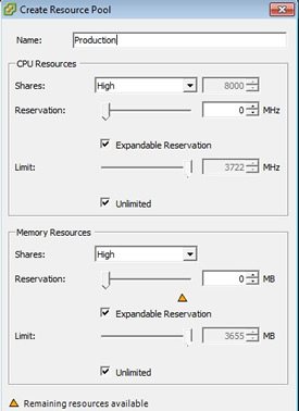
For each resource pool, you specify reservation, limit, shares, and whether the reservation should be expandable

Resource Pool Creation Example

This procedure example demonstrates how you can create a resource pool with the ESX/ESXi host as the parent resource.
Assume that you have an ESX/ESXi host that provides 6GHz of CPU and 3GB of memory that must be shared between your marketing and QA departments. You also want to share the resources unevenly, giving one department (QA) a higher priority. This can be accomplished by creating a resource pool for each department and using the Shares attribute to prioritize the allocation of resources.
The example procedure demonstrates how to create a resource pool, with the ESX/ESXi host as the parent resource.

Procedure

  1. In the Create Resource Pool dialog box, type a name for the QA department’s resource pool (for example,RP-QA).
  2. Specify Shares of High for the CPU and memory resources of RP-QA.
  3. Create a second resource pool, RP-Marketing. Leave Shares at Normal for CPU and memory.
  4. Click OK to exit.

If there is resource contention, RP-QA receives 4GHz and 2GB of memory, and RP-Marketing 2GHz and 1GB.

Otherwise, they can receive more than this allotment. Those resources are then available to the virtual machines in the respective resource pools.

Resource Pool Shares

If you have 3 Resource Pools which are Low, Normal and High, then VMware will allocate the following shares/ratio of total resources

  • High=8000
  • Medium=4000
  • Low=2000

If you have 2 Resource Pools which are Normal and High, then VMware will allocate the following shares/ratio of total resources

  • 6600
  • 3300

Note: The share values would only kick in when the host was having resource contention issues

Can you over-commit memory within resource pools?

The resource pools are expandable and you can over commit them but you will run into performance issues so its not advised to do this so its better to have enough memory assigned to them.

Interesting Point- May need further clarification

It has been suggested that a High, Medium, Low model was best and in general I lean towards this model, however there is one, often overlooked problem with this method. To illustrate with an example if you have a Resource Pool with 2000 shares and contains 4 VM’s then 2000/4 = 500 shares per VM. Imagine you have a High Resource Pool with 8000 shares and 10 VM’s then 8000/16 = 500 shares per VM. This indicates that all the virtual machines would actually receive the same amount of resource shares in the cluster. Take that one step further and increase the number of VM’s to 20, then 8000/20 = 400 in fact less shares that those in the Low Resource Pool.

Duncan Epping describes the above really well in the below article

http://www.yellow-bricks.com/2010/02/22/the-resource-pool-priority-pie-paradox/

and further information

Resource Pools have become a hot topic due to the vSphere 4 Design class.  This class apparently was codesigned with some VCDXs.  It became clear during the design that even VCDXs had misconceptions about how RPs actually worked.  This misconception has actually led to the coursework explicitly calling out RPs as something to be careful of,  or even just flat our avoid.  The rec is to use shares on VMs. If you have High (8000), Normal (4000), and Low (2000) RPs for the purpose of controlling shares and they each have 4 VMs in them,  then the RPs will work the way most of us thought they would work.  However,  if you move 4 of the VMs to the High then you have 8H, 2N, and 2L.  When there is contention the shares will look like this: H – 8000 shares / 8 VMs = 1000 shares per VM N – 4000 shares / 2 VMs = 2000 shares per VM L – 2000 shares / 2 VMs = 1000 shares per VM In this scenario your High RP VMs are acutally getting less then the Normal VMs and equal to the L VMs.   So basically the only way for the RPs to work the way that WE want them to is to maintain a balanced # of VMs per RP or if they are unbalanced make sure that the lower tiered RPs contain more VMs than the higher tiers. Remmember shares only come into play during times of resource contention.  So if you have no contention then the RPs are used for anything but organization.

VMware Snapshots Explained

A VMware snapshot is a copy of Virtual Machine Disk file (VMDK) at a particular moment in time. By taking multiple snapshots, you can have several restore points for a virtual machine (VM). While more VMware snapshots will improve the resiliency of your infrastructure, you must balance those needs against the storage space they consume.

The size of a snapshot file can never exceed the size of the original disk file. Any time a disk block is changed, the snapshot is created in the delta file and simply updated as changes are made. If you changed every single disk block on your server after taking a snapshot, your snapshot would still be the same size as your original disk file. But there’s some additional overhead disk space that contains information used to manage the snapshots. The maximum overhead disk space varies and it’s based on the Virtual Machine Files System block size

Block Size Maximum VMDK Size Max Overhead
1MB 256GB 2GB
2MB 512GB 4GB
4MB 1024GB 8GB
8MB 2048GB 16GB

The overhead disk space that’s required can cause the creation of snapshots to fail if a VM’s virtual disk is close the maximum VMDK size for a VMFS volume. If a VM’s virtual disk is 512 GB on a VMFS volume with a 2 MB block size, for example, the maximum snapshot size would be 516 GB (512 GB + 4 GB), which would exceed the 512 GB maximum VMDK size for the VMFS volume and cause the snapshot creation to fail

Snapshots grow in 16 MB increments to help reduce SCSI reservation conflicts. When requests are made to change a block on the original disk, it is instead changed in the delta file. If the previously changed disk block in a delta file is changed again it will not increase the size of the delta file because it simply updates the existing block in the delta file.

The rate of growth of a snapshot will be determined by how much disk write activity occurs on your server. Servers that have disk write intensive applications, such as SQL and Exchange, will have their snapshot files grow rapidly. On the other hand, servers with mostly static content and fewer disk writes, such as Web and application servers, will grow at a much slower rate. When you create multiple snapshots, new delta files are created and the previous delta files become read-only. With multiple snapshots each delta file can potentially grow as large as the original disk file

Different Types of snapshot files

*–delta.vmdk file: This is the differential file created when you take a snapshot of a VM. It is also known as the redo-log file. The delta file is a bitmap of the changes to the base VMDK, thus it can never grow larger than the base VMDK (except for snapshot overhead space). A delta file will be created for each snapshot that you create for a VM. An extra delta helper file will also be created to hold any disk changes when a snapshot is being deleted or reverted. These files are automatically deleted when the snapshot is deleted or reverted in snapshot manager.

*.vmsd file: This file is used to store metadata and information about snapshots. This file is in text format and will contain information such as the snapshot display name, unique identifier (UID), disk file name, etc. It is initially a 0 byte file until you create your first snapshot of a VM. From that point it will populate the file and continue to update it whenever new snapshots are taken.

This file does not cleanup completely after the snapshots are taken. Once you delete a snapshot, it will still increment the snapshot’s last unique identifier for the next snapshot.

*.vmsn file: This is the snapshot state file, which stores the exact running state of a virtual machine at the time you take that snapshot. This file will either be small or large depending on if you select to preserve the VM’s memory as part of the snapshot. If you do choose to preserve the VM’s memory, then this file will be a few megabytes larger than the maximum RAM memory allocated to the VM.

This file is similar to the VMware suspended state (.vmss) file. A .vmsn file will be created for each snapshot taken on the VM; these files are automatically deleted when the snapshot is removed

Deleting or reverting to snapshots

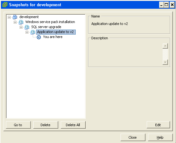
When you delete all snapshots for a VM, all of the delta files that are created are merged back into the original VMDK disk file for the VM and then deleted. If you choose to delete only an individual snapshot, then just that snapshot is merged into its parent snapshot. If you choose to revert to a snapshot, the current disk and memory states are discarded and the VM is brought back to the reverted-to state. Whichever snapshot you revert to then becomes the new parent snapshot. The parent snapshot, however, is not always the most recently taken snapshot. If you revert back to an older snapshot, it then becomes the parent of the current state of the virtual machine. The parent snapshot is always noted by the “You are here” label under it in the Snapshot Manager.

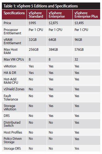
vSphere 5.0 Versions and Features

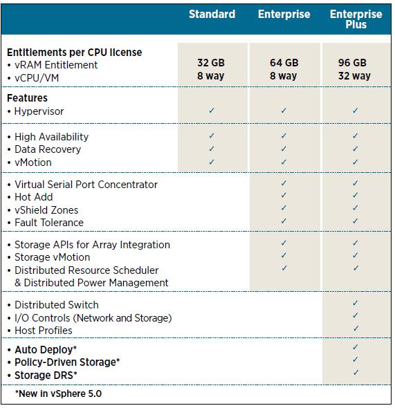
Just a quick post for reference to features and functionality gained from each version of vSphere 5

Changing vCenters IP Address

The Challenge

Currently at my work, our network team have decided they want to create a new VMware Management VLAN (Headache Time) They want us to move vCenter on to this new VLAN and assign a new…

  1. IP Address
  2. Subnet Mask
  3. Gateway
  4. VMware Port Group VLAN ID

So what can possibly go wrong?…. Apparently quite a lot

Once the networking is changed on your vCenter, the ESX(i) hosts disconnect because they store the IP address of the vCenter Server in configuration files on each of the individual servers. This incorrect address continues to be used for heartbeat packets to vCenter Server.

You may also experience connectivity issues with vSphere Update Manager, Autodeploy, Syslog and Dump Collector.

Things to remember

  1. Ensure you have a vCenter database backup.
  2. Once the vCenter IP address has changed all that should be necessary is to reconnect the hosts back into vCenter.
  3. Please ensure that the vCenter DNS entry gets updated with the correct IP address. In addition ensure you have intervlan routing configured correctly.
  4. In the worst case scenario and you have to recreate the vCenter database then all you will lose is historic performance data and resource pools.
  5. You will need to change the Port Group VLAN
  6. Creating a second nic on the vCenter and assigning it the IP address of the new VLAN won’t be of assistance as you will need to select a managed vCenter IP address if you do this

How to resolve this

There are two methods to get the ESX hosts connected again. Try each one in order

Method 1
  1. Log in as root to the ESX host with an SSH client.
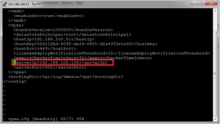
  2. Using a text editor, edit the /etc/opt/vmware/vpxa/vpxa.cfg file and change the parameter to the new IP of the vCenter Server.
  3. Or for ESXi 4 and 5, navigate to the folder /etc/vmware/vpxa and with vi open the file: vpxa.cfg. Search for the line that starts with: and then change this parameter to the new IP address of the vCenter Server.
  4. Save your changes and exit.
  5. Restart the management agents on the ESX.
  6. Restart the VirtualCenter Server service with this command: # services.sh
  7. Return to the vCenter Server and restart the “VMware VirtualCenter Server” Service.

Note: This procedure can be performed on an ESXi host through Tech Support mode with the help of a VMware Technical Support Engineer.

Method 2
  1. From vSphere Client, right-click the ESX host and click Disconnect.
  2. From vSphere Client, right-click the ESX host and click Reconnect. If the IP is still not correct, go to step 3.
  3. From vSphere Client, right-click the ESX host and click Remove.
  4. Caution: After removing the host from vCenter Server, all the performance data for the virtual machines and the performance data for the host will be lost
  5. Reinstall the VMware vCenter Server agent.
  6. Select New > Add Host.
  7. Enter the information used for connecting to the host

Firewall/Router Passthrough

If the IP traffic between the vCenter Server and ESX host is passing through a NAT device like a firewall or router and the vCenter Server’s IP is translated to an external or WAN IP, update the Managed IP address:
  1. From vSphere Client connected to the vCenter Server top menu, click Administration and choose VirtualCenter Management Server Configuration.
  2. Click Runtime Settings from the left panel.
  3. Change the vCenter Server Managed IP address.
  4. If the DNS name of the vCenter Server has changed, update the vCenter Server Name field with the new DNS name

How we changed IP Address step by step on vSphere 4.1

  • First of all Remote Desktop into your vCenter Server and change the IP Address, Subnet Mask and Gateway.
  • Make sure inter vlan routing is configured between your new subnet and the subnet your DNS servers are on if this is the case
  • Go to your DNS Server and delete the entry for your current vcenter server
  • Add the new A Record for your vCenter Server
  • You may need to run an ipconfig /flushdns on the systems you are working on.
  • Try reconnecting via Remote Desktop to your vCenter Server to establish connectivity
  • Click Home and go to vCenter Server Settings and adjust vCenter’s IP address
  • At this point, all your hosts will have disconnected? (Don’t panic!)
  • At this point we logged into the host which runs vCenter using the vClient and changed the VLAN on the port group vCenter was on.
  • Go back to your logon into vCenter
  • Right click on the first disconnected hosts and click Connect
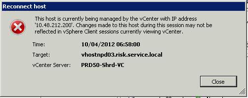
  • The below error message will appear

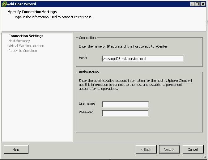
  • Click Close and then an Add host box will appear as per below screenprint

  • The host should now connect back in and adjust for HA

If you get any error messages afterwards then the IP Addres will need to be updated in a couple of other places. See link below

http://kb.vmware.com/selfservice/microsites/search.do?language=en_US&cmd=displayKC&externalId=1014213


VMware “Host Mem MB” and “Guest Mem MB”

If you click on the cluster, then the virtual machines tab or on any virtual machine you will see a row of tabs with details on about performance. The below 3 give very accurate memory statistics which can help with future planning or even seeing where a performance problem lies

Memory Size -MB

The amount of memory given by an admin to the machine initially on build

Host Mem – MB

The metrics here is showing you how much memory a particular VM is consuming from the ESX(i) host that it’s being hosted on

Guest Mem – %

This is just a metric to show you how much of that memory is actually being actively used from the overall allocated memory.

VMware Memory Resource Management Doc

Understanding Memory Resource Management in VMware® ESX™ Server

Further explanation

What tends to confuse people is a rather high consumed host memory versus a low active guest memory … usually followed by the question on how exactly active guest memory is calculated.

1) Why is consumed host memory usage higher than active guest memory? (p.5)

“The hypervisor knows when to allocate host physical memory for a virtual machine because the first memory access from the virtual machine to a host physical memory will cause a page fault that can be easily captured by the hypervisor. However, it is difficult for the hypervisor to know when to free host physical memory upon virtual machine memory deallocation because the guest operating system free list is generally not publicly accessible. Hence, the hypervisor cannot easily find out the location of the free list and monitor its changes.”

So the host allocates memory pages upon their first request from the guest (that’s why consumed is less than the configured maximum), but doesn’t deallocate them once they are freed in the guest OS (because the host simply doesn’t see those guest deallocations). If the guest OS re-uses such previously allocated pages, the host won’t allocate more host memory. If the guest OS however allocates different pages, the host will also allocate more memory (up to the point where all configured memory pages for the specific guest have been allocated).

2) How is active guest memory calculated? (p.12)

“At the beginning of each sampling period, the hypervisor intentionally invalidates several randomly selected guest physical pages and starts to monitor the guest accesses to them. At the end of the sampling period, the fraction of actively used memory can be estimated as the fraction of the invalidated pages that are re-accessed by the guest during the epoch”.

DRS

What is DRS?

A DRS cluster is a collection of ESXi hosts and associated virtual machines with shared resources and a shared interface. Before you can obtain the benefits of cluster-level resource management you must create a DRS cluster.
When you add a host to a DRS cluster, the host’s resources become part of the cluster’s resources. In addition to this aggregation of resources, with a DRS cluster you can support cluster-wide resource pools and enforce cluster-level resource allocation policies. The following cluster-level resource management capabilities are also available.

DRS must use Shared Storage and a vMotion network

  • Load Balancing

The distribution and usage of CPU and memory resources for all hosts and virtual machines in the cluster are continuously monitored. DRS compares these metrics to an ideal resource utilization given the attributes of the cluster’s resource pools and virtual machines, the current demand, and the imbalance target. It then performs (or recommends) virtual machine migrations accordingly. When you first power on a virtual machine in the cluster, DRS attempts to maintain proper load balancing by either placing the virtual machine on an appropriate host or making a recommendation.

  • Power management

When the vSphere Distributed Power Management (DPM) feature is enabled, DRS compares cluster- and host-level capacity to the demands of the cluster’s virtual machines, including recent historical demand. It places (or recommends placing) hosts in standby power mode if sufficient excess capacity is found or powering on hosts if capacity is needed. Depending on the resulting host power state recommendations, virtual machines might need to be migrated to and from the hosts as well.

  • Affinity Rules

You can control the placement of virtual machines on hosts within a cluster, by
assigning affinity rules.

DRS, EVC and FT

Depending on whether or not Enhanced vMotion Compatibility (EVC) is enabled, DRS behaves differently when you use vSphere Fault Tolerance (vSphere FT) virtual machines in your cluster.

DRS

Migration Recommendations

The system supplies as many recommendations as necessary to enforce rules and balance the resources of the cluster. Each recommendation includes the virtual machine to be moved, current (source) host and destination host, and a reason for the recommendation. The reason can be one of the following:

  • Balance average CPU loads or reservations
  • Balance average memory loads or reservations
  • Satisfy resource pool reservations
  • Satisfy an affinity rule.
  • Host is entering maintenance mode or standby mode.

Note: If you are using the vSphere Distributed Power Management (DPM) feature, in addition to migration recommendations, DRS provides host power state recommendations

Using DRS Affinity Rules

You can control the placement of virtual machines on hosts within a cluster by using affinity rules. You can create two types of rules.

  • VM-Host

Used to specify affinity or anti-affinity between a group of virtual machines and a group of hosts. An affinity rule specifies that the members of a selected virtual machine DRS group can or must run on the members of a specific host DRS group. An anti-affinity rule specifies that the members of a selected virtual machine DRS group cannot run on the members of a specific host DRS group.

  • VM-VM

Used to specify affinity or anti-affinity between individual virtual machines. A rule specifying affinity causes DRS to try to keep the specified virtual machines together on the same host, for example, for performance reasons. With an anti-affinity rule, DRS tries to keep the specified virtual machines apart, for example, so that when a problem occurs with one host, you do not lose both virtual machines. When you add or edit an affinity rule, and the cluster’s current state is in violation of the rule, the system continues to operate and tries to correct the violation. For manual and partially automated DRS clusters, migration recommendations based on rule fulfillment and load balancing are presented for approval. You are not required to fulfill the rules, but the corresponding recommendations remain until the rules are fulfilled.

To check whether any enabled affinity rules are being violated and cannot be corrected by DRS, select the cluster’s DRS tab and click Faults. Any rule currently being violated has a corresponding fault on this page.
Read the fault to determine why DRS is not able to satisfy the particular rule. Rules violations also produce a log event.

DRS Automation Levels

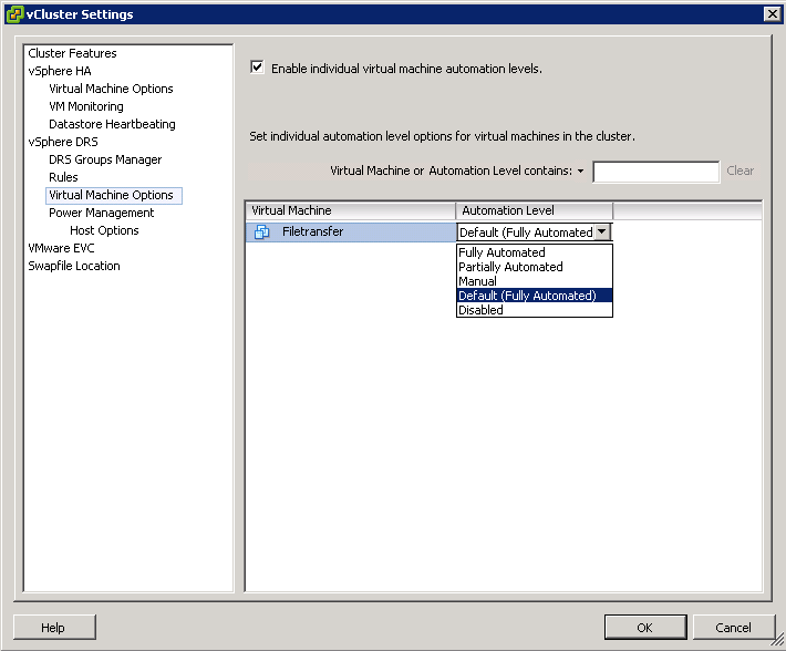
Someone at my work asked me about these levels and wanted an explanation for the Aggressive Level. He said he envisaged machines continually moving around in a state of perpetual motion. Lets find out!

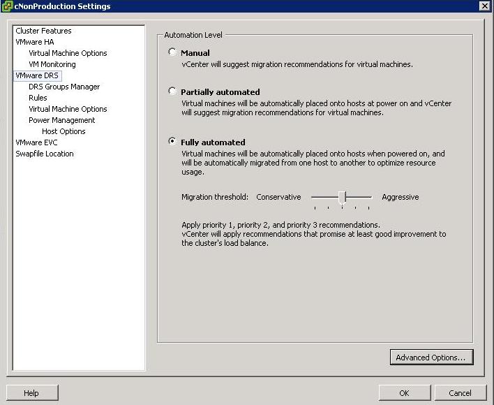
Just as a note, you access DRS Automation Level Settings by right clicking on the cluster and selecting Edit Settings, then selecting VMware DRS

There are 3 settings

  1. Manual – vCenter will suggest migration recommendations for virtual machines
  2. Partially Automated – Virtual machines will be placed onto hosts at power on and vCenter will suggest migration recommendations for virtual machines
  3. Fully Automated – Virtual machines will be automatically places on to hosts when powered on and will be automatically migrated from one host to another to optimize resource usage

For Fully Automated there is a slider called Migration threshold

You can move the slider to use one of the five levels

  • Level 1 – Apply only five-star recommendations. Includes recommendations that must be followed to satisfy cluster constraints, such as affinity rules and host maintenance. This level indicates a mandatory move, required to satisfy an affinity rule or evacuate a host that is entering maintenance mode.
  • Level 2 – Apply recommendations with four or more stars. Includes Level 1 plus recommendations that promise a significant improvement in the cluster’s load balance.
  • Level 3 – Apply recommendations with three or more stars. Includes Level 1 and 2 plus recommendations that promise a good improvement in the cluster’s load balance.
  • Level 4 – Apply recommendations with two or more stars. Includes Level 1-3 plus recommendations that promise a moderate improvement in the cluster’s load balance.
  • Level 5 – Apply all recommendations. Includes Level 1-4 plus recommendations that promise a slight improvement in the cluster’s load balance.

Some interesting facts

  • DRS has a threshold of up to 60 vMotion events per hour
  • It will check for imbalances in the cluster once every five minutes

vCenter Console

DRS

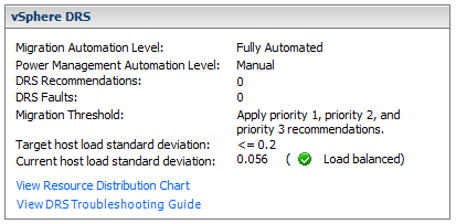
When the Current host load standard deviation exceeds the target host load standard deviation, DRS will make recommendations and take action based on the automation level and migration threshold

The target host load standard deviation is derived from the migration threshold setting. A load is considered imbalanced as long as the current value exceeds the migration threshold.

Each host has a host load metric based upon the CPU and memory resources in use. It is described as the sum of expected virtual machine loads divided by the capacity of the host. The LoadImbalanceMetric also known as the current host load standard deviation is the standard deviation (average of averages) of all host load metrics in a cluster.

DRS decides what virtual machines are migrated based on simulating a move and recalculating the current host load standard deviation and making a recommendation. As part of this simulation, a cost benefit and risk analysis is performed to determine best placement. DRS will continue to perform simulations and will make recommendations as long as the current host load exceeds the target host load.

Properly size virtual machine automation levels based on Application Requirements

  • When a virtual machine is powered on, DRS is responsible for performing initial placement. During initial placement, DRS considers the “worst case scenario” for a VM. For example, when a new server that has been overspec’d gets powered on, DRS will actively attempt to identify a host that can guarantee that CPU and RAM to the VM. This is due to the fact that historical resource utilization statistics for the VM are unavailable. If DRS cannot find a cluster host able to accommodate the VM, it will be forced to “defragment” the cluster by moving other VMs around to account for the one being powered on. As such, VMs should be be sized based on their current workload.
  • When performing an assessment of a physical environment as part of a vSphere migration, an administrator should leverage the resource utilization data from VMware Capacity Planner in allocating resources to VMs.
  • Do not set VM reservations too high as this can affect DRS Balancing DRS might not have excess resources to move VMs around
  • Group Virtual Machines for a multi-tier service into a Resource Pool
  • Don’t forget to calculate memory overhead when sizing VMs into clusters
  • Use Resource Settings such as Shares, Limits and Reservations only when necessary

Automation

  • You might want to keep VMs on the same host if they are part of a tiered application that runs on multiple VMs, such as a web, application, or database server.
  • You might want to keep VMs on different hosts for servers that are clustered or redundant, such as Active Directory (AD), DNS, or web servers, so that a single ESX failure does not affect both servers at the same time. Doing this ensures that at least one will stay up and remain available while the other recovers from a host failure.
  • You might want to separate servers that have high I/O workloads so that you do not overburden a specific host with too many high-workload servers.
  • Keep servers like vCenter, the vCenter DB and Domain Controllers as a high priority

What machines can you “not” Storage vMotion

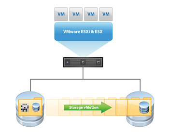
VMware Storage VMotion is a component of VMware vSphere™that provides an intuitive interface for live migration of virtual machine disk files within and across storage arrays with no downtime or disruption in service. Storage VMotion relocates virtual machine disk files from one shared storage location to another shared storage location with zero downtime, continuous service availability and complete transaction integrity. StorageVMotion enables organizations to perform proactive storage migrations, simplify array migrations, improve virtual machine storage performance and free up valuable storage capacity.Storage VMotion is fully integrated with VMware vCenter Server to provide easy migration and monitoring.

How does it work

1. Before moving a virtual machines disk file, Storage VMotion moves the “home directory” of the virtual machine to the new location. The home directory contains meta data about the virtual machine (configuration, swap and log files).

2. After relocating the home directory, Storage VMotion copies the contents of the entire virtual machine storage disk file to the destination storage host, leveraging “changed block tracking” to maintain data integrity during the migration process.

3. Next, the software queries the changed block tracking module to determine what regions of the disk were written to during the first iteration, and then performs a second iteration of copy, where those regions that were changed during the first iteration copy (there can be several more iterations).

4. Once the process is complete, the virtual machine is quickly suspended and resumed so that it can begin using the virtual machine home directory and disk file on the destination datastore location.

5. Before VMware ESX allows the virtual machine to start running again, the final changed regions of the source disk are copied over to the destination and the source home and disks are removed.

What machines can you not Storage vMotion?

1. Virtual machines with snapshots cannot be migrated using Storage vMotion

2. Migration of virtual machines during VMware Tools installation is not supported

3. The host on which the virtual machine is running must have a license that includes Storage vMotion.

4. ESX/ESXi 3.5 hosts must be licensed and configured for vMotion. ESX/ESXi 4.0 and later hosts do not require vMotion configuration in order to perform migration with Storage vMotion.

5. The host on which the virtual machine is running must have access to both the source and target datastores

6. Virtual machine disks in non-persistent mode cannot be migrated

7. Clustered applications or clustered virtual machine configurations do not support Storage vMotion.

8. For vSphere 4.0 and higher, Virtual Disks and Virtual RDM pointer files can be relocated to a destination datastore, and can be converted to thick provisioned or thin provisioned disks during migration as long as the detsination is not an NFS Datastore

9. Physical Mode Pointer files can be relocated to the destination datastore but cannot be converted

vSphere 5 Licensing

This post has been written so I and others can start to understand vSphere licensing

Comparison of vSphere 5 Editions

VMware vSphere 5 licensing

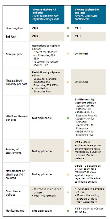
vSphere 5 will be licensed on a per processor basis with a vRAM entitlement. Each vSphere 5 processor license will entitle the purchaser to a specific amount of vRAM, or memory configured to virtual machines. The vRAM entitlement can be pooled across a vSphere environment to enable a true cloud or utility-based IT consumption model. Just like VMware technology offers customers an evolutionary path from the traditional datacenter to a cloud infrastructure, the new vSphere 5 licensing model allows customers to evolve to a cloud-like “pay for consumption” model without disrupting established purchase, deployment, and license management practices and processes. Unlike vSphere 4.x licenses, vSphere 4.x licenses, vSphere 5 licenses do not impose any limits on the number of cores per processors and maximum size of RAM capacity per host

Licensing PDF

http://www.vmware.com/files/pdf/vsphere_pricing.pdf

A diagram showing licesning changes between vSphere 4.x and vSphere 5.x

Should vCenter and the vCenter DB be on the same subnet as the hosts

Because vSphere is not a single stand-alone server, application, or isolated computing system, the pieces of the puzzle will require some form of communication between them. There are many possible configuration scenarios depending on the environment in which vSphere is being deployed.

A vCenter Server must be able to communicate with each host and each vSphere client. Furthermore, if a remote database server is utilized rather than a local instance of the database, the required TCP/IP ports for that database installation are also required.

If an instance of vCenter Server is installed on Windows Server 2008, you must either disable the Windows Firewall or make an exception to allow communication between all of the required pieces of the environment.

vCenter Server requires several ports to be open when you select a default installation. Each of these ports will be used for a different portion of the overall communications path. To enable proper communication between each of the components, consult a network engineer to ensure the appropriate ports are open for communication.

Web ports that are required to be open include the following:

Port


Description

80

Required for the purpose of redirecting nonsecure requests to vCenter Server on a secure port

443

The default port used to communicate with vSphere Client and to look for data from vSphere Web Access Client and other VMware Software Development Kit (SDK) applications such as the VI Toolkit. You can change this port, but vSphere Client and any SDK applications must use the vCenter Server name, followed by the nondefault port number

8080

The port used by Web Services HTTP.

8443

The port used by Web Services HTTPS

389

The standard port number used for Lightweight Directory Access Protocol (LDAP) services. This port is used for the Directory Services component of vCenter Server. It must be available to vCenter Server, even if vCenter Server is not part of a Linked Mode Group. You can change from port 389 to any available port ranging from 1025 to 65535. This is the normal LDAP port that the vCenter Server Active Directory Application Mode (ADAM) instance listens on.

636

Used when using vCenter in Linked Mode. This is the Secure Sockets Layer (SSL) port of the local vCenter Server ADAM Instance. It is the preferred port number, but it can also be changed to any available port ranging from 1025 to 65535.

902

Used for multiple tasks. It is used to manage ESX and ESXi hosts and send data to them. vCenter Server also receives a heartbeat at regular intervals from hosts on port 902 over User Datagram Protocol (UDP). This port must not be blocked between vCenter Server and hosts, or between hosts. Port 902 is also used for providing remote console access to virtual machines from vSphere Client.

903

Used in the same fashion as 902: it provides remote console access of virtual machines to vSphere Client. These ports must be open for proper communication to occur between vCenter Server and vSphere Client, as well as from vSphere Client and the ESX and ESXi hosts

vCenter and the vCenter Database

If you want or need to have vCenter and the vCenter Database on separate VLAN’s, you only need to be sure you have enough network bandwidth and speed between them so that the VC performance will not be affected

A host interacts with the vCenter Server through two host management agents: hostd and vpxa. Hostd is started on the host during ESX boot up. It is primarily responsible for bookkeeping of the host-level entities like VMs, datastores, networks, and so on. It is also responsible for implementing the host-level functions of the vSphere Infrastructure API. The vCenter Server dispatches host-related operations to a host over the Web using a SOAP interface. On the host, another agent called vpxa listens to these SOAP requests and dispatches them to hostd using the vCenter Server API. When a host is added to a vCenter Server inventory, vpxa is installed and started on the host. The resource consumption of hostd and vpxa can be monitored using esxtop.
Because vCenter Server communicates with an ESX host through the vSphere Infrastructure API using a SOAP interface, one of the key contributors to the operational latencies is the number of network hops between vCenter Server and the ESX host. If the ESX host is located multiple network hops away from the vCenter Server, the operational latencies may increase significantly. It is therefore recommended that the ESX host resides as few network hops away from the vCenter Server and the DB as possible