Archive for VMware

vMotion and NIC Teaming

vSphere 4 vMotion and NIC Teaming

In vSphere4 you can have only one VMkernel port for vMotion, so for network balance you have to use IP hash with Etherchannel
In vSphere 5 you can   have multiple VMkernel so you can balance vMotion  traffic across all NICs without any extra configuration on physical switch.

vSphere 5 vMotion and NIC Teaming

Among the many new networking features introduced in vSphere 5, perhaps one of the more significant improvements is multi-NIC support for vMotion.  This new enhancement will allow vSphere 5 to leverage multiple network adapters (in parallel) for a vMotion operation.  Previous releases, including vSphere 4.0 and 4.1, limited vMotion iterations to the bandwidth of a single network adapter.  Multi-NIC vMotion does not require any physical port configurations or load balancing option

Supported number of adapters for vMotion in vSphere 5 (per host):

1GbE – 16 NICs
10GbE – 4 NICs

Concurrent vMotions in vSphere 5 (per host):

1GbE – 4 vMotion operations
10GbE – 8 vMotion operations

Configuration

You will need to bind each VMkernel Interface (vmknic) to a physical NIC.

  • Create a VMkernel Interface and give it the name “vMotion-01″
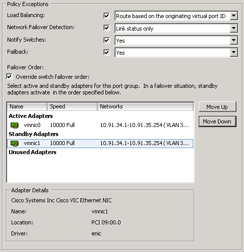
  • Go to the settings of this Portgroup and configure 1 physical NIC-port as active and all others as “standby” (see the screenshot below for an example)
  • Create a second VMkernel Interface and give it the name “vMotion-02″
  • Go to the settings of this Portgroup and configure a different NIC-port as active and all others as “standby

When you will initiate a vMotion multiple NIC ports can be used. Keep in mind that even when you vMotion just 1 virtual machine both links will be used. Also, if you don’t have dedicated links for vMotion you might want to consider using Network I/O Control. vMotion can saturate a link and at least when you’ve set up Network I/O Control and assigned the right amount of shares each type of traffic will get what it has been assigned.

YouTube Video Guide to Multi NIC vMotion setup

http://youtu.be/7njBRF2N0Z8

Example Setup (Thanks to Scott Aisenstat)

http://virtualistmanifesto.com/2011/10/06/vsphere-5-networking-multi-nic-vmotion/

Implementing Microsoft Network Load Balancing in a Virtualized Environment

Network Load Balancing is a feature of recent Microsoft server operating systems, including Windows 2000 Advanced Server, Windows Server 2003, and Windows Server 2008. This clustering technology enables you to improve the scalability and availability of Internet server programs, such as Web servers, proxy servers, DNS servers, FTP servers, virtual private network servers, streaming media servers, and terminal services servers.
In addition, it can detect host failures and automatically redistribute traffic to servers that are still operating.
In a VMware® Infrastructure 3 environment, you can create a cluster for Network Load Balancing using virtual machines on the same host or virtual machines on multiple hosts.

Network Load Balancing Basics

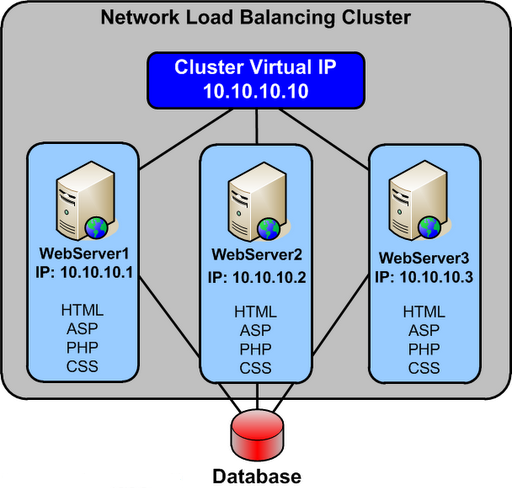
Network Load Balancing is implemented in a special driver installed on each Windows host in a cluster. The cluster presents a single IP address to clients. When client requests arrive, they go to all hosts in the cluster, and an algorithm implemented in the driver maps each request to a particular host. The other hosts in the cluster drop the request. You can set load partitioning to distribute specified percentages of client connections to particular hosts. You also have the option of routing all requests from a particular client to the host that handled that client’s first request.
Hosts in the cluster exchange heartbeat messages so they can maintain consistent information about what hosts are members of the cluster. If a host fails, client requests are rebalanced across the remaining hosts, with each remaining host handling a percentage of requests proportional to the percentage you specified in the initial configuration.

Planning a Network Load Balancing Cluster

Network Load Balancing relies on the fact that incoming packets are directed to all cluster hosts and passed to the Network Load Balancing driver for filtering.
You can configure a Network Load Balancing cluster in one of the following modes:

  • Multicast

Multicast mode allows communication among hosts because it adds a Layer 2 multicast
address to the cluster instead of changing the cluster. Communication among hosts is possible because the hosts retain their original unique media access control (MAC) addresses and already have unique, dedicated IP addresses. However, the address resolution protocol (ARP) reply that is sent by a host in the cluster (in response to an ARP request) maps the cluster’s unicast IP address to its multicast MAC address.
Some routers do not support the resolution of unicast IP addresses to multicast MAC addresses, and they discard the ARP reply. As a result, an administrator must add a static ARP entry in the router, mapping the cluster IP address to its MAC address.

NOTE VMware recommends that you use multicast mode, because unicast mode forces the physical switches on the LAN to broadcast all Network Load Balancing traffic to every machine on the LAN.

  • Unicast

Unicast mode works seamlessly with all routers and Layer 2 switches. However, this mode induces switch flooding, a condition in which all switch ports are flooded with NLB Traffic, even ports to which servers which not involved in NLB are attached. To communicate among hosts, you must have a second virtual adapter for each host.
Normally, switched environments avoid port flooding when a switch learns the MAC addresses of the hosts that are sending network traffic through it. The Network Load Balancing cluster masks the cluster’s MAC address for all outgoing traffic to prevent the switch from learning the MAC address.

On an ESX host, the VMkernel sends a reverse address resolution protocol (RARP) packet each time certain actions occur—for example, when a virtual machine is powered on, when there is a teaming failover, or when certain VMotion operations occur. The RARP packet gives physical switches the MAC address of the virtual machine involved in the action. In a Network Load Balancing cluster environment, after a Network Load Balancing node is powered on, the notification in the RARP packet exposes the MAC address of the cluster NIC. As a result, switches might begin to send all inbound traffic destined for the Network Load Balancing cluster through one switch port to a single node of the cluster.

Because the virtual switch operates with complete data about the underlying MAC addresses of the virtual NICs inside each virtual machine, it always correctly forwards packets containing a MAC address matching that of a running virtual machine. As a result of this behavior, the virtual switch does not forward traffic destined for the Network Load Balancing MAC address outside the virtual environment into the physical network, because it is able to forward it to a local virtual machine

Configuring Network Load Balancing in Windows

  1. Install a Windows operating system that supports Network Load Balancing in your virtual machines.
  2. You should install two virtual NICs in each virtual machine that will be part of the Network Load Balancing cluster. One virtual NIC from each virtual machine is used for Network Load Balancing. The other virtual NIC is used for management of the Windows virtual machine.
  3. Each Network Load Balancing node requires a static IP address to be assigned to the Network Load Balancing‐bound adapter. You need one or more additional static IP addresses to be used as the virtual IP addresses of the Network Load Balancing cluster. Use IP addresses that belong to the same subnet.
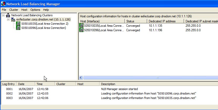
  4. Configure Network Load Balancing options using one of the following: Network Load Balancing Manager or Network Load Balancing Properties dialog box accessed through Network Connections
  5. VMware recommends that you use the Network Load Balancing Manager.
    Using both Network Load Balancing Manager and Network Connections to change Network Load Balancing properties can lead to unpredictable results.

You can use Network Load Balancing Manager from inside a node or from a remote machine that can communicate with all nodes. By default, Network Load Balancing Manager is installed on Windows Server 2003, and you can access it by clicking Settings > Control Panel > Administrative Tools > Network Load Balancing Manager.

Configuring Multicast Mode on VMware Switches

You do not need to take any special steps to configure your ESX host when you are using multicast mode.

Configuring Unicast Mode VMware Switches

This procedure helps prevent RARP packet transmission for the virtual switch as a whole. This setting affects all the port groups that use the switch. To prevent RARP Packet Transmission for a Virtual Switch, do the following

  1. Log on to the VI Client and select the ESX host.
  2. Click the Configuration tab.
  3. Choose Networking and, for the virtual switch, select Properties.
  4. On the Ports tab, select the virtual switch and click Edit.
  5. Click the NIC Teaming tab, set Notify Switches to No.
  6. Click OK and close the vSwitch Properties dialog box

Complete the following steps to prevent RARP packet transmission only for an individual port group. This setting overrides the setting you make for the virtual switch.

  1. Log on to the VI Client and select the ESX host.
  2. Click the Configuration tab.
  3. Choose Networking and, for the virtual switch, select Properties
  4. On the Ports tab, select the port group and click Edit.
  5. Click the NIC Teaming tab, set Notify Switches to No.
  6. Click OK and close the vSwitch Properties dialog box.
  7. Click OK and close the vSwitch Properties dialog box.

What happens to the Packets?

  • The packets/connections simply reach the network adaptor of each machine in the cluster
  • The NLB module sits right on top of the adaptor driver and receives the packet
  • Based on the source ip address of the client and/OR the port number of the client, an algorithm in the NLB module of each server in the cluster decides whether they should pickup this connection or not
  • The algorithm guarantees that only one machine in the cluster will pick up the packet. Think of this as an agree-upon horizontal partitioning strategy. For instance a trivial implementation could be, that in a two machine cluster – machine 1 picks up all connections with odd ip addresses and machine 2 picks up all connections with even IP addresses. This strategy is fool proof and does not require any communication between the machines at all. The actual algorithm is a randomization algorithm that uses more than just the client ip address (based on configuration) to determine whether it should pick up that packet
  • If the NLB module figures that this packet should be picked up by it, it simply passes it through the stack upwards. If not it simply discards the packet at this stage itself
  • NLB supports differential load balancing configurations wherein one can specify unequal distribution of load between machines in a cluster and its algorithm will automatically take care of it
  • NLB also maintains a heartbeat between machines and if any machine is found to be down, it will automatically redistribute the load amongst the remaining machines
  • NLB also supports client_affinity (another name for sticky sessions) where in connections originating from a single IP will be sent to a single source. This can screw up if one is using a reverse-proxy in front of the cluster, since all connections will appear to originate from a single ip address. One should not enable client_affinity if one has a reverse proxy. In most cases if you have a reverse-proxy, the reverse-proxy itself can perform relevant load balancing, so NLB would be redundant

As new machines join or are removed from the cluster, in order for the load to be distributed correctly among all active nodes, the algorithm must be re-executed in an extremely important re-evaluation process called convergence. It is also important to realize that at no time is NLB ever aware of what the load is on any particular cluster node because NLB cannot determine whether a node’s CPU usage is extremely high or that a node has little to no available memory to process a request

Advantages of NLB

  • Network Load Balancing is very efficient and can provide a very big performance improvement for each machine added into the cluster.
  • NLB has a fault tolerance capability. Many other load balancing implementations, such as Round Robin DNS (RRDNS), continue to send requests to servers that have “died” until system administrators pick up on the fact that there is a problem and then manually perform a configuration change. The key is redundancy in addition to load balancing; if any machine in the cluster goes down, NLB will re-balance the incoming requests to the still running servers thus handling scenarios where a power supply has burnt out, a network card has gone bad, the primary hard disk has crashed, etc
  • This level of redundancy increasing the load balancing capability becomes simply a matter of adding machines to the cluster, which results in a practically unlimited application scalability.
  • NLB works with any TCP or UDP application-based protocol. This means that it’s possible to configure a variety of NLB clusters within an organization, and each one can have its own specific function. For example, one cluster may be dedicated to handling all Internet-originated HTTP traffic while another may be used to serve all intranet requests. If the employees have a need for transferring files, there can be a FTP cluster acting as centralized file storage with closely monitored uploads and downloads
  • By far, one of the biggest advantages of NLB is its ease of use. NLB installs only a networking driver component – absolutely no special hardware is required. Not only does this facilitate the deployment of a load balancing solution, but it also significantly reduces costs

References

  • “Checklist: Enabling and configuring Network Load Balancing”

http://go.microsoft.com/fwlink/?LinkId=18371

  • Reasons for using NLB

http://technet2.microsoft.com/windowsserver/en/library/7698646d‐510e‐47f9‐9b09‐b31dec12be3a1033.mspx

VMware vApps

What is a vApp?

You can use VMware vSphere as a platform for running applications, in addition to using it as a platform for running virtual machines. The applications can be packaged to run directly on top of VMware vSphere. The format of how the applications are packaged and managed is called vSphere vApp.
A vApp is a container, like a resource pool and can contain one or more virtual machines. A vApp also shares some functionality with virtual machines. A vApp can power on and power off, and can also be cloned.
In the vSphere Client, a vApp is represented in both the Host and Clusters view and the VM and Template view. Each view has a specific summary page with the current status of the service and relevant summary information, as well as operations on the service.

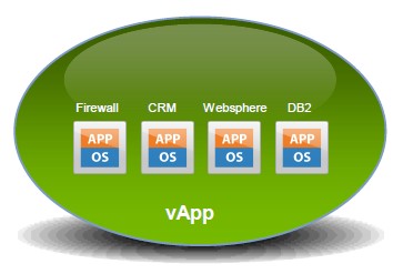
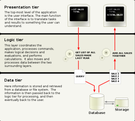
A vApp is basically a resource container for multiple virtual machines that work together as part of a multi-tier application.

The three applications on each server all work together and are mostly dependent on each other for the application to function properly. If one part of the tier became unavailable, the application will typically quit working as it relies on all the tiers for the application to work.

Virtualization can introduce some challenges with multi-tier applications. For example, if one tier is performing poorly due to resource constraints on a host, then the whole application will suffer as a result. Another challenge comes when powering on a host server, as often times one tier relies on another tier to be started first or the application will fail.

VMware introduced vApps as a method to deal with these problems by providing methods for setting power-on options, IP address allocation and resource allocation, and provide application-level customization for all the virtual machines in the vApp. When you configure a vApp in vSphere you specify properties for it, including CPU and memory resources, IP allocation, application information, and start order.

Distribution Format

The distribution format for vApp is OVF.

Note

The vApp metadata resides in the vCenter Server’s database, so a vApp can be distributed across multiple ESXi hosts. This information can be lost if the vCenter Server database is cleared or if a standalone ESXi host that contains a vApp is removed from vCenter Server. You should back up vApps to an OVF package to avoid losing any metadata.
vApp metadata for virtual machines within vApps do not follow the snapshots semantics for virtual machine configuration. So, vApp properties that are deleted, modified, or defined after a snapshot is taken remain intact (deleted, modified, or defined) after the virtual machine reverts to that snapshot or any prior snapshots.

Where can you create a vApp?

After you create a datacenter and add a clustered host enabled with DRS or a standalone host to your vCenter Server system, you can create a vApp.

You can create a vApp under the following conditions.

  • A standalone host is selected in the inventory that is running ESX 3.0 or greater.
  • A cluster enabled with DRS is selected in the inventory.
  • You can create vApps on folders, standalone hosts, resource pools, clusters enabled with DRS, and within other vApps.

Creating a vApp

  • Right click on a cluster or a host and select New vApp

  • Put in a name and select the Inventory location
  • Click Next

  • Adjust resources accordingly and click Next and Finish

Once you are done configuring a vApp, you can add virtual machines (VMs) to it by dragging them using the vSphere client. You can also create resource pools inside of them and nest vApps inside of vApps. If you edit the settings of a VM, select the Options tab, and then select vApp Options, you can enable the vApp functionality for the VM and set individual vApp options for the VM. Once you have created a vApp you can easily export it in Open Virtualization Format (OVF) format, as well as deploy new vApps from one that are already created

  • Go to the vApp in the Hosts and Clusters View and select Edit Settings. You can edit the CPU and memory resource allocation for the vApp

  • Click on Start Order. You can change the order in which virtual machines and nested vApps within a vApp start up and shut down. You can also specify delays and actions performed at startup and shutdown

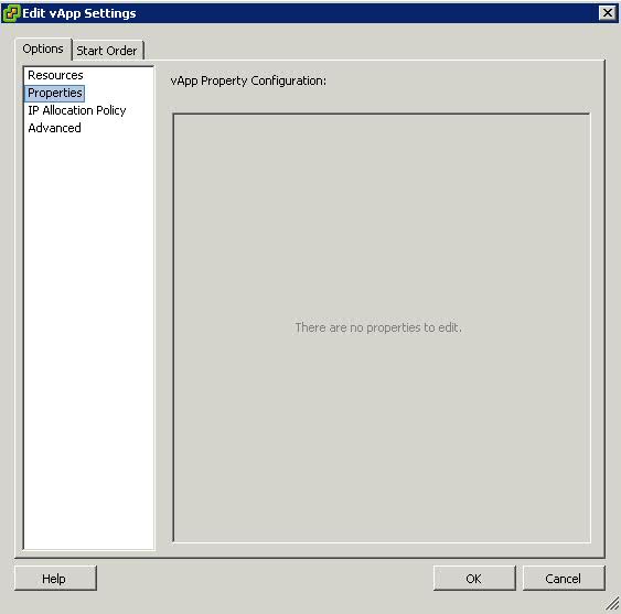
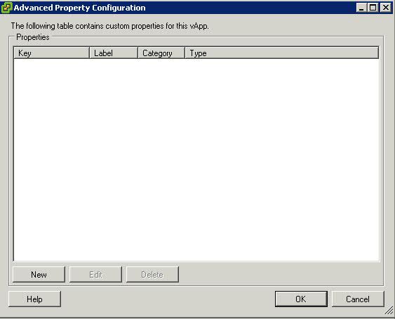
  • Click on Properties. You can edit any vApp property that is defined in Advanced Property Configuration

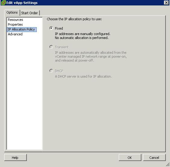
  • Click on IP Allocation Policy. You can edit how IP addresses are allocated for the vApp.

Fixed = IP addresses are manually configured. No automatic allocation is performed

Transient = IP addresses are automatically allocated using IP pools from a specified range when the vApp is powered on. The IP addresses are released when the appliance is powered off.

DHCP = A DHCP server is used to allocate the IP addresses. The addresses assigned by the DHCP server are visible in the OVF environments of virtual machines started in the vApp.

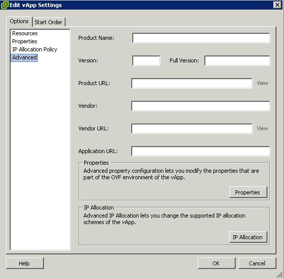
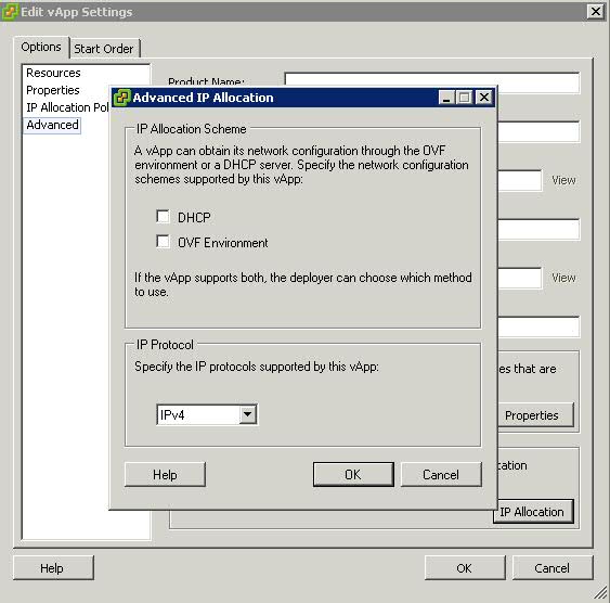
  • Click on Advanced. You can edit and configure advanced settings, such as product and vendor information, custom properties, and IP allocation


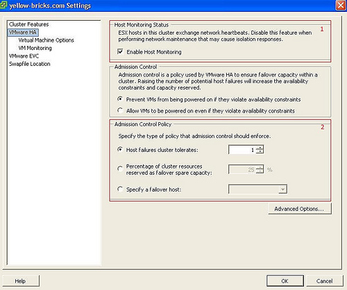
Enabling Host Monitoring in HA Clusters

VMware HA clusters enable a collection of ESX/ESXi hosts to work together so that, as a group, they provide higher levels of availability for virtual machines than each ESX/ESXi host could provide individually. When you plan the creation and usage of a new VMware HA cluster, the options you select affect the way that cluster responds to failures of hosts or virtual machines.
Before creating a VMware HA cluster, you should be aware of how VMware HA identifies host failures andisolation and responds to these situations. You also should know how admission control works so that you can choose the policy that best fits your failover needs. After a cluster has been established, you can customize its behavior with advanced attributes and optimize its performance by following recommended best practices.

How VMware HA works

VMware HA provides high availability for virtual machines by pooling them and the hosts they reside on into a cluster. Hosts in the cluster are monitored and in the event of a failure, the virtual machines on a failed host are restarted on alternate hosts.

Primary and Secondary Hosts in a VMware HA Cluster

When you add a host to a VMware HA cluster, an agent is uploaded to the host and configured to communicate with other agents in the cluster. The first five hosts added to the cluster are designated as primary hosts, and all subsequent hosts are designated as secondary hosts. The primary hosts maintain and replicate all cluster state and are used to initiate failover actions. If a primary host is removed from the cluster, VMware HA promotes another host to primary status.
Any host that joins the cluster must communicate with an existing primary host to complete its configuration (except when you are adding the first host to the cluster). At least one primary host must be functional for VMware HA to operate correctly. If all primary hosts are unavailable (not responding), no hosts can be successfully configured for VMware HA.

Failure Detection and Host Network Isolation

Agents communicate with each other and monitor the liveness of the hosts in the cluster. This is done through the exchange of heartbeats, by default, every second. If a 15-second period elapses without the receipt of heartbeats from a host, and the host cannot be pinged, it is declared as failed. In the event of a host failure, the virtual machines running on that host are failed over, that is, restarted on the alternate hosts with the most available unreserved capacity (CPU and memory.)

Note: In the event of a host failure, VMware HA does not fail over any virtual machines to a host that is in maintenance mode, because such a host is not considered when VMware HA computes the current failover level. When a host exits maintenance mode, the VMware HA service is re-enabled on that host, so it becomes available for failover again.

Host network isolation occurs when a host is still running, but it can no longer communicate with other hosts in the cluster. With default settings, if a host stops receiving heartbeats from all other hosts in the cluster for more than 12 seconds, it attempts to ping its isolation addresses. If this also fails, the host declares itself as isolated from the network.
When the isolated host’s network connection is not restored for 15 seconds or longer, the other hosts in the cluster treat it as failed and attempt to fail over its virtual machines. However, when an isolated host retains access to the shared storage it also retains the disk lock on virtual machine files. To avoid potential data corruption, VMFS disk locking prevents simultaneous write operations to the virtual machine disk files and attempts to fail over the isolated host’s virtual machines fail. By default, the isolated host shuts down its virtual
machines, but you can change the host isolation response to Leave powered on or Power off

Redundancy and Reducing Isolation

If you ensure that your network infrastructure is sufficiently redundant and that at least one network path is available at all times, host network isolation should be a rare occurrence.

Which setting should I use?

  • Shutdown

It depends. Some people prefer “Shut down” because they do not want to use a deprecated host and it will shut down your VMs in a clean manner.

The isolation response is a setting that needs to be taken into account when you create your design. For instance when using an iSCSI array or NFS choosing “leave powered on” as your default isolation response might lead to a split-brain situation depending on the version of ESX used. The reason for this being that the disk lock times out if the iSCSI network is also unavailable. In this case the VM is being restarted on a different host while it is not being powered off on the original host. In a normal situation this should not lead to problems as the VM is restarted and the host on which it runs owns the lock on the VMDK, but for some weird reason when disaster strikes you will not end up in a normal situation but you might end up in an exceptional situation

  • Leave Powered On

Many people prefer to use “Leave powered on” because it reduces the chances of a false positive. A false positive in this case is an isolated heartbeat network but a non-isolated VM network and a non-isolated iSCSI / NFS network.

How does HA knows if the host is isolated or completely unavailable when you have selected “leave powered on”?

HA actually does not know the difference. HA will try to restart the affected VMs in both cases. When the host has failed a restart will take place, but if a host is merely isolated the non-isolated hosts will not be able to restart the affected VMs. This is because of the VMDK file lock; no other host will be able to boot a VM when the files are locked. When a host fails this lock starves and a restart can occur.

Isolation Response Considerations

The default value for isolation/failure detection is 15 seconds. In other words the failed or isolated host will be declared dead by the other hosts in the HA cluster on the fifteenth second and a restart will be initiated by one of the primary hosts.

For now let’s assume the isolation response is “power off”. The “power off”(isolation response) will be initiated by the isolated host 1 second before the das.failuredetectiontime. A “power off” will be initiated on the fourteenth second and a restart will be initiated on the fifteenth second.

Does this mean that you can end up with your VMs being down and HA not restarting them?
Yes, when the heartbeat returns between the 14th and 15th second the “power off” could already have been initiated. The restart however will not be initiated because the heartbeat indicates that the host is not isolated anymore.

How can you avoid this?

Pick “Leave VM powered on” as an isolation response. Increasing the das.failuredetectiontime will also decrease the chances of running in to issues like these.

Basic design principle: Increase “das.failuredetectiontime” to 30 seconds (30000) to decrease the likely-hood of a false positive

Please see the below link for further information on this

http://rickardnobel.se/vmware-ha-das-failuredetectiontime/
Changing the IP Address of the SQL Database Server

If like us, you need to change the IP Address of you vCenter Database server, here are a few pointers

vCenter accesses the DB through an ODBC connection. That’s normally
configured with a FQDN or shortname  rather than an IP address so the
change shouldn’t cause a problem.

You can test it by going to Start –> Administrative Tools –> Data source
(ODBC). Open that up and click on the ‘System DSN’ tab.

Select the vCenter DSN and click on configure. From there you can run
through the wizard without changing anything and at the end there is ‘Test
connection button’. If that works you should be good to go

As long as your DNS servers are up to date there shouldn’t be an issue.

Downgrading License Keys

Purpose

When a new version of a product is released, the older versions are no longer available for purchase. Downgrading a license key allows you to use an older version of a product. If you downgrade a license key, you can revert to the newer version by upgrading the license key.

For more information, see Upgrading license keys in My VMware (2006974).

Only Super Users, Procurement Contacts, and users with Upgrade & Downgrade License Keys permissions can downgrade a license key.

Not all products are eligible for downgrade. When you select Downgrade License Keys from the I want to drop-down, you only see products that can be downgraded.

Notes:

  • The downgrade option is not available for ESXi 4 Single Server to ESXi 3.x.
  • The downgrade option is not available for vSphere Essentials to VI3.
  • For licenses downgraded to ESX 3.x or Site Recovery Manager 1.x, the original licenses are not decreased or affected and the downgrade process cannot be reversed.
  • Workstation 8 licenses can be downgraded to Workstation 7.x licenses.
  • Site Recovery Manager 5 has two different editions: Standard and Enterprise. You can downgrade the Site Recovery Manager 5 Enterprise licenses, but you cannot downgrade Site Recovery Manager 5 Standard licenses.

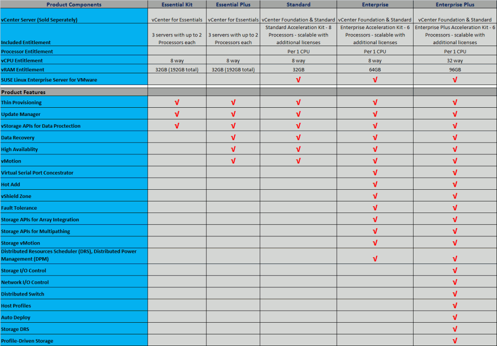
Version Comparison Chart

VMware vSphere Storage Appliance

A VMware vSphere Storage Appliance (VSA) is a virtual appliance that provides small and medium businesses with the benefit of VMware vSphere vMotion and High Availability without requiring shared storage

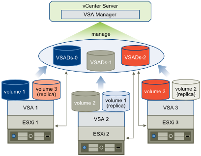
VSA runs on an ESXi host. A VSA cluster is a group of ESXi hosts each running its own VSA instance

A VSA cluster enables the following features

  • Shared Datastores for all hosts in the cluster
  • vMotion and HA
  • Datastore Replication
  • Hardware and Software Datastore failover capabilities

VSA is an alternative to SAN storage

  • A SAN system provides a centralised array of storage
  • A VSA cluster provides a distributed array of storage
  • Elimates the need to purchase expensive SAN storage

VSA Cluster Architecture

The architecture of a VSA cluster includes the physical servers that have local hard disks, ESXi as the operating system of the physical servers, and the vSphere Storage Appliance virtual machines that run clustering services to create volumes that are exported as the VSA datastores.

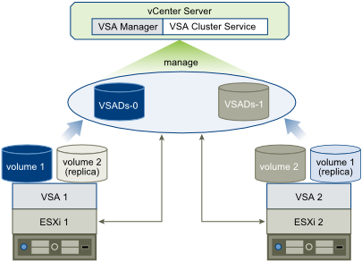
vSphere Storage Appliance supports the creation of a VSA cluster with two or three members. A vSphere Storage Appliance uses the hard disks of an ESXi host to create two volumes of the same size. It exports one of the volumes as a datastore. The other volume is a replica of the volume that is exported by another vSphere Storage Appliance from another host in the VSA cluster

VSA Cluster with 2 hosts

In a VSA cluster with two VSA cluster members, an additional service called VSA cluster service runs on the vCenter Server machine. The service participates as a member in the VSA cluster, but it does not provide storage. To remain online, a VSA cluster requires that more than half of the members are also online. If one instance of a vSphere Storage Appliance fails, the cluster can remain online only if the remaining VSA cluster member and the VSA cluster service are online.

A VSA cluster with 2 members has 2 VSA datastores and maintains a replica of each datastore

VSA Cluster with 3 hosts

A VSA cluster with 3 members has 3 VSA datastores and maintains a replica of each datastore. This configuration does not require the VSA cluster service running on the vCenter Server system

How does it work?

VSA uses the hard disks of the ESXi 5 hosts to maintain a datastore and its replica. VSA created 2 volumes of the same size. It exports one of the volumes as a datastore. The other volume is a replica of the volume that is exported by another VSA from another host in the VSA cluster. A VSA cluster with 2 members has 2 VSA datastores and maintains a replica of each datastore

A VSA cluster with 3 members has 3 datastores and maintains a replica of each datastore

How is Data accessed?

Data is accessed in the VSA cluster using the NFS Version 3 protocol. The NFS exports are used as ESXi datastores which provide shared storage to members in the VSA cluster. The default RAID configuration for the VSA cluster is RAID 10

vCenter server continues to manage the ESXi hosts and the VM’s. vCenter can only manage one VSA cluster at a time

VSA Manager

A VSA cluster is created and managed by the VSA Manager. This is a vCenter Server 5.0 extension that you install on a vCenter Server system. After you install VSA Manager, the VSA Manager tab is displayed in the vSphere client. The VSA Manager is used to do the following

  • Deploying a VSA Cluster
  • Mounting as datastores the volumes that each VSA instance exports
  • Monitoring and maintaining and troubleshooting a VSA cluster

More Information

VMware VSA Documentation

http://www.vmware.com/support/pubs

What is the vSphere Web Client?

What is the vSphere Web Client?

  • This is a funky new feature in vSphere 5
  • An alternative to using the vSphere Client and a web-based interface to vCenter or a VMware ESXi host
  • Supports Firefox and IE Browsers on multiple O/S platforms (Windows and Linux)
  • Customisable Interface
  • Advanced Search Functionality
  • Partners and Users can add features and capabilities
  • Requires Adobe Flash Player

What can it be used for?

  •  Managing VMs
  • Creating VMs
  • Performing VM operations
  • Configuring VM Resources
  • Viewing all vSphere objects
  • Performing basic health monitoring
  • Supplying a remote console
  • Managing vSphere apps through the web

Where do you install it from?

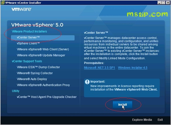
The only difference between installing this to the vSphere Client is selecting an HTTP and a HTTPS Port. By default the HTTP and HTTPS ports are 9090 and 9443 although be careful using 9443 as this is used as a storage I/O Port by VMware. Possible conflict

Installation

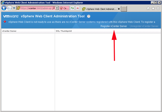
  • Before you can connect to a vCenter Server Instance, you must register the vCenter Server Instance.
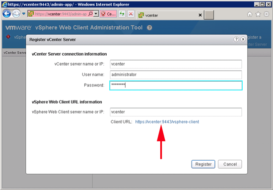
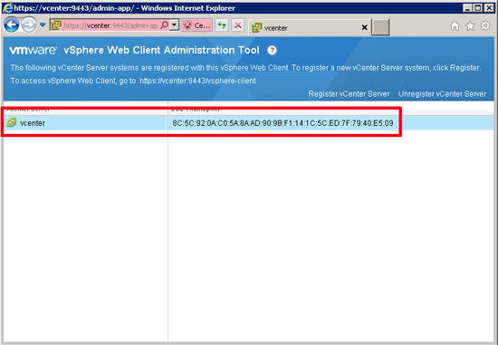
  • Select Start > Programs > VMware > VMware vSphere Web Client > vSphere Administration Application and click Register vCenter Server

  •  Use this tool to register one or more vCenter Instances. This tool cannot be run remotely. The User must have Admin rights to the vCenter Server Instance

  • Ignore the Client Certificate warning
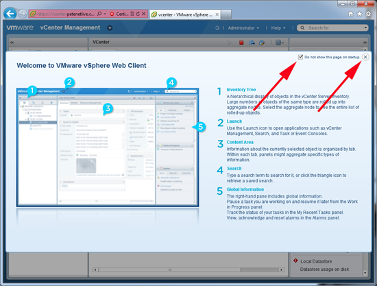
  • The next screen is the final screen showing you are configured.

  • Open a Web Browser window and type in the URL HTTP:vCenterSever:9443/vSphere-client
  • Put in Server, Username and Password

This Service runs under a service called vCenter Inventory Service – Always make sure this is running or you may get an error when you connect.

Unable to add new LUNS on VMware 4.1 U2

Problem

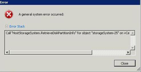
This week we have upgraded our hosts to VMware ESXi 4.1.0, 582267. Our storage guy has given us 2 x 2TB LUN’s but I was unable to add them as per screen-print below. Previously he has created 2TB LUNs and these have been fine

Unable to read partition information from disk

Solution

It seems Update 2 enforces the maximum LUN size, which is 2TB minus 512 Bytes with vSphere 4.x. Depending on the storage system, 2 TB could be either 2.000 GB (marketing size) or 2.048GB (technical size). The above mentioned maximum relates to the technical size, so with the storage system you have, you may need to configure 2.047GB max.

See Also

http://virtualgeek.typepad.com/virtual_geek/2009/06/vsphere-and-2tb-luns-changes-from-vi3x.html

External I/O workload detected on shared datastore running Storage I/O Control (SIOC)

This alarm may appear in the vCenter vSphere Client. A warning message similar to one of these may also appear in the vCenter vSphere Client:

  • Non-VI Workload detected on the datastore
  • An external I/O workload is detected on datastore XYZABC

This informational event alerts the user of a potential misconfiguration or I/O performance issue caused by a non-ESX workload. It is triggered when Storage I/O Control (SIOC) detects that a workload that is not managed by SIOC is contributing to I/O congestion on a datastore that is managed by SIOC. (Congestion is defined as a datastore’s response time being above the SIOC threshold.) Specific situations that can trigger this event include:

  • The host is running in an unsupported configuration.
  • The storage array is performing a system operation such as replication or RAID reconstruction.
  • VMware Consolidated Backup or vStorage APIs for Data Protection are accessing a snapshot on the datastore for backup purposes.
  • The storage media (spindles, SSD) on which this datastore is located is shared with volumes used by non-vSphere workloads
SIOC continues to work during these situations. This event can be ignored in many cases and you can disable the associated alarm once you have verified that none of the potential misconfigurations or serious performance issues are present in your environment. As explained in detail below, SIOC ensures that the ESX workloads it manages are able to compete for I/O resources on equal footing with external workloads. This event notifies the user of what is happening, provides the user with the opportunity to better understand what is going on, and highlights a potential opportunity to correct or optimize the infrastructure configuration.

NOTE: At this time, SIOC is not supported with NFS storage or with Raw Device Mappings (RDM) virtual disks. This includes RDM’s used for MSCS (Microsoft cluster server) also datastores with multiple extents. This alarm could occur if these storage object are configured.

Example Scenario 1:

A /vmfs/volumes/shared-LUN datastore is accessible across multiple hosts. Some hosts are running ESX version 4.1 or later and others are either running an older version or are outside the control domain of vCenter Server.

Example Scenario 2:

The array being used for vSphere is also being used for non-vSphere workloads. The non-vSphere workloads are accessing a storage volume that is on the same disk spindles as the affected datastore.

Impact

When SIOC detects that datastore response time has exceeded the threshold, it typically throttles the ESX workloads accessing the datastore to ensure that the workloads with the highest shares get preference for I/O access to the datastore and lower I/O response time. However, such throttling is not appropriate when workloads not managed by SIOC are accessing the same storage media. Throttling in this case would result in the external workload getting more and more bandwidth, while the vSphere workloads get less and less. Therefore, SIOC detects the presence of such external workloads, and as long as they are present while the threshold is being exceeded, SIOC competes with the interfering workload by curtailing its usual throttling activity.

SIOC automatically detects when the interference goes away and resumes its normal behavior. In this way, SIOC is able to operate correctly even in the presence of interference. The vCenter Server event is notifying the user that SIOC has noticed and handled the interference from external workloads.

Note: When an external workload is acting to drive the datastore response time above the SIOC threshold, the external workload might cause I/O performance issues for vSphere workloads. In most cases, SIOC can automatically and safely manage this situation. However, there may be an opportunity to improve performance by changing some aspects of your configuration. The next section provides guidance on this

These unsupported configurations can result in the event:

  • One or more hosts accessing the datastore are running an ESX version older than 4.1.
  • One or more hosts accessing the datastore are not managed by vCenter Server.
  • Not all of the hosts accessing the datastore are managed by the same vCenter Server.
  • The storage media (spindles, SSD) where this datastore is located are shared with other datastores that are not SIOC enabled.
  • Datastores in the configuration have multiple extents.

Ensure that you are running a supported configuration:

  • Can you disable and successfully re-enable congestion management for the affected datastore?

Disable and attempt to re-enable congestion management for the affected datastore. If the event occurred because the configuration includes hosts that are running an older version of ESX and the hosts are managed by the same vCenter Server, vCenter Server detects the problem and does not allow you to re-enable congestion management. When the older hosts are updated to ESX 4.1 or later, or the hosts are disconnected from the affected datastore, you can enable congestion management.

  • Are hosts that are not managed by this vCenter Server accessing the affected datastore?
If disabling and re-enabling congestion management for the affected datastore does not solve the problem, other hosts that are not managed by this vCenter Server might be accessing the datastore.

Verify that the datastore is shared across hosts that are managed by different vCenter Server systems or are not managed hosts. If so, perform one of these actions:

  • Do all datastores in the configuration that share the same physical storage media (spindles, SSD) have the same SIOC configuration?
    All datastores that share physical storage media must share the same SIOC configuration — all enabled or all disabled. In addition, if you have modified the default congestion threshold setting, all datastores that share storage media must have the same setting.
  • Are any SIOC-enabled datastores in the configuration backed up by multiple extents?
    SIOC-enabled datastores must not be backed up by multiple extents.

If none of the above scenarios apply to your configuration and you have determined that you are running a supported configuration, but are still seeing this event, investigate possible I/O throttling by the storage array.

If an environment is known to have shared access to datastores or performance constraints, it may be preferable to disable the Alarm in vCenter Server. For more information, see Working with Alarms in the vSphere 4.1 Datacenter Administration Guide.

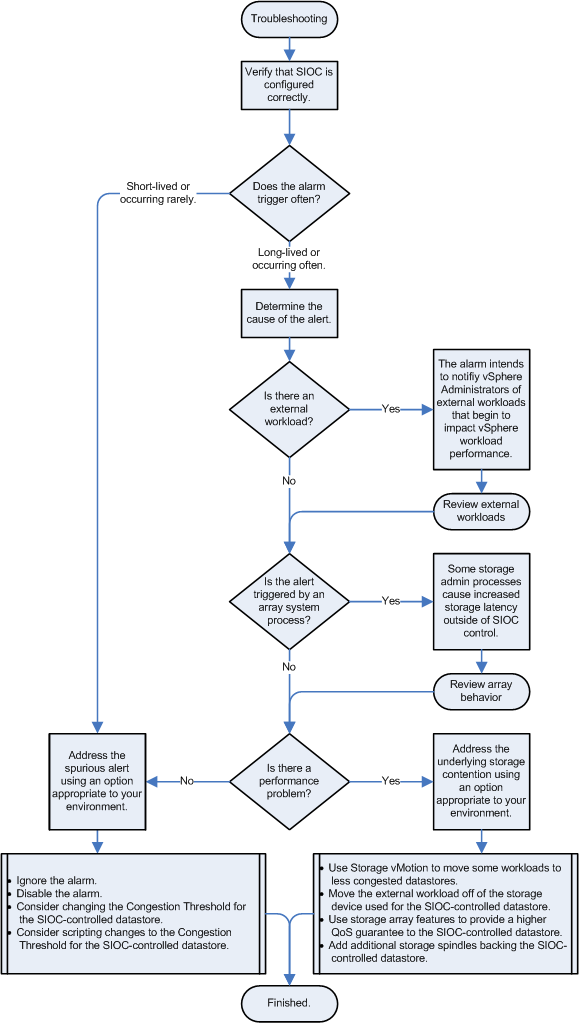
Flowchart for Troubleshooting