Archive for Certification

(VAAI) vSphere Storage APIs for Array Integration

help-sm

What is VAAI?

VAAI helps storage vendors provide hardware assistance in the form of API components to accelerate VMware I/O operations that are more efficiently run within the storage which reduces CPU in the host

How do I know if my storage array supports VAAI?

To determine if your storage array support VAAI, see the Hardware Compatibility List or consult your storage vendor.
To enable the hardware acceleration on the storage array, check with your storage vendor. Some storage arrays require explicit activation of hardware acceleration support.

vSphere 5

With vSphere 5.0, support for the VAAI capabilities has been enhanced and additional capabilities have been introduced

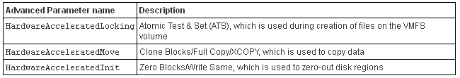
  1. vSphere thin provisioning – Enabling the reclamation of unused space and monitoring of space usage for thin provisioned LUNs.
  2. Hardware Acceleration for NAS – Enables NAS arrays to integrate with VMware to offload operations such as offline cloning, cold migrations and cloning from templates
  3. SCSI standardisation – T10 compliancy for full copy, block zeroing and hardware assisted locking.
  4. Hardware assisted Full Copy – Enabling the storage to make full copies of data in the array
  5. Hardware assisted Block zeroing – Enabling the array to zero out large numbers of blocks
  6. Hardware assisted locking – Providing an alternative mechanism to protect VMFS metadata

vSphere thin provisioning

Historically the 2 major challenges of thin provisoned LUNs have been the reclamation of dead space and the challenges surrounding the monitoring of space usage. VAAI thin provisoning introduces the following. For Thin Provisioning, enabling/disabling occurs on the array and not on the ESXi host

  • Dead Space reclamation informs the array about the datastore space that is freed when files/disks are deleted or removed from the datastore by general deletion or storage vMotion. The array then reclaims the space

  • Out of Space Condition monitors the space on thin provisioned LUNs to prevent running out of space. A new advanced warning has been added to vSphere


 Hardware Acceleration for NAS

Hardware acceleration for NAS will enable faster provisioning and the use of thick virtual disks through new VAAI capabilities

  • Full File Clone – Similar to Full Copy. Enables virtual disks to be cloned by the NAS Device
  • Reserve Space – Enables creation of thick virtual disk files on NAS
  • Lazy File Clone- Emulates the Linked Clone functionality on VMFS datastores. Allows the NAS device to create native snapshots to conserve space for VDI environments.
  • Extended Statistics – Provides more accurate space reporting when using Lazy File Clone

Prior to vSphere 5, a virtual disk was created as a thin provisioned disk, not even enabling the creation of a thick disk. Starting with vSphere 5, VAAI NAS extensions enable NFS vendors to reserve space for an entire virtual disk.

SCSI standardisation – T10 compliancy for full block, block zeroing and hardware assisted locking

vSphere 4.1 introduced T10 compliancy for block zeroing enabling vendors to utilise the T10 standards with the default shipped plugin. vSphere 5 introduces enhanced support for T10 enabling the use of VAAI capabilities without the need to install a plug-in as well as enabling support for many storage devices.

Hardware-Accelerated Full Copy

Enables the storage array to make complete copies of a data set without involving the ESXi host, thereby reducing storage (and network traffic depending on your configuration) traffic between the host and the array. The XSET command offloads the process of copying VMDK blocks which can reduce the time in cloning, deploying from templates and svMotions of VMs.

Hardware-Accelerated Block Zeroing

This feature enables the storage array to zero out a large number of blocks. This eliminates redundant host write commands. Performance improvements can be seen related to creating VMs and formatting virtual disks

Hardware Assisted Locking

Permits VM level locking without the use of SCSI reservations, using VMware’s Compare and Write command. Enables disk locking per sector as opposed to the entire LUN, providing a more efficient way to alter a metadata related file. This feature improves metadata heavy operations, such as concurrently powering on multiple VMs.

How do I know if VAAI is enabled through the vClient?

  • In the vSphere Client inventory panel, select the host
  • Click the Configuration tab, and click Advanced Settings under Software.
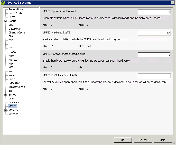
  • Click VMFS3
  • Select VMFS3.HardwareAcceleratedLocking
  • Check that this option is set to 1 (enabled)

vaai

  • Click DataMover
  • DataMover.HardwareAcceleratedMove
  • DataMover.HardwareAcceleratedInit

datamover

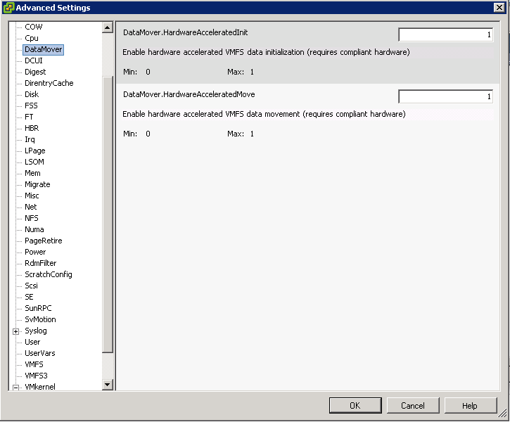
  • Note: These 3 options are enabled by default.

vaai

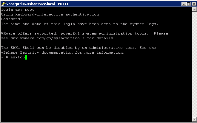
How do I know if VAAI is enabled through the command line

  • Type the following commands
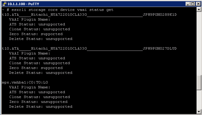
  • esxcli storage core device vaai status get -d naa.abcdefg
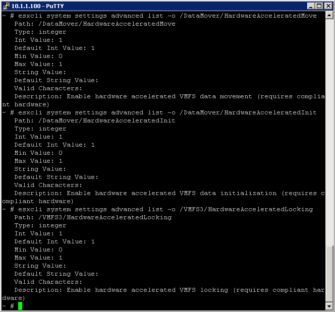
  • esxcli system settings advanced list -o /DataMover/HardwareAcceleratedMove
  • esxcli system settings advanced list -o /DataMover/HardwareAcceleratedInit
  • esxcli system settings advanced list -o /VMFS3/HardwareAcceleratedLocking
  • esxcli storage core plugin list -N VAAI – displays plugins for VAAI
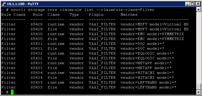
  • esxcli storage core plugin list -N Filterdisplays VAAI filter

Examples

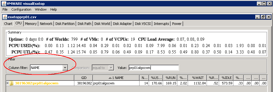
To check the VAAI Status

Capture

To determine if VAAI is enabled, check is Int Value is set to 1

VAAI

What happens if I have VAAI enabled on the host but some of my disk arrays do not support it?

When storage devices do not support or provide only partial support for the host operations, the host reverts to its native methods to perform the unsupported operations.

Hardware Acceleration Support Status

For each storage device and datastore, the vSphere Client displays the hardware acceleration support status in the Hardware Acceleration column of the Devices view and the Datastores view. The status values are

  • Unknown
  • Supported
  • Not Supported

The initial value is Unknown. The status changes to Supported after the host successfully performs the offload operation. If the offload operation fails, the status changes to Not Supported. When storage devices do not support or provide only partial support for the host operations, your host reverts to its native methods to perform unsupported operations

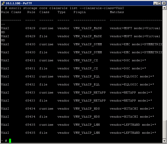
How to add Hardware Acceleration Claim Rules

To implement the hardware acceleration functionality, the Pluggable  Storage Architecture (PSA) uses a combination of special array  integration plug-ins, called VAAI plug-ins, and an array integration  filter, called VAAI filter. The PSA automatically attaches the VAAI  filter and vendor-specific VAAI plug-ins to those storage devices that  support the hardware acceleration

You need to add two claim rules, one for the VAAI filter and another for the VAAI plug-in. For the new claim rules to be active, you first define the rules and then load them into your system.

  • Define a new claim rule for the VAAI filter
  • esxcli –server servername storage core claimrule add –claimrule-class=Filter –plugin=VAAI_FILTER
  • Define a new claim rule for the VAAI plug-in
  • esxcli –server servername storage core claimrule add –claimrule-class=VAAI
  • Load both claim rules by running the following commands:
  • esxcli –server servername storage core claimrule load –claimrule-class=Filter
  • esxcli –server servername storage core claimrule load –claimrule-class=VAAI
  • Run the VAAI filter claim rule, Only this one needs to be loaded
  • esxcli –server servername storage core claimrule run –claimrule-class=Filter

Examples

VAAI2

VAAI3

Installing a NAS plug-in

  • Place your host into the maintenance mode.
  • Get and set the host acceptance level
  • esxcli software acceptance get
  • esxcli software acceptance set –level=value
  • The value can be one of the following: VMwareCertified, VMwareAccepted, PartnerSupported, CommunitySupported. Default is PartnerSupported
  • Install the VIB package
  • esxcli software vib install -v|–viburl=URL
  • The URL specifies the URL to the VIB package to install. http:, https:, ftp:, and file: are supported.
  • Verify the Plugin is installed
  • esxcli software vib list
  • Reboot your host

VMware RDMs

What is RAW Device Mapping?

A Raw Device Mapping allows a special file in a VMFS volume to act as a proxy for a raw device. The mapping file contains metadata used to manage and redirect disk accesses to the physical device. The mapping file gives you some of the advantages of a virtual disk in the VMFS file system, while keeping some advantages of direct access to physical device characteristics. In effect it merges VMFS manageability with raw device access

A raw device mapping is effectively a symbolic link from a VMFS to a raw LUN. This makes LUNs appear as files in a VMFS volume. The mapping file, not the raw LUN is referenced in the virtual machine configuration. The mapping file contains a reference to the raw LUN.

Note that raw device mapping requires the mapped device to be a whole LUN; mapping to a partition only is not supported.

Uses for RDM’s

  • Use RDMs when VMFS virtual disk would become too large to effectively manage.

For example, When a VM needs a partition that is greater than the VMFS 2 TB limit is a reason to use an RDM. Large file servers, if you choose to encapsulate them as a VM, are a prime example. Perhaps a data warehouse application would be another. Alongside this, the time it would take to move a vmdk larger than this would be significant.

  • Use RDMs to leverage native SAN tools

SAN snapshots, direct backups, performance monitoring, and SAN management are all possible reasons to consider RDMs. Native SAN tools can snapshot the LUN and move the data about at a much quicker rate.

  • Use RDMs for virtualized MSCS Clusters

Actually, this is not a choice. Microsoft Clustering Services (MSCS) running on VMware VI require RDMs. Clustering VMs across ESX hosts is still commonly used when consolidating hardware to VI. VMware now recommends that cluster data and quorum disks be configured as raw device mappings rather than as files on shared VMFS

Terminology

The following terms are used in this document or related documentation:

  • Raw Disk — A disk volume accessed by a virtual machine as an alternative to a virtual disk file; it may or may not be accessed via a mapping file.
  • Raw Device — Any SCSI device accessed via a mapping file. For ESX Server 2.5, only disk devices are supported.
  • Raw LUN — A logical disk volume located in a SAN.
  • LUN — Acronym for a logical unit number.
  • Mapping File — A VMFS file containing metadata used to map and manage a raw device.
  • Mapping — An abbreviated term for a raw device mapping.
  • Mapped Device — A raw device managed by a mapping file.
  • Metadata File — A mapping file.
  • Compatibility Mode — The virtualization type used for SCSI device access (physical or virtual).
  • SAN — Acronym for a storage area network.
  • VMFS — A high-performance file system used by VMware ESX Server.

Compatibility Modes

Physical Mode RDMs

  • Useful if you are using SAN-aware applications in the virtual machine
  • Useful to run SCSI target based software
  • Physical mode is useful to run SAN management agents or other SCSI target based software in the virtual machine
  • Physical mode for the RDM specifies minimal SCSI virtualization of the mapped device, allowing the greatest flexibility for SAN management software. In physical mode, the VMkernel passes all SCSI commands to the device, with one exception: the REPORT LUNs command is virtualized, so that the VMkernel can isolate the LUN for the owning virtual machine. Otherwise, all physical characteristics of the underlying hardware are exposed.

Virtual Mode RDMs

  • Advanced file locking for data protection
  • VMware Snapshots
  • Allows for cloning
  • Redo logs for streamlining development processes
  • More portable across storage hardware, presenting the same behavior as a virtual disk file

Setting up RDMs

  •  Right click on the Virtual Machine and select Edit Settings
  • Under the Hardware Tab, click Add
  • Select Hard Disk
  • Click Next
  • Click Raw Device Mapping

If the option is greyed out, please check the following.

http://kb.vmware.com/RDM Greyed Out

  • From the list of SAN disks or LUNs, select a raw LUN for your virtual machine to access directly.
  • Select a datastore for the RDM mapping file. You can place the RDM file on the same datastore where your virtual machine configuration file resides,
    or select a different datastore.
  • Select a compatibility mode. Physical or Virtual
  • Select a virtual device node
  • Click Next.
  • In the Ready to Complete New Virtual Machine page, review your selections.
  • Click Finish to complete your virtual machine.

Note: To use vMotion for virtual machines with enabled NPIV, make sure that the RDM files of the virtual machines are located on the same datastore. You cannot perform Storage vMotion or vMotion between datastores when NPIV is enabled.

Configure Port Groups to properly isolate network traffic and VLAN Tagging

VLANs provide for logical groupings of stations or switch ports, allowing communications as if all stations or ports were on the same physical LAN segment. Confining broadcast traffic to a subset of the switch ports or end users saves significant amounts of network bandwidth and processor time.
In order to support VLANs for VMware Infrastructure users, one of the elements on the virtual or physical network has to tag the Ethernet frames with 802.1Q tag as per below

The most common tagging is 802.1Q, which is an IEEE standard that nearly all switches support. The tag is there to identify which VLAN the layer 2 frame belongs to. vSphere can both understand these tags (receive them) as well as add them to outbound traffic (send them)

There are three different configuration modes to tag (and untag) the packets for virtual machine frames

  1. VST (VLAN range 1-4094)
  2. VGT (VLAN ID 4095 enables trunking on port group)
  3. EST (VLAN ID 0 Disables VLAN tagging on port group)

1. VST (Virtual Switch Tagging)

This is the most common configuration. In this mode, you provision one port group on a virtual switch for each VLAN, then attach the virtual machine’s virtual adapter to the port group instead of the virtual switch directly.

The virtual switch port group tags all outbound frames and removes tags for all inbound frames. It also ensures that frames on one VLAN do not leak into a different VLAN.

Use of this mode requires that the physical switch provide a trunk. E.g The ESX host network adapters must be connected to trunk ports on the physical switch.

The port groups connected to the virtual switch must have an appropriate VLAN ID specified

switchport trunk encapsulation dot1q
switchport mode trunk
switchport trunk allowed vlan x,y,z
spanning-tree portfast trunk

Note: The Native VLAN is not tagged and thus requires no VLAN ID to be set on the ESX/ESXi portgroup.

2. VGT (Virtual Guest Tagging)

You may install an 802.1Q VLAN trunking driver inside the virtual machine, and tags will be preserved between the virtual machine networking stack and external switch when frames are passed from or to virtual switches. Use of this mode requires that the physical switch provide a trunk

3. EST (External Switch Tagging)

You may use external switches for VLAN tagging. This is similar to a physical network, and VLAN configuration is normally transparent to each individual physical server.
There is no need to provide a trunk in these environments.

All VLAN tagging of packets is performed on the physical switch.

ESX host network adapters are connected to access ports on the physical switch.

The portgroups connected to the virtual switch must have their VLAN ID set to 0.

See this example snippet of a code from a Cisco switch port configuration:

switchport mode access
switchport access vlan x

Virtual Distributed Switches

In vSphere, there’s a new networking feature which can be configured on the distributed virtual switch (or DVS). In VI3 it is only possible to add one VLAN to a specific port group in the vSwitch. in the DVS, you can add a range of VLANs to a single port group. The feature is called VLAN trunking and it can be configured when you add a new port group. There you have the option to define a VLAN type, which can be one of the following:

  • None
  • VLAN
  • VLAN trunking
  • Private VLAN. But this can only be done on the DVS, not on a regular vSwitch. See screendumps below (both from vSphere environment)

VLAN7

The VLAN policy allows virtual networks to join physical VLANs.

  • Log in to the vSphere Client and select the Networking inventory view.
  • Select the vSphere distributed switch in the inventory pane.
  • On the Ports tab, right-click the port to modify and select Edit Settings.
  • Click Policies.
  • Select the VLAN Type to use.
  • Select VLAN Trunking
  • Select a VLAN ID between 1- 4094
  • Note: Do not use VLAN ID 4095

What is a VLAN Trunk?

A VLAN trunk is a port on a physical switch that has the ability to listen and pass traffic for multiple VLANs. Trunks are used primarily to pass traffic between multiple switches.

In Cisco networks, trunking is a special function that can be assigned to a port, making that port capable of carrying traffic for any or all of the VLANs accessible by a particular switch. Such a port is called a trunk port, in contrast to an access port, which carries traffic only to and from the specific VLAN assigned to it. A trunk port marks frames with special identifying tags (either ISL tags or 802.1Q tags) as they pass between switches, so each frame can be routed to its intended VLAN. An access port does not provide such tags, because the VLAN for it is pre-assigned, and identifying markers are therefore unnecessary.

A quick note on the relationship between VLANs and vSwitch port groups. A VLAN can contain multiple port groups, but a port group can only be associated with one VLAN at any given time. A prerequisite for VLAN functionality on a vSwitch (vSS or vDS) is that the vSwitch uplinks must be connected to a trunk port on the physical switch. This trunk port will also need to include the associated VLAN ID range, enabling the physical switch to pass VLAN tags to the ESXi host. So why is any of this important? A trunk port can store and distribute multiple VLAN tags, enabling multiple traffic types to flow independently (at least logically), across the same uplink or group of uplinks in the case of teamed NICs

Use case for using VLAN trunking would be if you have multiple VLANs in place for logical separation or to isolate your VM traffic but you have a limited amount of physical uplink ports dedicated for your ESXi hosts

Networking Policies

Policies set at the standard switch or distributed port group level apply to all of the port groups on the standard switch or to ports in the distributed port group. The exceptions are the configuration options that are overridden at the standard port group or distributed port level.

  • Load Balancing and Failover Policy
  • VLAN Policy
  • Security Policy
  • Traffic Shaping Policy
  • Resource Allocation Policy
  • Monitoring Policy
  • Port Blocking Policies
  • Manage Policies for Multiple Port Groups on a vSphere Distributed Switch

Useful Post (Thanks to Mohammed Raffic)

http://www.vmwarearena.com/2012/07/vlan-tagging-vst-est-vgt-on-vmware.html?goback=.gde_42087_member_239011765

DRS

What is DRS?

A DRS cluster is a collection of ESXi hosts and associated virtual machines with shared resources and a shared interface. Before you can obtain the benefits of cluster-level resource management you must create a DRS cluster.
When you add a host to a DRS cluster, the host’s resources become part of the cluster’s resources. In addition to this aggregation of resources, with a DRS cluster you can support cluster-wide resource pools and enforce cluster-level resource allocation policies. The following cluster-level resource management capabilities are also available.

DRS must use Shared Storage and a vMotion network

  • Load Balancing

The distribution and usage of CPU and memory resources for all hosts and virtual machines in the cluster are continuously monitored. DRS compares these metrics to an ideal resource utilization given the attributes of the cluster’s resource pools and virtual machines, the current demand, and the imbalance target. It then performs (or recommends) virtual machine migrations accordingly. When you first power on a virtual machine in the cluster, DRS attempts to maintain proper load balancing by either placing the virtual machine on an appropriate host or making a recommendation.

  • Power management

When the vSphere Distributed Power Management (DPM) feature is enabled, DRS compares cluster- and host-level capacity to the demands of the cluster’s virtual machines, including recent historical demand. It places (or recommends placing) hosts in standby power mode if sufficient excess capacity is found or powering on hosts if capacity is needed. Depending on the resulting host power state recommendations, virtual machines might need to be migrated to and from the hosts as well.

  • Affinity Rules

You can control the placement of virtual machines on hosts within a cluster, by
assigning affinity rules.

DRS, EVC and FT

Depending on whether or not Enhanced vMotion Compatibility (EVC) is enabled, DRS behaves differently when you use vSphere Fault Tolerance (vSphere FT) virtual machines in your cluster.

DRS

Migration Recommendations

The system supplies as many recommendations as necessary to enforce rules and balance the resources of the cluster. Each recommendation includes the virtual machine to be moved, current (source) host and destination host, and a reason for the recommendation. The reason can be one of the following:

  • Balance average CPU loads or reservations
  • Balance average memory loads or reservations
  • Satisfy resource pool reservations
  • Satisfy an affinity rule.
  • Host is entering maintenance mode or standby mode.

Note: If you are using the vSphere Distributed Power Management (DPM) feature, in addition to migration recommendations, DRS provides host power state recommendations

Using DRS Affinity Rules

You can control the placement of virtual machines on hosts within a cluster by using affinity rules. You can create two types of rules.

  • VM-Host

Used to specify affinity or anti-affinity between a group of virtual machines and a group of hosts. An affinity rule specifies that the members of a selected virtual machine DRS group can or must run on the members of a specific host DRS group. An anti-affinity rule specifies that the members of a selected virtual machine DRS group cannot run on the members of a specific host DRS group.

  • VM-VM

Used to specify affinity or anti-affinity between individual virtual machines. A rule specifying affinity causes DRS to try to keep the specified virtual machines together on the same host, for example, for performance reasons. With an anti-affinity rule, DRS tries to keep the specified virtual machines apart, for example, so that when a problem occurs with one host, you do not lose both virtual machines. When you add or edit an affinity rule, and the cluster’s current state is in violation of the rule, the system continues to operate and tries to correct the violation. For manual and partially automated DRS clusters, migration recommendations based on rule fulfillment and load balancing are presented for approval. You are not required to fulfill the rules, but the corresponding recommendations remain until the rules are fulfilled.

To check whether any enabled affinity rules are being violated and cannot be corrected by DRS, select the cluster’s DRS tab and click Faults. Any rule currently being violated has a corresponding fault on this page.
Read the fault to determine why DRS is not able to satisfy the particular rule. Rules violations also produce a log event.

DRS Automation Levels

Someone at my work asked me about these levels and wanted an explanation for the Aggressive Level. He said he envisaged machines continually moving around in a state of perpetual motion. Lets find out!

Just as a note, you access DRS Automation Level Settings by right clicking on the cluster and selecting Edit Settings, then selecting VMware DRS

There are 3 settings

  1. Manual – vCenter will suggest migration recommendations for virtual machines
  2. Partially Automated – Virtual machines will be placed onto hosts at power on and vCenter will suggest migration recommendations for virtual machines
  3. Fully Automated – Virtual machines will be automatically places on to hosts when powered on and will be automatically migrated from one host to another to optimize resource usage

For Fully Automated there is a slider called Migration threshold

You can move the slider to use one of the five levels

  • Level 1 – Apply only five-star recommendations. Includes recommendations that must be followed to satisfy cluster constraints, such as affinity rules and host maintenance. This level indicates a mandatory move, required to satisfy an affinity rule or evacuate a host that is entering maintenance mode.
  • Level 2 – Apply recommendations with four or more stars. Includes Level 1 plus recommendations that promise a significant improvement in the cluster’s load balance.
  • Level 3 – Apply recommendations with three or more stars. Includes Level 1 and 2 plus recommendations that promise a good improvement in the cluster’s load balance.
  • Level 4 – Apply recommendations with two or more stars. Includes Level 1-3 plus recommendations that promise a moderate improvement in the cluster’s load balance.
  • Level 5 – Apply all recommendations. Includes Level 1-4 plus recommendations that promise a slight improvement in the cluster’s load balance.

Some interesting facts

  • DRS has a threshold of up to 60 vMotion events per hour
  • It will check for imbalances in the cluster once every five minutes

vCenter Console

DRS

When the Current host load standard deviation exceeds the target host load standard deviation, DRS will make recommendations and take action based on the automation level and migration threshold

The target host load standard deviation is derived from the migration threshold setting. A load is considered imbalanced as long as the current value exceeds the migration threshold.

Each host has a host load metric based upon the CPU and memory resources in use. It is described as the sum of expected virtual machine loads divided by the capacity of the host. The LoadImbalanceMetric also known as the current host load standard deviation is the standard deviation (average of averages) of all host load metrics in a cluster.

DRS decides what virtual machines are migrated based on simulating a move and recalculating the current host load standard deviation and making a recommendation. As part of this simulation, a cost benefit and risk analysis is performed to determine best placement. DRS will continue to perform simulations and will make recommendations as long as the current host load exceeds the target host load.

Properly size virtual machine automation levels based on Application Requirements

  • When a virtual machine is powered on, DRS is responsible for performing initial placement. During initial placement, DRS considers the “worst case scenario” for a VM. For example, when a new server that has been overspec’d gets powered on, DRS will actively attempt to identify a host that can guarantee that CPU and RAM to the VM. This is due to the fact that historical resource utilization statistics for the VM are unavailable. If DRS cannot find a cluster host able to accommodate the VM, it will be forced to “defragment” the cluster by moving other VMs around to account for the one being powered on. As such, VMs should be be sized based on their current workload.
  • When performing an assessment of a physical environment as part of a vSphere migration, an administrator should leverage the resource utilization data from VMware Capacity Planner in allocating resources to VMs.
  • Do not set VM reservations too high as this can affect DRS Balancing DRS might not have excess resources to move VMs around
  • Group Virtual Machines for a multi-tier service into a Resource Pool
  • Don’t forget to calculate memory overhead when sizing VMs into clusters
  • Use Resource Settings such as Shares, Limits and Reservations only when necessary

Automation

  • You might want to keep VMs on the same host if they are part of a tiered application that runs on multiple VMs, such as a web, application, or database server.
  • You might want to keep VMs on different hosts for servers that are clustered or redundant, such as Active Directory (AD), DNS, or web servers, so that a single ESX failure does not affect both servers at the same time. Doing this ensures that at least one will stay up and remain available while the other recovers from a host failure.
  • You might want to separate servers that have high I/O workloads so that you do not overburden a specific host with too many high-workload servers.
  • Keep servers like vCenter, the vCenter DB and Domain Controllers as a high priority

VMware vCLI for vSphere 5

VMware vCLI Instructions

The vSphere Command-Line Interface (vSphere CLI) command set allows you to run common system administration commands against ESX/ESXi systems from any machine with network access to those systems. You can also run most vSphere CLI commands against a vCenter Server system and target any ESX/ESXi system that vCenter Server system manages. vSphere CLI includes the ESXCLI command set, vicfg- commands, and some other commands.

  • Download and Install vCLI
  • http://www.vmware.com/support/developer/vcli/
  • Right click on the vCLI icon and select Run as Administrator
  • Navigate to c:\Program Files (x86)\VMware\VMware vSphere CLI\bin
  • You will see the below vCLI commands (Note the .pl extension on the end)

vcli2

  • An example of running a command would be as per below with vifs.pl
  • Type vifs.pl –help to see the associated switches for this command

vifs

  • Try typing vifs.pl –server esxihostserver –listdc

vifs3

  • Another example of this command as per below screenprints shows how you can create a folder on a Datstore
  • vifs.pl –server esxiserver –mkdir “[Datastore] test”

vifs4

Documentation

vSphere Command-Line Interface Documentation

Getting Started with vSphere Command-Line Interfaces

vSphere Command‐Line Interface Concepts and Examples

vSphere Command‐Line Interface Reference

YouTube Video

You Tube Video

Running Commands on Windows.

In order to stop having to put in credentials everytime you run a command you can can the following

save_session.pl –server esxiserver01 –username usera –password passswordxyz –savesessionfile c:\temp\vclisessionfile

The next time you run a command you can type the following

esxcli –server MyESXiHost –sessionfile c:\temp\vclisessionfile storage core filesystem list

vCLI Poster

http://blogs.vmware.com/tp/files/vmware-management-with-vcli-5.0.pdf

Port Group Security

Security Options

portsecurity

Promiscuous Mode

Promiscuous mode eliminates any reception filtering that the virtual network adapter would perform so that the guest operating system receives all traffic observed on the wire. By default, the virtual network adapter cannot operate in promiscuous mode.

Although promiscuous mode can be useful for tracking network activity, it is an insecure mode of operation, because any adapter in promiscuous mode has access to the packets regardless of whether some of the packets are received only by a particular network adapter. This means that an administrator or root user within a virtual machine can potentially view traffic destined for other guest or host operating system

Note

In some situations, you might have a legitimate reason to configure a standard switch to operate in promiscuous mode (for example, if you are running network intrusion detection software or a packet sniffer

MAC Address Changes

The setting for the MAC Address Changes option affects traffic that a virtual machine receives.

When the option is set to Accept, ESXi accepts requests to change the effective MAC address to other than the initial MAC address.

When the option is set to Reject, ESXi does not honor requests to change the effective MAC address to anything other than the initial MAC address, which protects the host against MAC impersonation. The port that the virtual adapter used to send the request is disabled and the virtual adapter does not receive any more frames until it changes the effective MAC address to match the initial MAC address. The guest operating system does not detect that the MAC address change was not honored.

Note

The iSCSI initiator relies on being able to get MAC address changes from certain types of storage. If you are using ESXi iSCSI and have iSCSI storage, set the MAC Address Changes option to Accept.

In some situations, you might have a legitimate need for more than one adapter to have the same MAC address on a network—for example, if you are using Microsoft Network Load Balancing in unicast mode. When Microsoft Network Load Balancing is used in the standard multicast mode, adapters do not share MAC addresses.

MAC address changes settings affect traffic leaving a virtual machine. MAC address changes will occur if the sender is permitted to make them, even if standard switches or a receiving virtual machine does not permit MAC address chan

Forged Transmits

The setting for the Forged Transmits option affects traffic that is transmitted from a virtual machine.

When the option is set to Accept, ESXi does not compare source and effective MAC addresses.

To protect against MAC impersonation, you can set this option to Reject. If you do, the host compares the source MAC address being transmitted by the operating system with the effective MAC address for its adapter to see if they match. If the addresses do not match, ESXi drops the packet.

The guest operating system does not detect that its virtual network adapter cannot send packets by using the impersonated MAC address. The ESXi host intercepts any packets with impersonated addresses before they are delivered, and the guest operating system might assume that the packets are dropped

Note

This option is enabled by default, because it is occasionally needed to avoid software licensing problems. For example, if software on a physical machine is licensed to a specific MAC address, it will not work in a virtual machine because the VM’s MAC address is different. In this case, allowing forged transmits enables you to use the software by forging the VM’s MAC address.

However, allowing forged transmits poses a security risk.If an administrator has only authorized specific MAC addresses to enter the network, an intruder may be able to change his unauthorized MAC address to an authorized one

RESXTOP and ESXTOP

ESXTOP and RESXTOP

Are used to analyze real-time performance data from an individual ESX or ESXi server.

The fundamental difference between resxtop and esxtop is that you can use resxtop remotely, whereas you can start extop only through the ESXi Shell of a local ESXi host.

You can start either utility in one of three modes:

  • Interactive (default)
  • Batch
  • Replay

Running ESXTOP/RESXTOP

Type esxtop/resxtop into one of the following consoles

  • Putty
  • vMA (vSphere Management Assistant) virtual appliance.
  • vCLI
  • Power CLI

esxtop59

When running RESXTOP you will have to specify the ESX or ESXi server hostname, username, and password, as you see below

What you will see first

  • Global Statistics

  • Up time

The elapsed time since the server has been powered on.

  • Number of worlds

The total number of worlds on ESX(i) Server (Like Processes)

  • CPU load average

The arithmetic mean of CPU loads in 1 minute, 5 minutes, and 15 minutes, based on 6-second samples. CPU load accounts the run time and ready time for all the groups on the host.

A load average of 0.50 means that the physical CPUs on the ESXi system
are half utilized.

A load average of 1.00 means that the physical CPUs on the ESXi system
are fully utilized.

A load average of 2.00 means that means that the physical CPUs on the ESXi system
are doubly utilized and the ESXi system might need twice as many physical CPUs as are currently available.

Accessing the 8 different displays

You’ll find that ESXTOP/RESXTOP has 8 different “displays” that show CPU, interrupt, memory, network, disk adapter, disk interface, disk VM, and power management. These are accessed by typing the letters below

Commands by letter

esxtop

Running esxtop in Batch Mode

  • Log into the host using whichever console you feel comfortable with. E.g. Putty
  • Type esxtop
  • Type V (Capital V) to just show the VMs

esxtop1

  • By default you are on the CPU Screen. If you then type f (lower case) you can toggle between what CPU fields to view. Type the letter to activate the relevant field

esxtop2

  • Press any key to return to the main screen and now press m (lower case) for Memory and then press f to see the fields. Type the letter to activate the relevant field

esxtop3

  • Press any key to return to the main screen then type n (lower case) for Network and type f to see the fields. Type the letter to activate the relevant field

esxtop4

  • Press any key to return to the main screen and now press v (lower case) for VM Disk and then press f to see the fields. Type the letter to activate the relevant field.

esxtop5

  • Now you have selected all your fields, you need to press W (Capital W) to save your settings then press Enter

esxtop6

  • You should see the following screen flash up quickly

esxtop7

  • Type q to quit and go back to your normal command line

esxtop8

  • You now need to run it in batch mode and save the results to a .csv file:
  • Type esxtop -b -a -d 2 -n 1800 > /tmp/esxtopcapture.csv

Where “-b” stands for batch mode, “-d 2″ is a delay of 2 seconds and “-n 1800″ are 3600 iterations. In this specific case esxtop will log all metrics for 1 Hour. If you want to record all metrics make sure to add “-a” to your string.

esxtopbatch

Analysing Data

You can use multiple tools to analyze the captured data. Underlined are links to the software

  1. VisualEsxtop
  2. perfmon
  3. excel
  4. esxplot

VisualEsxtop

VisualEsxtop is an enhanced version of resxtop and esxtop. VisualEsxtop can connect to VMware vCenter Server or ESX hosts, and display ESX server stats with a better user interface and more advanced features.

Features

  1. Live connection to ESX host or vCenter Server
  2. Flexible way of batch output
  3. Load batch output and replay them
  4. Multiple windows to display different data at the same time
  5. Line chart for selected performance counters
  6. Flexible counter selection and filtering
  7. Embedded tooltip for counter description
  8. Color coding for important counters

Instructions

  • Once it is download you must make sure that Java is installed or VisualEsxtop will not run. We have JRE 6 Update 29 installed. You can check this by running cmd.exe and typing java

java

  • If you don’t have Java installed correctly then you will get the following message

esxtop60

  • For Windows, navigate to your VisualEsxtop folder and run the VisualEsxtop.bat file

esxtop56

  • It should open the below application
  • Click File > Load Batch Output and open your CSV output file from running ESXTOP in Batch Mode

esxtop57

  • You can then filter as well

esxtop58

https://labs.vmware.com/flings/visualesxtop

http://blogs.vmware.com/kb/2013/09/using-visualesxtop-to-troubleshoot-performance-issues-in-vsphere-2.html

Perfmon

  • On your Windows Server, click Start > Run > Type perfmon
  • Right click on the graph and select “Properties”.

esxtop50

  • Select the “Source” tab.
  • Select the “Log files:” radio button from the “Data source” section.
  • Click the “Add” button.

esxtop51

  • Select the CSV file created by esxtop and click “OK”.

esxtop52

  • Click the “Apply” button.
  • Optionally: reduce the range of time over which the data will be displayed by using the sliders under the “Time Range” button.
  • Select the “Data” tab.
  • Remove all Counters.

esxtop53

  • Click “Add” and select appropriate counters. When you click on some of the counters, you can select the instance or VM/Machine you want to monitor directly
  • Click Add

esxtop54

  • Click “OK”
  • Click “OK”
  • You should now see the graph of values

esxtop55

Using ESXPLOT

Please see the below link for instructions

  1. Run: esxplot
  2. Click File -> Import -> Dataset
  3. Select file and click “Open”
  4. Double click host name and click on metric

http://www.electricmonk.org.uk/2012/09/05/esxplot/

Using MS Excel

Within Excel it is also possible to import the data as a CSV. You need to be careful of the size of the file though as the amount of captured data is sometimes quite large so you might want to limit it by first importing it into perfmon and then select the correct timeframe and counters and export this to a CSV. You can import the CSV as per below instructions

  1. Run: Excel
  2. Click on “Data”
  3. Click “Import External Data” and click “Import Data”
  4. Select “Text files” as “Files of Type”
  5. Select file and click “Open”
  6. Make sure “Delimited” is selected and click “Next”
  7. Deselect “Tab” and select “Comma”
  8. Click “Next” and “Finish

Looking at esxtop values and results (Realtime)

General CPU Statistics

First visible CPU Statistics

CPUesxtop

Optional Fields for CPU Performance Monitoring

General Memory Statistics

 First Visible Memory Statistics

esxtop5

Optional Fields for Memory Performance Monitoring

esxtopmem5

General Disk Statistics

General Network Statistics

esxtopnetwork

Running ESXTOP in Replay Mode

In replay mode, esxtop replays resource utilization statistics collected using vm-support.

After you prepare for replay mode, you can use esxtop in this mode.

In replay mode, esxtop accepts the same set of interactive commands as in interactive mode and runs until no more snapshots are collected by vm-support to be read or until the requested number of iterations are completed.

To run in replay mode, you must prepare for replay mode.

  • Run vm-support in snapshot mode on the ESX service console
  • Type vm-support -S -d duration -I interval
  • -S = Snapshot mode, prompts for the delay between updates, in seconds
  • -R = Path to the vm-support collected snapshot’s directory
  • Unzip and untar the resulting tar file so that esxtop can use it in replay mode.
  • tar -xf /root/esx*.tgz
  • Now run the following
  • esxtop -R root/vm-support*

http://www.vmwarearena.com/2012/08/esxtop-replay-mode.html

5 of the best posts for analysing results and statistics

http://www.yellow-bricks.com/esxtop/

http://communities.vmware.com/docs/DOC-9279

http://www.vmware.com/pdf/esx2_using_esxtop.pdf

http://simongreaves.co.uk/blog/esxtop-guide

http://communities.vmware.com/docs/DOC-5240

Analysing CPU/RAM/Network/Performance

http://communities.vmware.com/docs/DOC-3930

Enhanced vMotion Compatibility

What is EVC?

EVC is short for Enhanced VMotion Compatibility. EVC allows you to migrate virtual machines between different generations of CPUs.

What is the benefit of EVC?

Because EVC allows you to migrate virtual machines between different generations of CPUs, with EVC you can mix older and newer server generations in the same cluster and be able to migrate virtual machines with VMotion between these hosts. This makes adding new hardware into your existing infrastructure easier and helps extend the value of your existing hosts. With EVC, full cluster upgrades can be achieved with no virtual machine downtime whatsoever. As you add new hosts to the cluster, you can migrate your virtual machines to the new hosts and retire the older hosts

How do I use EVC?

EVC is enabled for a cluster in the VirtualCenter or vCenter Server inventory. After it is enabled, EVC ensures that migration with VMotion is possible between any hosts in the cluster. Only hosts that preserve this property can be added to the cluster.

How does it work?

After EVC is enabled, all hosts in the cluster are configured to present the CPU features of a user-selected processor type to all virtual machines running in the cluster. This ensures CPU compatibility for VMotion even though the underlying hardware might be different from host to host. Identical CPU features are exposed to virtual machines regardless of which host they are running on, so that the virtual machines can migrate between any hosts in cluster

Which CPUs are compatible with each EVC mode?

To determine the EVC modes compatible with your CPU, search the VMware Compatibility Guide. Search for the server model or CPU family, and click the entry in the CPU Series column to display the compatible EVC modes.

Note: EVC is required for Fault Tolerant Machines to interoperate and integrate with DRS.

Instructions for enabling

  • Right click on the Datacenter object in vCenter and select New Cluster
  • Type a name for the new cluster
  • Enable HA and DRS as you require

  • Select which EVC CPU Type you need

  • You then have to choose the processor mode you need. See below 2 diagrams

  • In order to know what mode to choose, please follow the below article

http://kb.vmware.com/kb/1003212

EVC and General Application Performance White Paper

http://www.vmware.com/files/pdf/techpaper/VMware-vSphere-EVC-Perf.pdf

Calculate Available Resources and VMware HA (High Availability) Slots

Admission Control Settings

Within a cluster we use Admission control to ensure that sufficient resources exist to provide failover protection. Admission control is also used to ensure that virtual machine resource reservations are protected

Admission Control Policies

  • Host Failures the Cluster tolerates
  • Percentage of Cluster Resources reserved as failover spare capacity
  • Specify Failover Hosts

Host Failures the Cluster tolerates

What is a Slot?

A slot is a logical representation of the memory and CPU resources that satisfy the requirements for any powered-on virtual machine in the cluster

In vCenter Server 4.0, the slot size is now shown in vSphere Client on the Summary tab of the cluster

How is the Slot calculated?

  • VMware HA determines how many slots are available in each ESX/ESXi host based on the host’s CPU and memory capacity.
  • It then determines how many ESX/ESXi hosts can fail in the cluster with at least as many slots as powered on virtual machines.

Default Reservation Values

Slot size is comprised of two components, CPU and memory

VMware calculates the memory component by obtaining the memory reservation (If set) plus memory overhead, of each powered-on virtual machine and selecting the largest value. There is no default value for the memory reservation.

If a virtual machine does not have reservations, meaning that the reservation is 0, default values are used as listed below

  • 0 MB of RAM and 256 MHz CPU speed are used for vSphere 4 and Prior
  • 0 MB of RAM and 32MHz for CPU for vSphere 5.0 and above
  • When no memory reservation is specified for a virtual machine, the largest memory overhead for any virtual machine in the cluster will be used as the default slot size value for memory

Advanced Settings for CPU and Memory Slot Size

  • das.vmMemoryMinMB <value>

This options/value pair overrides the default memory slot size value used for admission control for VMware HA where <value> is the amount of RAM in MB to be used for the calculation if there are no larger memory reservations. By default this value is set to 256MB. This is the minimum amount of memory in MB sufficient for any VM in the cluster to be usable

  • das.vmCPUMinMHz <value>

This options/value pair overrides the default CPU slot size value used for admission control for VMware HA where <value> is the amount of CPU in MHz to be used for the calculation if there are no larger memory reservations. By default this value is set to 256MHz

Maximum Upper Bound Advanced Settings for Slot Sizing

If your cluster contains any virtual machines that have much larger reservations than the others, they will  distort slot size calculation. To avoid this, you can specify an upper bound for the CPU or memory component of the slot size by using the das.slotcpuinmhz or das.slotmeminmb advanced attributes, respectively.

Keep in mind that when you are low on resources this could mean that you are not able to power-on this high reservation VM as resources are fragmented throughout the cluster instead of located on a single host.

  • das.slotmeminmb <value>

This option defines the maximum bound on the memory slot size. If this option is used, the slot size is the smaller of this value or the maximum memory reservation plus memory overhead of any powered-on virtual machine in the cluster.

  • das.slotcpuinmhz <value>

This option defines the maximum bound on the CPU slot size. If this option is used, the slot size is the smaller of this value or the maximum CPU reservation of any powered on virtual machine in the cluster

HA Failover Capacity

There are lots of questions surrounding VMware’s HA (High Availability), especially when users see a message stating there are “Insufficient resources to satisfy HA failover.” It is worth making the effort to understand capacity calculations. In current versions of ESX(i)and earlier, the following calculation applies for failover capacity.

Failover Capacity is determined using a slot size value that is calculated on the cluster. Slots are calculated by a combination of the total CPU and Memory that are in the physical hosts. The calculation for failover capacity works as follows:

Let’s say you have 4 ESX servers in your VMware HA cluster and Configured Failover capacity on the cluster is set to 1.

Physical memory in the hosts is as follows:

ESX1 = 16 GB
ESX2 = 24 GB
ESX3 = 32 GB
ESX4 = 32 GB

In the cluster you have 24 VM’s each configured and running. Of the 24 VM’s running, determine the VM which has the highest “configured memory”. For this example let’s say this is 2GB. All other VMs are configured with less or equal to 2GB.

With this information we can now do the calculation:

1. Pick the ESX host which has the least amount of RAM. In this case it is ESX1 and the minimum amount of RAM is = 16 GB

2. Divide the value found in step 1 with value for the maximum RAM in a VM. In my example this gives us 8 (16 divided by 2). This means we have 8 slots available per ESX host in the cluster.

3. Since we have 4 hosts and the configured failover capacity for the cluster is 1, we are left with 3 hosts in a failure situation. Hence the total number of VMs that can be powered on these 3 servers is 24 VMs. (i.e. 8 multiplied by 3 = 24)

4. If the total number of VMs in the cluster exceeds 24 then it will give us “Insufficient resources to satisfy HA failover” and the “current failover capacity will be shown as 0″. If the number is less than 24, we should not get this message.

Note: If you are still seeing the message and you have less VM’s running than in the calculation allows for, check both the CPU and Memory reservations on both VM’s and resource pools, as this can skew the calculation. You should avoid unnecessary memory or cpu reservations on VM’s as this can cause these types of errors to occur, because we have to ensure that the resource is available.

Host Failures?

What happens if you set the number of allowed host failures to 1?
The host with the most slots will be taken out of the equation. If you have 8 hosts with 90 slots in total but 7 hosts each have 10 slots and one host 20 this single host will not be taken into account. Worst case scenario! In other words the 7 hosts should be able to provide enough resources for the cluster when a failure of the “20 slot” host occurs.

And of course if you set it to 2 the next host that will be taken out of the equation is the host with the second most slots and so on

How can we get round distorted Slot Sizes causing HA errors?

There are multiple ways to fix, or get around this calculation. The most common are as follows:

  • Set the Disable – “ Power on Vms that violate availability constraints” in the configuration of the cluster. In this case it ignores the above calculation and will try to power on as many VM’s as possible in case of HA failover. If this is the option chosen you can also set restart priority in the ‘Virtual Machine Options’ section of the cluster configuration. This way any high priority VM’s are powered on first, and then the lower priority up to the point where we cannot power any further VM’s on

  • If you have one VM which is configured with a very high amount of memory, you can either lower its configured memory, or take it out of the cluster and run it on any other standalone ESX host. This will increase the number of slots available with the current hardware
  • Increase the amount of RAM on servers so that there are more slots available with the current RAM reservations.
  • Remove any CPU reservations on any VM(s) that are greater than the max speed of the processors in the hosts.
  • With vSphere this is something that’s configurable. If you have just one VM with a really high reservation you can set the following advanced settings to lower the slot size being used during these calculations: das.slotCpuInMHz or das.slotMemInMB. To avoid not being able to power on the VM with high reservations these VM will take up multiple slots. Keep in mind that when you are low on resources this could mean that you are not able to power-on this high reservation VM as resources are fragmented throughout the cluster instead of located on a single host.

What if you don’t want to…

  • Disable strict admission control
  • Mess around with setting advanced settings for Minimum Memory and CPU Slot size
  • Lower the VM Memory reservation

There is also the option of

  • Creating a memory reservation on a Resource Pool and putting the VM in here

Why?

High Availability ignores resource pools reservation settings when calculating the slot size, so if a single VM is placed in a resource pool with memory reservation configured, it will have the same effect on resource allocation as per VM memory reservation, but does not affect the HA slot size.

By creating a resource pool with a substantial memory setting you can avoid decreasing the consolidation ratio of the cluster and still guarantee the virtual machine its resources. You need to be careful though. Creating a Resource Pool for each VM would be a catastrophic way of managing multiple high memory configured VMs and probably should be carried out when you have 1 or 2 VMs that have this type of configuration

Percentage of Cluster Resources Reserved as Failover

With the Percentage of Cluster Resources reserved for Failover Spare Capacity, vSphere HA ensures that a specified percentage of aggregate CPU and memory is reserved for Failover

vSphere HA uses reservations of CPU and Memory if they have been set. If not they use a default value of 0MB Memory and 256MHz CPU

With this policy HA does the following

  • Calculates the total resource requirement for all powered on machines in the cluster
  • Calculates the total host resources available for the virtual machines
  • Calculates the current CPU and Memory failover capacity for the cluster
  • Determines if either the current CPU failover or current memory failover is less than the corresponding failover capacity
  • If so Admission Control disallows the operation

Example

Specify Failover Hosts

If you choose this option, be aware that you will lose one whole host to be put aside for capcity

HA Slot sizes in the vSphere 5 Web Client

You now have the ability to set slot size for “Host failures tolerated” through the vSphere Web Client

slot

More Information

There are great articles on the below webpages regarding HA Slot sizing and calculation

http://www.vmwarewolf.com/ha-failover-capacity/#more

and this article walking you through an example

http://www.vladan.fr/ha-slot-sizes/

HA Slot sizes in the vSphere 5 Web Client

http://www.yellow-bricks.com/2012/09/12/whats-new-vsphere-5-1-high-availability/

VDS Port Group – Port Bindings

There are 3 types of Port Binding

  1. Static Binding
  2. Dynamic Binding
  3. Ephemeral Binding

Static Binding

When you connect a virtual machine to a port group configured with static binding, a port is immediately assigned and reserved for it, guaranteeing connectivity at all times. The port is disconnected only when the virtual machine is removed from the port group. You can connect a virtual machine to a static-binding port group only through vCenter Server.

Dynamic Binding

In a port group configured with dynamic binding, a port is assigned to a virtual machine only when the virtual machine is powered on and its NIC is in a connected state. The port is disconnected when the virtual machine is powered off or the virtual machine’s NIC is disconnected. Virtual machines connected to a port group configured with dynamic binding must be powered on and off through vCenter.

Dynamic binding can be used in environments where you have more virtual machines than available ports, but do not plan to have a greater number of virtual machines active than you have available ports. For example, if you have 300 virtual machines and 100 ports, but never have more than 90 virtual machines active at one time, dynamic binding would be appropriate for your port group.

Note: Dynamic binding is deprecated in ESXi 5.0.

Ephemeral Binding

In a port group configured with ephemeral binding, a port is created and assigned to a virtual machine by the host when the virtual machine is powered on and its NIC is in a connected state. The port is deleted when the virtual machine is powered off or the virtual machine’s NIC is disconnected.

You can assign a virtual machine to a distributed port group with ephemeral port binding on ESX/ESXi and vCenter, giving you the flexibility to manage virtual machine connections through the host when vCenter is down. Although only ephemeral binding allows you to modify virtual machine network connections when vCenter is down, network traffic is unaffected by vCenter failure regardless of port binding type.

Note: Ephemeral port groups should be used only for recovery purposes when you want to provision ports directly on host bypassing vCenter Server, not for any other case. This is true for several reasons:

The disadvantage is that if you configure ephemeral port binding your network will be less secure. Anybody who will gain host access can create rogue virtual machine and place it on the network or to move VMs between networks. The security hardening guide even recommends to lower the number of ports for each distributed portgroup so there are none unused.

AutoExpand (New Feature)

Note: vSphere 5.0 has introduced a new advanced option for static port binding called Auto Expand. This port group property allows a port group to expand automatically by a small predefined margin whenever the port group is about to run out of ports. In vSphere 5.1, the Auto Expand feature is enabled by default.

In vSphere 5.0 Auto Expand is disabled by default. To enable it, use the vSphere 5.0 SDK via the managed object browser (MOB):

  • In a browser, enter the address http://vc-ip-address/mob/.
  • When prompted, enter your vCenter Server username and password.
  • Click the Content link.

expand

  • In the left pane, search for the row with the word rootFolder.
  • Open the link in the right pane of the row. The link should be similar to group-d1 (Datacenters).
  • In the left pane, search for the row with the word childEntity. In the right pane, you see a list of datacenter links.
  • Click the datacenter link in which the vDS is defined.
  • In the left pane, search for the row with the word networkFolder and open the link in the right pane. The link should be similar to group-n123 (network).
  • In the left pane, search for the row with the word childEntity. You see a list of vDS and distributed port group links in the right pane.
  • Click the distributed port group for which you want to change this property.
  • In the left pane, search for the row with the word config and click the link in the right pane.
  • In the left pane, search for the row with the word autoExpand. It is usually the first row.
  • Note the corresponding value displayed in the right pane. The value should be false by default.
  • In the left pane, search for the row with the word configVersion. The value should be 1 if it has not been modified.
  • Note the corresponding value displayed in the right pane as it is needed later.
  • Note: I found mine said AutoExpand=true and ConfigVersion=3

expand2

  • Go back to the distributed port group page.
  • Click the link at the bottom of the page that reads ReconfigureDv<PortGroup>_Task
  • A new window appears.

expand3

  • In the Value field, find the following lines and adjust them to the values you recorded earlier

<spec>
<configVersion>3</configVersion>

  • And scroll to the end and find and adjust this

<autoExpand>true</autoExpand>
</spec>

  • where configVersion is what you recorded in step 15.
  • Click the Invoke Method link.
  • Close the window.
  • Repeat Steps 10 through 14 to verify the new value for autoExpand.

Useful VMware Article

http://kb.vmware.com/selfservice/microsites/search.do?language=en_US&cmd=displayKC&externalId=1022312

Useful Blog on why to use Static Port Binding on vDS Switches

http://blogs.vmware.com/vsphere/2012/05/why-use-static-port-binding-on-vds-.html