Archive for Certification

Understand and apply LUN masking using PSA-related commands

index

What is LUN Masking?

LUN (Logical Unit Number) Masking is an authorization process that makes a LUN available to some hosts and unavailable to other hosts.LUN Masking is implemented primarily at the HBA (Host Bus Adapter) level. LUN Masking implemented at this level is vulnerable to any attack that compromises the HBA. Some storage controllers also support LUN Masking.

LUN Masking is important because Windows based servers attempt to write volume labels to all available LUN’s. This can render the LUN’s unusable by other operating systems and can result in data loss.

How to MASK on a VMware ESXi Host

  • Step 1: Identifying the volume in question and obtaining the naa ID
  • Step 2: Run the esxcli command to associate/find this naa ID with the vmhba identifiers
  • Step 3: Masking the volume when you want to preserve data from the VMFS volumes for later use or if the volume is already deleted
  • Step 4: Loading the Claim Rules
  • Step 5: Verify that the claimrule has loaded:
  • Step 6: Unclaim the volume in question
  • Step 7: Check Messages
  • Step 8: Unpresent the LUN
  • Step 9: Rescan all hosts
  • Step 10 Restore normal claim rules
  • Step 11: Rescan Datastores

Step 1

  • Check in both places as listed in the table above that you have the correct ID
  • Note: Check every LUN as sometimes VMware calls the same Datastore different LUN Numbers and this will affect your commands later

claim3

  • Example Below

LUN

  • Make a note of the naa ID

Step 2

  • Once you have the naa ID from the above step, run the following command
  • Note we take the : off
  • -L parameter will show a compact list of paths

CLAIM2

  • Example below

lun3

  • We can see there are 2 paths to the LUN called C0:T0:L40 and C0:T1:L40
  • C=Channel, T=Target, L=LUN
  • Next we need to check and see what claim rules exist in order to not use an existing claim rule number
  • esxcli storage core claimrule list
  • Note I had to revert to the vSphere 4 CLI command as I am screenprinting from vSphere 5 not 4!

claimrule

Step 3

  • At this point you should be absolutely clear what LUN number you are using!

claim4

  • Next, you can use any rule numbers for the new claim rule that isn’t in the list above and pretty much anything from 101 upwards
  • In theory I have several paths so i should do this exercise for all of the paths

claim5

Step 4

claim6

  • The Class for those rules will show as file which means that it is loaded in /etc/vmware/esx.conf but it isn’t yet loaded into runtime.

Step 5

claim

  • Run the following command to see those rules displayed twice, once as the file Class and once as the runtime Class

Step 6

claim8

  • Before these paths can be associated with the new plugin (MASK_PATH), they need to be disassociated from the plugin they are currently using. In this case those paths are claimed by the NMP plugin (rule 65535). This next command will unclaim all paths for that device and then reclaim them based on the claimrules in runtime.

claim

Step 7

  • Check Messages

claim9

  • See example below

grep

  • Refresh the Datastore and you should see it vanish from the host view
  • Run the following command to check it now shows no paths
  • esxcfg-mpath -L | grep naa.60050768028080befc00000000000050 again will now show no paths

Step 8

  • Now get your Storage Team to remove the LUN from the SAN

Step 9

  • Rescan all hosts and make sure the Datastore has gone

Step 10

  • To restore normal claimrules, perform these steps for every host that had visibility to the LUN, or from all hosts on which you created rules earlier:

claim10

  • Run esxcli corestorage claimrule load
  • Run esxcli corestorage claimrule list
  • Note that you do not see/should not see the rules that you created earlier.

claimrule

  • Perform a rescan on all ESX hosts that had visibility to the LUN. If all of the hosts are in a cluster, right-click the cluster and click Rescan for Datastores. Previously masked LUNs should now be accessible to the ESX hosts

Step 11

  • Next you may have to follow the following KB Article if you find you have these messages in the logs or you cannot add new LUNs
  • Run the following commands on all HBA Adapters

unclaim

Useful Video of LUN Masking

http://www.youtube.com/watch?feature=player_embedded&v=pyNZkZmTKQQ

Useful VMware Docs (ESXi4)

http://kb.vmware.com/selfservice/microsites/search.do?language=en_US&cmd=displayKC&externalId=1029786

http://kb.vmware.com/selfservice/microsites/search.do?language=en_US&cmd=displayKC&externalId=1015252

Useful VMware Doc (ESXi5)

http://kb.vmware.com/selfservice/microsites/search.do?cmd=displayKC&docType=kc&docTypeID=DT_KB_1_1&externalId=2004605


Understand and apply VMFS resignaturing

VMFS LUN UUID

Every VMFS based LUN is assigned a Universally Unique Identifier (UUID). The UUID is stored in the metadata of your file system called a superblock and is a unique hexadecimal number generated by VMware.

When a LUN is copied or a replication made of an original LUN, the copied LUN ends up being absolutely identical to the original LUN including having the same UUID. This means the newly copied LUN must be resignatured before it is mounted. ESXi can determine whether a LUN contains a VMFS copy and does not mount it automatically

VMFS resignaturing does not apply to NFS Datastores

VMFS Resignaturing

  1. Creating a new signature for a drive is irreversible
  2. A datastore with extents (Spanned Datastore) may only be resignatured if all extents are online
  3. The VMs that use a datastore that was resignatured must be reassociated with the disk in their respective configuration files. The VMs must also be re-registered within vCenter
  4. The procedure is fault tolerant. If interrupted, it will continue later

Resignature a datastore using vSphere Client

  1. Log into vCenter using vClient
  2. Click Configuration > Storage
  3. Click Add Storage in the right window frame
  4. Select Disk/LUN and click Next
  5. Select the device to add and click Next
  6. You then have 3 options

sig

  1. Keep the existing signature: This option will leave the VMFS partition unchanged
  2. Assign a new signature: This option will delete the existing disk signature and replace it with a new one. This option must be selected if the original VMFS volume is still mounted (It isn’t possible to have two separate volumes with the same UUID mounted simultaneously)
  3. Format the disk: This option is the same as creating a new VMFS volume on an empty LUN
  4. Select Assign new signature and click Next
  5. Review your changes and then click Finish

Applying resignaturing using ESXCLI

  • SSH into a host using Putty or login into vMA
  • Type esxcli storage vmfs snapshot list. This will list the copies
  • esxcli storage vmfs snapshot mount -l (VolumeName)
  • esxcli storage vmfs snapshot resignature -l (VolumeName)

Troubleshooting

As of ESXi/ESX 4.0, it is no longer necessary to handle snapshot LUNs via the CLI. Resignature and Force-Mount operations have full GUI support and vCenter Server does VMFS rescans on all hosts after a resignature operation.

Snapshot LUNs issue is caused when the ESXi/ESX host cannot confirm the identity of the LUN with what it expects to see in the VMFS metadata. This can be caused by replaced SAN hardware, firmware upgrades, SAN replication, DR tests, and some HBA firmware upgrades. Some ESXi/ESX host upgrades from 3.5 to 4.x (due to the change in naming convention from mpx to naa) have also been known to cause this, but this is a rare occurrence. For more/related information, see Managing Duplicate VMFS Datastores in the vSphere Storage Guide for ESXi 5.x.

Force mounting a VMFS datastore may fail if:

  1. Multiple ESXi/ESX 4.x and 5.0 hosts are managed by the same vCenter Server and these hosts are in the same datacenter.
  2. A snapshot LUN containing a VMFS datastore is presented to all these ESXi/ESX hosts.
  3. One of these ESXi/ESX hosts has force mounted the VMFS datastore that resides on this snapshot LUN.
  4. A second ESXi/ESX host is attempting to do an operation at the same time.

When one ESXi/ESX host force mounts a VMFS datastore residing on a LUN which has been detected as a snapshot, an object is added to the datacenter grouping in the vCenter Server database to represent that datastore.

When a second ESXi/ESX host attempts to do the same operation on the same VMFS datastore, the operation fails because an object already exists within the same datacenter grouping in the vCenter Server database.

Since an object already exists, vCenter Server does not allow mounting the datastore on any other ESXi/ESX host residing in that same datacenter.

ESXCLI Commands for troubleshooting

Snapshot1

Useful YouTube Link

http://www.youtube.com/watch?feature=player_embedded&v=CFJTjbPGlY4

VMware Article Link

http://kb.vmware.com/selfservice/microsites/search.do?language=en_US&cmd=displayKC&externalId=1011387

Apply VMware storage Best Practices

best-practice

Datastore supported features

ds

VMware supported storage related functionality

ds3

Storage Best Practices

  • Always use the Vendors recommendations whether it be EMC, NetApp or HP etc
  • Document all configurations
  • In a well-planned virtual infrastructure implementation, a descriptive naming convention aids in identification and mapping through the multiple layers of virtualization from storage to the virtual machines. A simple and efficient naming convention also facilitates configuration of replication and disaster recovery processes.
  • Make sure your SAN fabric is redundant (Multi Path I/O)
  • Separate networks for storage array management and storage I/O. This concept applies to all storage protocols but is very pertinent to Ethernet-based deployments (NFS, iSCSI, FCoE). The separation can be physical (subnets) or logical (VLANs), but must exist.
  • If leveraging an IP-based storage protocol I/O (NFS or iSCSI), you might require more than a single IP address for the storage target. The determination is based on the capabilities of your networking hardware.
  • With IP-based storage protocols (NFS and iSCSI) you channel multiple Ethernet ports together. NetApp refers to this function as a VIF. It is recommended that you create LACP VIFs over multimode VIFs whenever possible.
  • Use CAT 6 cabling rather than CAT 5
  • Enable Flow-Control (should be set to receive on switches and
    transmit on iSCSI targets)
  • Enable spanning tree protocol with either RSTP or portfast
    enabled. Spanning Tree Protocol (STP) is a network protocol that makes sure of a loop-free topology for any bridged LAN
  • Configure jumbo frames end-to-end. 9000 rather than 1500 MTU
  • Ensure Ethernet switches have the proper amount of port
    buffers and other internals to support iSCSI and NFS traffic
    optimally
  • Use Link Aggregation for NFS
  • Maximum of 2 TCP sessions per Datastore for NFS (1 Control Session and 1 Data Session)
  • Ensure that each HBA is zoned correctly to both SPs if using FC
  • Create RAID LUNs according to the Applications vendors recommendation
  • Use Tiered storage to separate High Performance VMs from Lower performing VMs
  • Choose Virtual Disk formats as required. Eager Zeroed, Thick and Thin etc
  • Choose RDMs or VMFS formatted Datastores dependent on supportability and Aplication vendor and virtualisation vendor recommendation
  • Utilise VAAI (vStorage APIs for Array Integration) Supported by vSphere 5
  • No more than 15 VMs per Datastore
  • Extents are not generally recommended
  • Use De-duplication if you have the option. This will manage storage and maintain one copy of a file on the system
  • Choose the fastest storage ethernet or FC adaptor (Dependent on cost/budget etc)
  • Enable Storage I/O Control
  • VMware highly recommend that customers implement “single-initiator, multiple storage target” zones. This design offers an ideal balance of simplicity and availability with FC and FCoE deployments.
  • Whenever possible, it is recommended that you configure storage networks as a single network that does not route. This model helps to make sure of performance and provides a layer of data security.
  • Each VM creates a swap or pagefile that is typically 1.5 to 2 times the size of the amount of memory configured for each VM. Because this data is transient in nature, we can save a fair amount of storage and/or bandwidth capacity by removing this data from the datastore, which contains the production data. In order to accomplish this design, the VM’s swap or pagefile must be relocated to a second virtual disk stored in a separate datastore
  • It is the recommendation of NetApp, VMware, other storage vendors, and VMware partners that the partitions of VMs and the partitions of VMFS datastores are to be aligned to the blocks of the underlying storage array. You can find more information around VMFS and GOS file system alignment in the following documents from various vendors
  • Failure to align the file systems results in a significant increase in storage array I/O in order to meet the I/O requirements of the hosted VMs

vCenter Server Storage Filters

filter_data

What are the vCenter Server Storage Filters?

They are filters provided by vCenter to help avoid device corruption or performance issues which could arise as a result of using an unsupported storage device.

Storage Filter Chart

filter

How to access the Storage Filters

If you want to change the filter behaviour, please do the following

  • Log into the vSphere client
  • Select Administration > vCenter Server Settings
  • Select Advanced Settings
  • In the Key box, type the key you want to change
  • To disable the key, type False
  • Click Add
  • Click OK
  • Note the pic below is from vSphere 4.1

advsettings

Determine appropriate RAID levels for various Virtual Machine workloads

storage

Choosing a RAID level for a particular machine workload relies on the consideration of a lot of different factors if you want your machine/machines to run at their maximum potential and with Best Practices in mind

Other factors

  • Manufacturers Disk IOPs values
  • Type of Disk. E.g SATA, SAS, NSATA, SSD and FC
  • Speed of Disk. E.g 15K or 10K RPM etc
  • To ensure a stable and consistent I/O response, maximize the number of VM storage disks available. This strategy enables you to spread disk reads and writes across multiple disks at once, which reduces the strain on a smaller number of drives and allows for greater throughput and response times.
  • Controller and transport speeds affect VM performance
  • Disk Cost.
  • Some vendors have their own proprietary RAID Level. E.g Netapp RAID DP
  • The RAID level you choose for your LUN configuration can further optimize VM performance. But there’s a cost-vs-functionality component to consider. RAID 0+1 and 1+0 will give you the best virtual machine performance but will come at a higher cost, because they utilize only  50% of all allocated disks
  • RAID 5 will give you more storage for your money, but it requires you to write parity bits across drives. However slower SANs or local VM storage can create a resource deficit which can create bottlenecks
  • Cache Sizes
  • Connectivity. E.g. ISCSI, FC or FCOE. Fibre Channel and iSCSI are the most common transports and within these transports, there are different speeds. E.g. 1/10 GB iSCSI and 4/8 GB FC
  • Thin provisioning. This will take up less space on the SAN but create extra I/O utilisation due to the zeroing of blocks on write
  • De-deuplication. This does not necessarily improve storage performance but it stops duplicate data on storage which can save a great deal of money
  • Predictive Scheme. Create several LUNs with varying storage characteristics
  • Adaptive Scheme. Create large datastores and place VMs on and monitor performance

Please see the following links for general information on RAID and IOPS

http://www.electricmonk.org.uk/2013/01/03/raid-levels/

http://www.electricmonk.org.uk/2012/01/30/iops/


Determine requirements for and configure NPIV

Going-way-too-fast-coloring-page.png

What does NPIV stand for?

(N_Port ID Virtualization)

What is an N_Port?

An N_Port is an end node port on the Fibre Channel fabric. This could be an HBA (Host Bus Adapter) in a server or a target port on a storage array.

What is NPIV?

N_Port ID Virtualization or NPIV is a Fibre Channel facility allowing multiple N_Port IDs to share a single physical N_Port. This allows multiple Fibre Channel initiators to occupy a single physical port, easing hardware requirements in Storage Area Network design, especially where virtual SANs are called for. NPIV is defined by the Technical Committee T11 in the Fibre Channel – Link Services (FC-LS) specification

NPIV  allows a single host bus adaptor (HBA) or target port on a storage array to register multiple World Wide Port Names (WWPNs) and N_Port identification numbers.  This allows each virtual server to present a different world wide name to the storage area network (SAN), which in turn means that each virtual server will see its own storage — but no other virtual server’s storage

How NPIV-Based LUN Access Works

NPIV enables a single FC HBA port to register several unique WWNs with the fabric, each of which can be assigned to an individual virtual machine.

SAN objects, such as switches, HBAs, storage devices, or virtual machines can be assigned World Wide Name (WWN) identifiers. WWNs uniquely identify such objects in the Fibre Channel fabric. When virtual machines have WWN assignments, they use them for all RDM traffic, so the LUNs pointed to by any of the RDMs on the virtual machine must not be masked against its WWNs. When virtual machines do not have WWN assignments, they access storage LUNs with the WWNs of their host’s physical HBAs. By using NPIV, however, a SAN administrator can monitor and route storage access on a per virtual machine basis. The following section describes how this works.

When a virtual machine has a WWN assigned to it, the virtual machine’s configuration file (.vmx) is updated to include a WWN pair (consisting of a World Wide Port Name, WWPN, and a World Wide Node Name, WWNN). As that virtual machine is powered on, the VMkernel instantiates a virtual port (VPORT) on the physical HBA which is used to access the LUN. The VPORT is a virtual HBA that appears to the FC fabric as a physical HBA, that is, it has its own unique identifier, the WWN pair that was assigned to the virtual machine. Each VPORT is specific to the virtual machine, and the VPORT is destroyed on the host and it no longer appears to the FC fabric when the virtual machine is powered off. When a virtual machine is migrated from one ESX/ESXi to another, the VPORT is closed on the first host and opened on the destination host.

If NPIV is enabled, WWN pairs (WWPN & WWNN) are specified for each virtual machine at creation time. When a virtual machine using NPIV is powered on, it uses each of these WWN pairs in sequence to try to discover an access path to the storage. The number of VPORTs that are instantiated equals the number of physical HBAs present on the host. A VPORT is created on each physical HBA that a physical path is found on. Each physical path is used to determine the virtual path that will be used to access the LUN. Note that HBAs that are not NPIV-aware are skipped in this discovery process because VPORTs cannot be instantiated on them

Requirements

  • The fibre switch must support NPIV
  • The HBA must support NPIV.
  • RDMs must be used (Raw Device mapping)
  • Use HBAs of the same type, either all QLogic or all Emulex. VMware does not support heterogeneous HBAs on the same host accessing the same LUNs
  • If a host uses multiple physical HBAs as paths to the storage, zone all physical paths to the virtual machine. This is required to support multipathing even though only one path at a time will be active
  • Make sure that physical HBAs on the host have access to all LUNs that are to be accessed by NPIV-enabled virtual machines running on that host
  • When configuring a LUN for NPIV access at the storage level, make sure that the NPIV LUN number and NPIV target ID match the physical LUN and Target ID
  • Keep the RDM on the same datastore as the VM configuration file.

NPIV Capabilities

  • NPIV supports vMotion. When you use vMotion to migrate a virtual machine it retains the assigned WWN.
  • If you migrate an NPIV-enabled virtual machine to a host that does not support NPIV, VMkernel reverts to using a physical HBA to route the I/O
  • If your FC SAN environment supports concurrent I/O on the disks from an active-active array, the concurrent I/O to two different NPIV ports is also supported.

NPIV Limitations

  • Because the NPIV technology is an extension to the FC protocol, it requires an FC switch and does not work on the direct attached FC disks
  • When you clone a virtual machine or template with a WWN assigned to it, the clones do not retain the WWN.
  • NPIV does not support Storage vMotion.
  • Disabling and then re-enabling the NPIV capability on an FC switch while virtual machines are running can cause an FC link to fail and I/O to stop

Assign WWNs to Virtual Machines

You can create from 1 to 16 WWN pairs, which can be mapped to the first 1 to 16 physical HBAs on the host.

  • Open the New Virtual Machine wizard.
  • Select Custom, and click Next.
  • Follow all steps required to create a custom virtual machine.
  • On the Select a Disk page, select Raw Device Mapping, and click Next.
  • From a list of SAN disks or LUNs, select a raw LUN you want your virtual machine to access directly.
  • Select a datastore for the RDM mapping file.
  • You can place the RDM file on the same datastore where your virtual machine files reside, or select a different datastore.

Note: If you want to use vMotion for a virtual machine with enabled NPIV, make sure that the RDM file is located on the same datastore where the virtual machine configuration file resides.

  • Follow the steps required to create a virtual machine with the RDM.
  • On the Ready to Complete page, select the Edit the virtual machine settings before completion check box and click Continue.
  • The Virtual Machine Properties dialog box opens.
  • Click the Options tab, and select Fibre Channel NPIV
  • (Optional) Select the Temporarily Disable NPIV for this virtual machine check box
  • Select Generate new WWNs.
  • Specify the number of WWNNs and WWPNs.
  • A minimum of 2 WWPNs are needed to support failover with NPIV. Typically only 1 WWN is created for each virtual machine.
  • Click Finish.
  • The host creates WWN assignments for the virtual machine.

NPIV

What to do next

Register newly created WWN in the fabric so that the virtual machine is able to log in to the switch, and assign storage LUNs to the WWN

NPIV Advantages

  • Granular security: Access to specific storage LUNs can be restricted to specific VMs using the VM WWN for zoning, in the same way that they can be restricted to specific physical servers.
  • Easier monitoring and troubleshooting: The same monitoring and troubleshooting tools used with physical servers can now be used with VMs, since the WWN and the fabric address that these tools rely on to track frames are now uniquely associated to a VM.
  • Flexible provisioning and upgrade: Since zoning and other services are no longer tied to the physical WWN “hard-wired” to the HBA, it is easier to replace an HBA. You do not have to reconfigure the SAN storage, because the new server can be pre-provisioned independently of the physical HBA WWN.
  • Workload mobility: The virtual WWN associated with each VM follows the VM when it is migrated across physical servers. No SAN reconfiguration is necessary when the work load is relocated to a new server.
  • Applications identified in the SAN: Since virtualized applications tend to be run on a dedicated VM, the WWN of the VM now identifies the application to the SAN.
  • Quality of Service (QoS): Since each VM can be uniquely identified, QoS settings can be extended from the SAN to VMs

Identify Supported HBA types

ce-HBA-fig1a

HBA Adapters

The three types of Host Bus Adapters (HBA) that you can use on an ESXi host are

  • Ethernet (iSCSI)
  • Fibre Channel
  • Fibre Channel over Ethernet (FCoE).
  • In addition to the hardware adapters there is software versions of the iSCSI and FCoE adapters (software FCoE is new with version 5) are available.

Compatibility Guide

To see all the results search VMware’s compatibility guide

Determine use cases for and configure VMware DirectPath I/O

pci

DirectPath I/O allows virtual machine access to physical PCI functions on platforms with an I/O Memory Management Unit.

The following features are unavailable for virtual machines configured with DirectPath

  • Hot adding and removing of virtual devices
  • Suspend and resume
  • Record and replay
  • Fault tolerance
  • High availability
  • DRS (limited availability. The virtual machine can be part of a cluster, but cannot migrate across hosts)
  •  Snapshots

Cisco Unified Computing Systems (UCS) through Cisco Virtual Machine Fabric Extender (VM-FEX) distributed switches support the following features for migration and resource management of virtual machines which use DirectPath I/O

  • Hot adding and removing of virtual devices
  • vMotion
  • Suspend and resume
  • High availability
  • DRS (limited availability
  •  Snapshots

Configure Passthrough Devices on a Host

  • Click on a Host
  • Select the Configuration Tab
  • Under Hardware, select Advanced Settings. You will see a warning message as per below

pass

  • Click Configure Passthrough. The Passthrough Configuration page appears, listing all available passthrough devices.

passthrough

  • A green icon indicates that a device is enabled and active. An orange icon indicates that the state of the device has changed and the host must be rebooted before the device can be used

Capture

Configure a PCI Device on a VM

Prerequisites

Verify that a Passthrough networking device is configured on the host of the virtual machine as per above instructions

Instructions

  • Select a VM
  • Power off the VM
  • From the Inventory menu, select Virtual Machine > Edit Settings
  • On the Hardware tab, click Add.
  • Select PCI Device and click Next
  • Select the Passthrough device to use
  • Click Finish
  • Power on VM

As per below I haven’t cofigured any pass thorugh devices but just to show you where the settings are

vmpci


RAID Levels

mirror-from-IKEA

What is RAID?

RAID stands for Redundant Array of Inexpensive (Independent) Disks. Data is distributed across the drives in one of several ways called “RAID levels”, depending on what level of redundancy and performance is required.

RAID Concepts

  • Striping
  • Mirroring
  • Parity or Error Correction
  • Hardware or Software RAID

RAID Levels

0,1,5 and 10 are the most commonly used RAID Levels

  • RAID 0

RAID_0.svg

RAID 0 (block-level striping without parity or mirroring) has no (or zero) redundancy. It provides improved performance and additional storage but no fault tolerance. Hence simple stripe sets are normally referred to as RAID 0. Any drive failure destroys the array, and the likelihood of failure increases with more drives in the array. A single drive failure destroys the entire array because when data is written to a RAID 0 volume, the data is broken into fragments called blocks. The number of blocks is dictated by the stripe size, which is a configuration parameter of the array. The blocks are written to their respective drives simultaneously on the same sector. This allows smaller sections of the entire chunk of data to be read off each drive in parallel, increasing bandwidth. RAID 0 does not implement error checking, so any read error is uncorrectable. More drives in the array means higher bandwidth, but greater risk of data loss.

  • RAID 1

RAID_1.svg

In RAID 1 (mirroring without parity or striping), data is written identically to two drives, thereby producing a “mirrored set”; the read request is serviced by either of the two drives containing the requested data, whichever one involves least seek time plus rotational latency. Similarly, a write request updates the stripes of both drives. The write performance depends on the slower of the two writes (i.e., the one that involves larger seek time and rotational latency); at least two drives are required to constitute such an array. While more constituent drives may be employed, many implementations deal with a maximum of only two. The array continues to operate as long as at least one drive is functioning. With appropriate operating system support, there can be increased read performance as data can be read off any of the drives in the array, and only a minimal write performance reduction; implementing RAID 1 with a separate controller for each drive in order to perform simultaneous reads (and writes) is sometimes called “multiplexing” (or “duplexing” when there are only two drives)

When the workload is write intensive you want to use RAID 1 or RAID 1+0

  • RAID 5

RAID_5.svg

RAID 5 (block-level striping with distributed parity) distributes parity along with the data and requires all drives but one to be present to operate; the array is not destroyed by a single drive failure. Upon drive failure, any subsequent reads can be calculated from the distributed parity such that the drive failure is masked from the end user. However, a single drive failure results in reduced performance of the entire array until the failed drive has been replaced and the associated data rebuilt, because each block of the failed disk needs to be reconstructed by reading all other disks i.e. the parity and other data blocks of a RAID stripe. RAID 5 requires at least three disks. Best cost effective option providing both performance and redundancy. Use this for DB that is heavily read oriented. Write operations will be dependent on the RAID Controller used due to the need to calculate the parity data and write it across all the disks

When your workloads are read intensive it is best to use RAID 5 or RAID 6 and especially for web servers where most of the transactions are read

Don’t use RAID 5 for heavy write environments such as Database servers

  • RAID 10 or 1+0 (Stripe of Mirrors)

RAID_10

In RAID 10 (mirroring and striping), data is written in stripes across primary disks that have been mirrored to the secondary disks. A typical RAID 10 configuration consists of four drives, two for striping and two for mirroring. A RAID 10 configuration takes the best concepts of RAID 0 and RAID 1, and combines them to provide better performance along with the reliability of parity without actually having parity as with RAID 5 and RAID 6. RAID 10 is often referred to as RAID 1+0 (mirrored+striped) This is the recommended option for any mission critical applications (especially databases) and requires a minimum of 4 disks. Performance on both RAID 10 and RAID 01 will be the same.

  • RAID 01 (Mirror of Stripes)

raid01

RAID 01 is also called as RAID 0+1. It requires a minimum of 3 disks. But in most cases this will be implemented as minimum of 4 disks. Imagine  two groups of 3 disks. For example, if you have total of 6 disks, create 2 groups. Group 1 has 3 disks and Group 2 has 3 disks.
Within the group, the data is striped. i.e In the Group 1 which contains three disks, the 1st block will be written to 1st disk, 2nd block to 2nd disk, and the 3rd block to 3rd disk. So, block A is written to Disk 1, block B to Disk 2, block C to Disk 3.
Across the group, the data is mirrored. i.e The Group 1 and Group 2 will look exactly the same. i.e Disk 1 is mirrored to Disk 4, Disk 2 to Disk 5, Disk 3 to Disk 6. This is why it is called “mirror of stripes”. i.e the disks within the groups are striped. But, the groups are mirrored. Performance on both RAID 10 and RAID 01 will be the same.

  • RAID 2

RAID2_arch.svg

In RAID 2 (bit-level striping with dedicated Hamming-code parity), all disk spindle rotation is synchronized, and data is striped such that each sequential bit is on a different drive. Hamming-code parity is calculated across corresponding bits and stored on at least one parity drive. This theoretical RAID level is not used in practice. You need two groups of disks. One group of disks are used to write the data, another group is used to write the error correction codes. This is not used anymore. This is expensive and implementing it in a RAID controller is complex, and ECC is redundant now-a-days, as the hard disk themselves can do this themselves

  • RAID 3

RAID_3.svg

In RAID 3 (byte-level striping with dedicated parity), all disk spindle rotation is synchronized, and data is striped so each sequential byte is on a different drive. Parity is calculated across corresponding bytes and stored on a dedicated parity drive. Although implementations exist, RAID 3 is not commonly used in practice. Sequential read and write will have good performance. Random read and write will have worst performance.

  • RAID 4

675px-RAID_4.svg

RAID 4 (block-level striping with dedicated parity) is identical to RAID 5 (see below), but confines all parity data to a single drive. In this setup, files may be distributed between multiple drives. Each drive operates independently, allowing I/O requests to be performed in parallel. However, the use of a dedicated parity drive could create a performance bottleneck; because the parity data must be written to a single, dedicated parity drive for each block of non-parity data, the overall write performance may depend a great deal on the performance of this parity drive.

  • RAID 6

RAID_6.svg

RAID 6 (block-level striping with double distributed parity) provides fault tolerance of two drive failures; the array continues to operate with up to two failed drives. This makes larger RAID groups more practical, especially for high-availability systems. This becomes increasingly important as large-capacity drives lengthen the time needed to recover from the failure of a single drive. Single-parity RAID levels are as vulnerable to data loss as a RAID 0 array until the failed drive is replaced and its data rebuilt; the larger the drive, the longer the rebuild takes. Double parity gives additional time to rebuild the array without the data being at risk if a single additional drive fails before the rebuild is complete. Like RAID 5, a single drive failure results in reduced performance of the entire array until the failed drive has been replaced and the associated data rebuilt.

Don’t use for high random write workloads

What is Parity?

Parity data is used by some RAID levels to achieve redundancy. If a drive in the array fails, remaining data on the other drives can be combined with the parity data (using the Boolean XOR function) to reconstruct the missing data.

For example, suppose two drives in a three-drive RAID 5 array contained the following data:

Drive 1: 01101101
Drive 2: 11010100

To calculate parity data for the two drives, an XOR is performed on their data:

01101101
XOR  11010100
_____________
10111001

The resulting parity data, 10111001, is then stored on Drive 3.

Should any of the three drives fail, the contents of the failed drive can be reconstructed on a replacement drive by subjecting the data from the remaining drives to the same XOR operation. If Drive 2 were to fail, its data could be rebuilt using the XOR results of the contents of the two remaining drives, Drive 1 and Drive 3:

Drive 1: 01101101
Drive 3: 10111001

as follows:

10111001
XOR  01101101
_____________
11010100

The result of that XOR calculation yields Drive 2’s contents. 11010100 is then stored on Drive 2, fully repairing the array. This same XOR concept applies similarly to larger arrays, using any number of disks. In the case of a RAID 3 array of 12 drives, 11 drives participate in the XOR calculation shown above and yield a value that is then stored on the dedicated parity drive.

RAID Level Comparison

RAID

Interesting Link

http://www.miracleas.com/BAARF/RAID5_versus_RAID10.txt


VMware vMA

suse-linux-logo

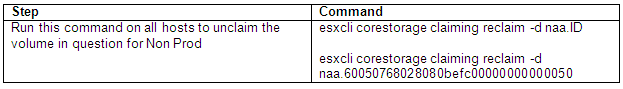
What is the VMware vSphere vMA?

The vSphere Management Assistant (vMA) is a SUSE Linux Enterprise Server 11‐based virtual machine that includes prepackaged software such as the vSphere command‐line interface, and the vSphere SDK for Perl.

Why use vMA?

  • vMA allows administrators to run scripts or agents that interact with ESXi hosts and vCenter Server systems without having to authenticate each time.
  • Used to remotely manage ESXi hosts
  • Central location to execute system management scripts

vMA Capabilities

  • vMA provides a flexible and authenticated platform for running scripts and programs.
  • As administrator, you can add vCenter Server systems and ESXi hosts as targets and run scripts and programs on these targets. Once you have authenticated while adding a target, you need not login again while running a vSphere CLI command or agent on any target.
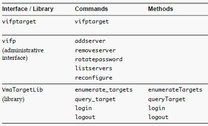
  • As a developer, you can use the APIs provided with the VmaTargetLib library to programmatically connect to vMA targets by using Perl or Java.
  • vMA enables reuse of service console scripts that are currently used for ESXi administration, though minor modifications to the scripts are usually necessary.
  • vMA comes preconfigured with two user accounts, namely, vi‐admin and vi‐user.
  • As vi‐admin, you can perform administrative operations such as addition and removal of targets. You can also run vSphere CLI commands and agents with administrative privileges on the added targets.
  • As vi‐user, you can run the vSphere CLI commands and agents with read‐only privileges on the target.
  • You can make vMA join an Active Directory domain and log in as an Active Directory user. When you run commands from such a user account, the appropriate privileges given to the user on the vCenter Server system or the ESXi host would be applicable.
  • vMA can run agent code that make proprietary hardware or software components compatible with VMware ESX. These code currently run in the service console of existing ESX hosts. You can modify most of these agent code to run in vMA, by calling the vSphere API, if necessary. Developers must move any agent code that directly interfaces with hardware into a provider.

vMA Component Overview

When you install vMA, you are licensed to use the virtual machine that includes all vMA components.

  • SUSE Linux Enterprise Server 11 SP1 – vMA runs SUSE Linux Enterprise Server on the virtual machine. You can move files between the ESXi host and the vMA console by using the vifs vSphere CLI command.
  • VMware Tools – Interface to the hypervisor.
  • vSphere CLI – Commands for managing vSphere from the command line. See the vSphere Command‐Line Interface Installation and Reference Guide.
  • vSphere SDK for Perl – Client‐side Perl framework that provides a scripting interface to the vSphere API. The SDK includes utility applications and samples for many common tasks.
  • Java JRE version 1.6 – Runtime engine for Java‐based applications built with vSphere Web Services SDK.
  • vi‐fastpass ‐ Authentication component.

Requirements

  • AMD Opteron, rev E or later
  • Intel processors with EM64T support with VT enabled.
  • vSphere 5.0
  • vSphere 4.1 or later
  • vSphere 4.0 Update 2 or later
  • vCenter Application 5.0

vSphere Authentication Mechanism

vMA’s authentication interface allows users and applications to authenticate with the target servers using vi‐fastpass or Active Directory. While adding a server as a target, the Administrator can determine if the target needs to use vi‐fastpass or Active Directory authentication. For vi‐fastpass authentication, the credentials that a user has on the vCenter Server system or ESXi host are stored in a local credential store. For Active Directory authentication, the user is authenticated with an Active Directory server.

When you add an ESXi host as a fastpass target server, vi‐fastpass creates two users with obfuscated passwords on the target server and stores the password information on vMA:

  • vi‐admin with administrator privileges
  • vi‐user with read‐only privileges

The creation of vi‐admin and vi‐user does not apply for Active Directory authentication targets. When you add a system as an Active Directory target, vMA does not store any information about the credentials. To use the Active Directory authentication, the administrator must configure vMA for Active Directory.

After adding a target server, you must initialize vi‐fastpass so that you do not have to authenticate each time you run vSphere CLI commands. If you run a vSphere CLI command without initializing vi‐fastpass, you will be asked for username and password. You can initialize vi‐fastpass by using one of the following methods:

  • Run vifptarget -s esx1.testdomain.local
  • Call the Login method in a Perl or Java program

Installing vMA

Download the vMA from the following location

https://my.vmware.com/web/vmware/details?productId=229&downloadGroup=VMA50

  • Use a vSphere Client to connect to a system that is running the supported version of ESXi or vCenter Server.
  • If connected to a vCenter Server system, select the host to which you want to deploy vMA in the inventory pane.
  • Select File > Deploy OVF Template. The Deploy OVF Template wizard appears.
  • Select Deploy from a file or URL if you have already downloaded and unzipped the vMA virtual appliance package.

VMA5

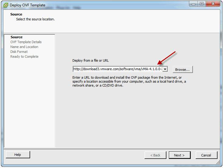
  • Click Browse, select the OVF, and click Next.

VMA6

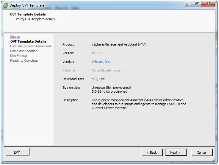
  • Click Next when the OVF template details are displayed.
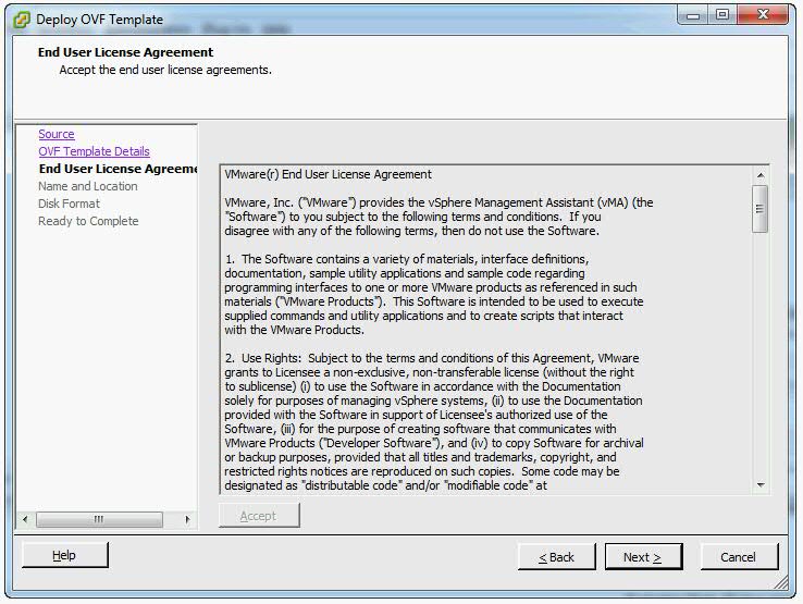
  • Accept the license agreement and click Next.

VMA7

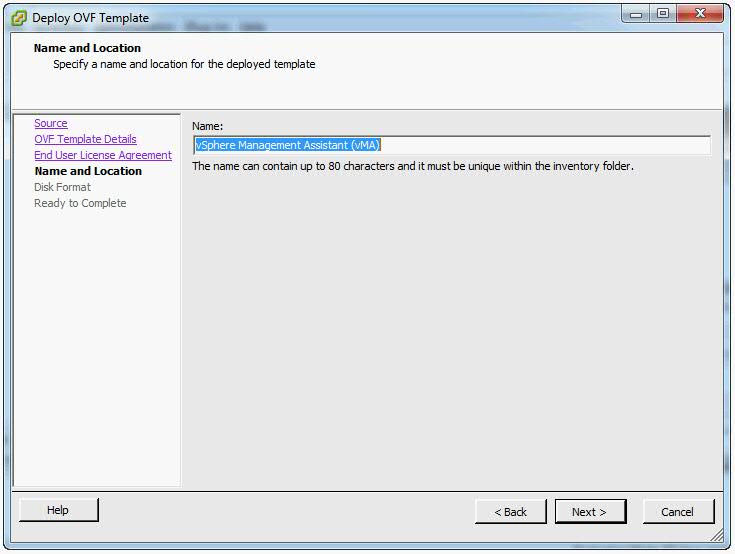
  • Specify a name for the virtual machine. You can also accept the default virtual machine name. Select an inventory location for the virtual machine when prompted. If you are connected to a vCenter Server system, you can select a folder.

VMA8

  • If connected to a vCenter Server system, select the resource pool for the virtual machine. By default, the top‐level root resource pool is selected.
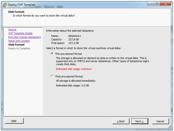
  • If prompted, select the datastore to store the virtual machine on and click Next.
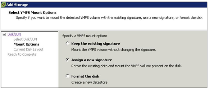
  • Select the required disk format option and click Next.

VMA9

  • Finish
  • IMPORTANT. Enure that vMA is connected to the management network on which the vCenter Server system and the ESXi hosts that are intended vMA targets are located.

vma10

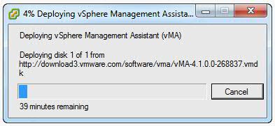
  • Review the information and click Finish.
  • The wizard deploys the vMA virtual machine to the host that you selected. The deploy process can take several minutes.
  • In the vSphere Client, right‐click the virtual machine, and click Power On.
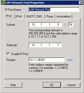
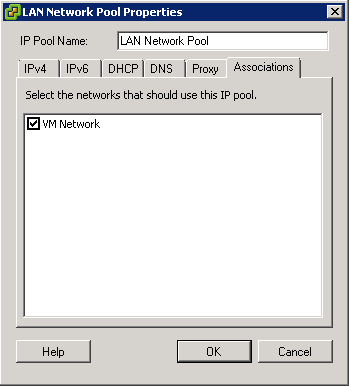
  • You may encounter a network IP Pool error message. If you do follow the link below and make sure you set up your IP pools like the example below
  • http://kb.vmware.com.Id=2007012

Capture

Capture2

  • Select the Console tab and answer the network configuration prompts
  • When prompted, specify a password for the vi‐admin user. You will first have to enter the old password which is vmware. The system will then only accept a strong password for the change
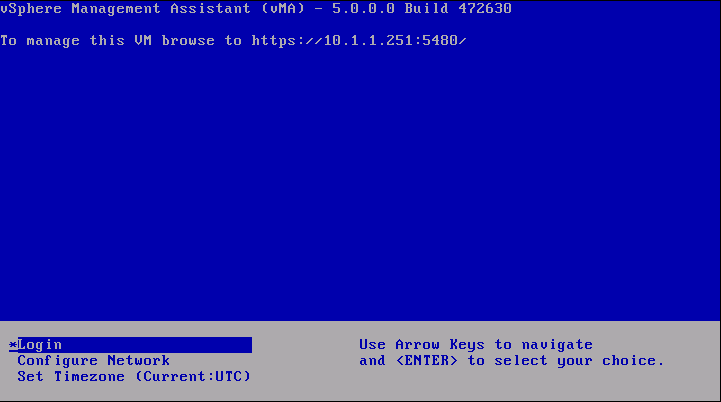
  • vMA is now configured and the vMA console appears. The console displays the URL from which you can access the Web UI.

Upgrading or Updating

Upgrading

IMPORTANT: You cannot upgrade a previous version of vMA to vMA 5.0. You must install a fresh vMA 5.0 instance.

Updating

You can download software updates including security fixes from VMware and components included in vMA, such as the SUSE Linux Enterprise Server updates and JRE.

  • Access the Web UI on Port 5480
  • Log in as vi‐admin.

vma

  • Click the Update tab and then the Status tab.
  • Open the Settings tab and then from the Update Repository section, select a repository.
  • Click Check Updates.
  • Click Install Updates.
  • You can also set an automatic download schedule for updates

Configure vMA for Active Directory Authentication

Configure vMA for Active Directory authentication so that ESXi hosts and vCenter Server systems added to Active Directory can be added to vMA without having to store the passwords in vMA’s credential store. This is a more secure way of adding targets to vMA.

  • Ensure that the DNS server configured for vMA is the same as the DNS server of the domain. You can change the DNS server by using the vMA Console or the Web UI
  • Ensure that the domain is accessible from vMA.
  • Ensure that you can ping the ESXi and vCenter server systems that you want to add to vMA and that pinging resolves the IP address to , where domainname is the domain to which vMA is to be added.
  • From the vMA console, run the following command
  •  sudo domainjoin-cli join dacmt.local administrator
  • When prompted, provide the Active Directory administratorʹs password.

vma-ad

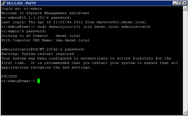
  • On successful authentication, the command adds vMA as a member of the domain. The command also adds entries in the /etc/hosts file with vmaHostname.domainname.
  • Restart vMA
  • Now, you can add an Active Directory target to vMA
  • Note: You can also access the Web UI

Add Target Servers to vMA

After you configure vMA, you can add target servers that run the supported vCenter Server or ESXi version. For vCenter Server, and ESXi system targets, you must have the name and password of a user who can connect to that system

To add a vCenter Server system as a vMA target for Active Directory Authentication

  • Log in to vMA as vi‐admin.
  • Add a server as a vMA target by running the following command

vifp addserver vc1.mycomp.com –authpolicy adauth –username ADDOMAIN\user1

Here, –authpolicy adauth indicates that the target needs to use the Active Directory authentication. If you run this command without the –username option, vMA prompts for the name of the user that can connect to the vCenter Server system. You can specify this user name as shown in the following example:

If –authpolicy is not specified in the command, then fpauth is taken as the default authentication policy.

  • Verify that the target server has been added by typing

vifp listservers –long

  • Set the target as the default for the current session:

vifptarget –set | -s

  • Verify that you can run a vSphere CLI command without authentication by running a command on one of the ESXi hosts, for example:

esxcli –server –vihost network nic list

  • The command runs without prompting for authentication information.

IMPORTANT: If the name of a target server changes, you must remove the target server by using vifp removeserver with the old name, then add the server using vifp addserver with the new name

vma2

To add a vCenter Server system as a vMA target for fastpass Authentication

  • Log in to vMA as vi‐admin
  • Add a server as a vMA target by running the following command:

vifp addserver vc2.mycomp.com –authpolicy fpauth

Here, –authpolicy fpauth indicates that the target needs to use the fastpass authentication.

  • Specify the username when prompted: MYDOMAIN\user1Specify the password for that user when prompted.
  • Review and accept the security risk information.
  • Verify that the target server has been added.

vifp listservers –long

  • Set the target as the default for the current session.

vifptarget –set | -s

  • Verify that you can run a vSphere CLI command without authentication by running a command on one of the ESXi hosts, for example:

esxcli –server –vihost network nic list

IMPORTANT: If the name of a target server changes, you must remove the target server by using vifp removeserver with the old name, then add the server using vifp addserver with the new name

To add an ESXi host as a vMA target

  • Log in to vMA as vi‐admin.
  • Run addserver to add a server as a vMA target.

vifp addserver Serverxyz

  • You are prompted for the target server’s root user password.Specify the root password for the ESXi host that you want to add.
  • vMA does not retain the root password. Instead, vMA adds vi‐admin and vi‐user to the ESXi host, and stores the obfuscated passwords that it generates for those users in the VMware credential store.

In a vSphere client connected to the target server, the Recent Tasks panel displays information about the users that vMA adds. The target server’s Users and Groups panel displays the users if you select it.

  • Verify that the target server has been added:

vifp listservers

  • Set the target as the default for the current session.

vifptarget –set | -s Serverxyz

  • Verify that you can run a vSphere CLI command without authentication by running a command, for example:

esxcli network nic list

Running vSphere CLI for the Targets

If you have added multiple target servers, by default, vMA executes commands on the first server that you added. You should specify the server explicitly when running commands.

To run vSphere CLI for the targets

  • Add servers as vMA targets.

vifp addserver vCenterserver
vifp addserver serverxyz

  • Verify that the target server has been added:

vifp listservers

  • Run vifptarget.

vifptarget -s serverxyz

  • The command initializes the specified target server. Now, this server will be taken as the default target forthe vSphere CLI or vSphere SDK for Perl scripts.
  • Run vSphere CLI or vSphere SDK for Perl scripts, by specifying the target server. For example:

esxcli –server serverxyz network nic list

Target Management Example Sequence

The following sequence of commands adds an ESXi host, lists servers, runs vifptarget to enable vi‐fastpass, runs a vSphere CLI command, and removes the ESXi host.

  • vifp addserver serverxyz.company.com
  • Type password: <password, not echoed to screen>
  • vifp listservers
  • serverxyz.company.com ESX
  • vifptarget –set serverxyz.company.com
  • esxcli storage core path list

cdrom vmhba0:1:0 (0MB has 1 paths and policy of fixed
Local 0:7:1 vmhba0:1:0 On active preferred

  • vifp removeserver server1.company.com
  • <password, not echoed to screen>

Enable the vi-user for the first time

  • Log into vMA as vi-admin
  • Set a password for the vi-user account
  • sudo passwd vi-user

Note: The vi-admin is not “root” and receives all its privileges from the configuration of sudo. Sudo is a delegation system that allows “root” to allow other users privileges above and beyond merely being a “user.”

Adding another user alongside vi-admin and vi-user

‘sudo useradd username -p password’

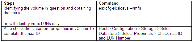
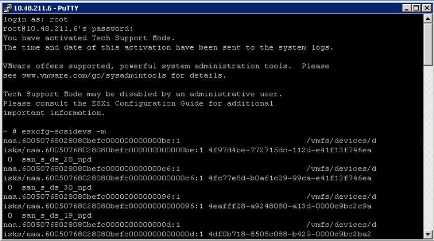
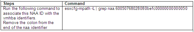
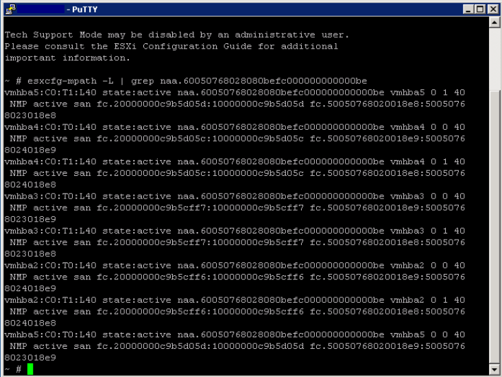
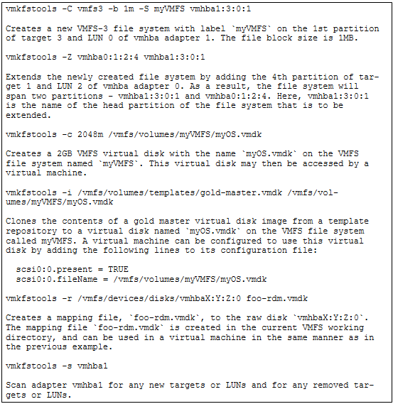
Use vmkfstools to manage VMFS Datastores

Useful Command Ref

http://vmetc.com/wp-content/uploads/2007/11/man-vmkfstools.txt

vmkfstools

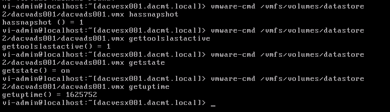
Use vmware-cmd to manage VMs

Useful Command Ref

http://www.vmware.com/support/developer/vcli/vcli41/doc/reference/vmware-cmd.html

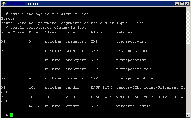
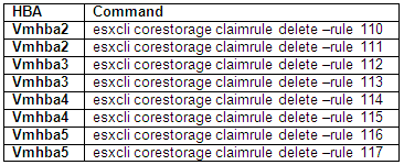
Example showing 4 different commands

vmware-cmd

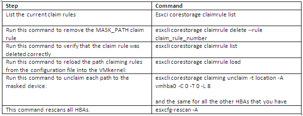
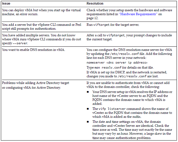
Troubleshoot common vMA errors and conditions

vma

VMware TV

http://www.youtube.com/watch?v=cIh4QT0-hdY

Changing the IP Address or Hostname of vMA

https://communities.vmware.com/people/ravinder1982/blog/2012/06/15/changing-ip-address-or-hostname-of-vma