Archive for March 2012

UEFI

UEFI = Unified Extensible Firmware Interface

After more than 30 years of unerring and yet surprising supremacy, BIOS — the IBM PC’s Basic Input Output System will be taking a backseat to UEFI. a specification that begun its life as the Intel Boot Initiative way back in 1998 when BIOS’s antiquated limitations were hampering systems built with Intel’s Itanium processors. Later, the Initiative became EFI, and in 2005 Intel donated EFI to the newly-formed UEFI Forum, a consortium made up of the usual suspects: AMD, Apple, IBM, Intel, Microsoft, and so on.

UEFI, or Unified Extensible Firmware Interface, is a complete re-imagining of a computer boot environment, and as such it has almost no similarities to the PC BIOS that it replaces. While BIOS is fundamentally a solid piece of firmware, UEFI is a programmable software interface that sits on top a computer’s hardware and firmware (and indeed UEFI can and does sit on top of BIOS). Rather than all of the boot code being stored in the motherboard’s BIOS, UEFI sits in the/EFI/ directory in some non-volatile memory; either in NAND on the motherboard, on your hard drive, or on a network share

As a result, UEFI almost resembles a light-weight operating system. A computer boots into UEFI, an arbitrary set of actions are carried out, and then it triggers the loading of an operating system. Further reinforcing its OSness, the UEFI spec defines boot and runtime services, protocols for communication between services, device drivers (UEFI is designed to work across all platforms), extensions, and even an EFI shell, where you can run EFI applications. On top of all this is the boot loader, which executes an operating system’s boot loader.

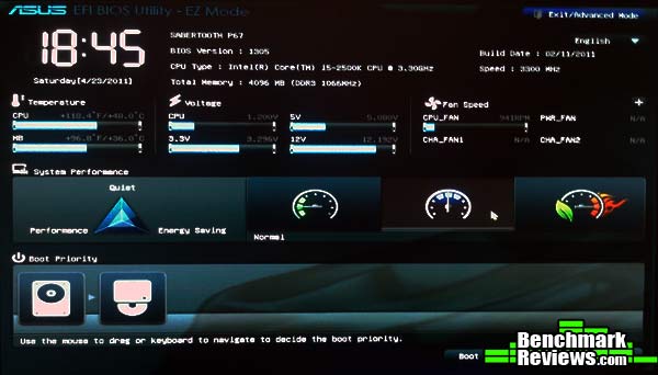
UEFI, being a pseudo-operating system, can access all of the hardware on the computer, you can surf the internet from the UEFI interface, or backup your hard drives, and it even has a full, mouse-driven GUI (below right). The fact that all of this boot data is stored on NAND flash or on a hard drive means that there’s a lot more space for things like language localization, boot-time diagnostics and utilities (backup, restore, malware scanners)

UEFI is still very young, and very few operating systems actually take advantage of any of the features listed above. Linux certainly supports UEFI, but doesn’t really utilizes it. Mac OS X makes slightly better use of UEFI with the Bootcamp boot manager. Windows 8, when it launches in 2012, will probably be the first major OS to take extensive advantage of UEFI, with Restore, Refresh, secure boot, and possibly more.

VMware vSphere 5 supports booting ESXi hosts from the UEFI. UEFI allows you to boot systems from USB Media (as well as hard drives and CD-ROM Drives)

VMware RDMs

What is RAW Device Mapping?

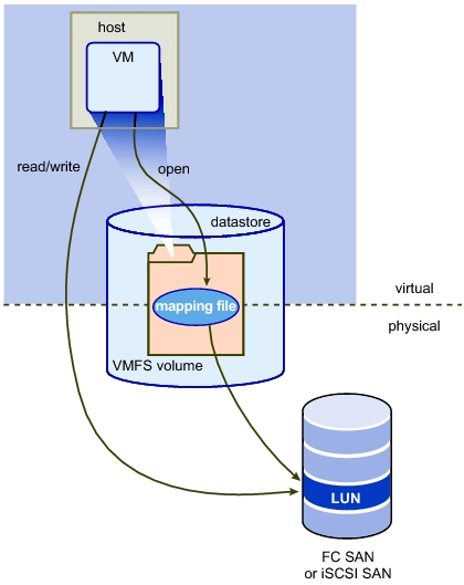
A Raw Device Mapping allows a special file in a VMFS volume to act as a proxy for a raw device. The mapping file contains metadata used to manage and redirect disk accesses to the physical device. The mapping file gives you some of the advantages of a virtual disk in the VMFS file system, while keeping some advantages of direct access to physical device characteristics. In effect it merges VMFS manageability with raw device access

A raw device mapping is effectively a symbolic link from a VMFS to a raw LUN. This makes LUNs appear as files in a VMFS volume. The mapping file, not the raw LUN is referenced in the virtual machine configuration. The mapping file contains a reference to the raw LUN.

Note that raw device mapping requires the mapped device to be a whole LUN; mapping to a partition only is not supported.

Uses for RDM’s

  • Use RDMs when VMFS virtual disk would become too large to effectively manage.

For example, When a VM needs a partition that is greater than the VMFS 2 TB limit is a reason to use an RDM. Large file servers, if you choose to encapsulate them as a VM, are a prime example. Perhaps a data warehouse application would be another. Alongside this, the time it would take to move a vmdk larger than this would be significant.

  • Use RDMs to leverage native SAN tools

SAN snapshots, direct backups, performance monitoring, and SAN management are all possible reasons to consider RDMs. Native SAN tools can snapshot the LUN and move the data about at a much quicker rate.

  • Use RDMs for virtualized MSCS Clusters

Actually, this is not a choice. Microsoft Clustering Services (MSCS) running on VMware VI require RDMs. Clustering VMs across ESX hosts is still commonly used when consolidating hardware to VI. VMware now recommends that cluster data and quorum disks be configured as raw device mappings rather than as files on shared VMFS

Terminology

The following terms are used in this document or related documentation:

  • Raw Disk — A disk volume accessed by a virtual machine as an alternative to a virtual disk file; it may or may not be accessed via a mapping file.
  • Raw Device — Any SCSI device accessed via a mapping file. For ESX Server 2.5, only disk devices are supported.
  • Raw LUN — A logical disk volume located in a SAN.
  • LUN — Acronym for a logical unit number.
  • Mapping File — A VMFS file containing metadata used to map and manage a raw device.
  • Mapping — An abbreviated term for a raw device mapping.
  • Mapped Device — A raw device managed by a mapping file.
  • Metadata File — A mapping file.
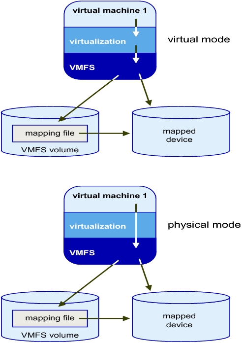
  • Compatibility Mode — The virtualization type used for SCSI device access (physical or virtual).
  • SAN — Acronym for a storage area network.
  • VMFS — A high-performance file system used by VMware ESX Server.

Compatibility Modes

Physical Mode RDMs

  • Useful if you are using SAN-aware applications in the virtual machine
  • Useful to run SCSI target based software
  • Physical mode is useful to run SAN management agents or other SCSI target based software in the virtual machine
  • Physical mode for the RDM specifies minimal SCSI virtualization of the mapped device, allowing the greatest flexibility for SAN management software. In physical mode, the VMkernel passes all SCSI commands to the device, with one exception: the REPORT LUNs command is virtualized, so that the VMkernel can isolate the LUN for the owning virtual machine. Otherwise, all physical characteristics of the underlying hardware are exposed.

Virtual Mode RDMs

  • Advanced file locking for data protection
  • VMware Snapshots
  • Allows for cloning
  • Redo logs for streamlining development processes
  • More portable across storage hardware, presenting the same behavior as a virtual disk file

Setting up RDMs

  •  Right click on the Virtual Machine and select Edit Settings
  • Under the Hardware Tab, click Add
  • Select Hard Disk
  • Click Next
  • Click Raw Device Mapping

If the option is greyed out, please check the following.

http://kb.vmware.com/RDM Greyed Out

  • From the list of SAN disks or LUNs, select a raw LUN for your virtual machine to access directly.
  • Select a datastore for the RDM mapping file. You can place the RDM file on the same datastore where your virtual machine configuration file resides,
    or select a different datastore.
  • Select a compatibility mode. Physical or Virtual
  • Select a virtual device node
  • Click Next.
  • In the Ready to Complete New Virtual Machine page, review your selections.
  • Click Finish to complete your virtual machine.

Note: To use vMotion for virtual machines with enabled NPIV, make sure that the RDM files of the virtual machines are located on the same datastore. You cannot perform Storage vMotion or vMotion between datastores when NPIV is enabled.

NUMA

Intro

For the past decade, processor clock speed has skyrocketed at rates exceeding even the predictions of Moores Law. A multi Gigahertz CPU, however needs to be supplied with an enormous amount of memory bandwidth in order to do its processing effectively.

Even a single CPU running a memory intensive workload such as a scientific computing application, can find itself constrained by memory bandwidth

These problems are amplified many times over on symmetric multiprocessing (SMP) systems where many processors must compete for bandwidth on the same system bus.

What is NUMA?

NUMA is Non Uniform Memory Access

NUMA is an alternative approach that links several small, cost-effective nodes via a high performance interconnect. Each node contains both processors and memory, much like a small SMP system. However, an advanced memory controller allows a node to use memory on all other nodes, creating a single system image. When a processor accesses memory that does not lie within its own node (remote memory), the data must be transferred over the NUMA interconnect, which is slower than accessing local memory. Thus, memory access times are “non-uniform,” depending on the location of the memory, as the technology’s name implies

So what does Non-Uniform Memory Access really mean?

Non-Uniform Memory Access means that it will take longer to access some regions of memory than others. This is due to the fact that some regions of memory are on physically different busses from other regions

Imagine that you are baking a cake. You have a group of ingredients (=memory pages) that you need to complete the recipe(=process). Some of the ingredients you may have in your cabinet(=local memory), but some of the ingredients you might not have, and have to ask a neighbor for(=remote memory). The general idea is to try and have as many of the ingredients in your own cabinet as possible, since this reduces your time and effort in making the cake.
You also have to remember that your cabinets can only hold a fixed amount of ingredients(=physical nodal memory). If you try and buy more, but you have no room to store it, you may have to ask your neighbor to keep it in his/her cabinet until you need it(=local memory full, so allocate pages remotely).

What is meant by Local and Remote Memory?

The terms local memory and remote memory are typically used in reference to a currently running process. That said, local memory is typically defined to be the memory that is on the same node as the CPU currently running the process. Any memory that does not belong to the node on which the process is currently running is then, by that definition, remote.
Local and remote memory can also be used in reference to things other than the currently running process. When in interrupt context, there technically is no currently executing process, but memory on the node containing the CPU handling the interrupt is still called local memory. Also, you could use local and remote memory in terms of a disk. For example if there was a disk (attatched to node 1) doing a DMA, the memory it is reading or writing would be called remote if it were located on another node (ie: node 0)

What is the difference between NUMA and SMP?

The NUMA architecture was designed to surpass the scalability limits of the SMP architecture. With SMP, which stands for Symmetric Multi-Processing, all memory access are posted to the same shared memory bus. This works fine for a relatively small number of CPUs, but the problem with the shared bus appears when you have dozens, even hundreds, of CPUs competing for access to the shared memory bus. NUMA alleviates these bottlenecks by limiting the number of CPUs on any one memory bus, and connecting the various nodes by means of a high speed interconnect.

Why should I use NUMA? What are the benefits of NUMA?

The main benefit of NUMA is, as mentioned above, scalability. It is extremely difficult to scale SMP past 8-12 CPUs. At that number of CPUs, the memory bus is under heavy contention. NUMA is one way of reducing the number of CPUs competing for access to a shared memory bus. This is accomplished by having several memory busses and only having a small number of CPUs on each of those busses. There are other ways of building massively multiprocessor machines

Issues

The high latency of remote memory accesses can leave the processors under-utilized, constantly waiting for data to be transferred to the local node and the NUMA interconnect can also become a bottleneck for applications with high memory bandwidth demands.

Furthermore, performance on such a system may be highly variable, for example, if an application has memory located  locally on one benchmarking run, but a subsequent run happens to place all that memory on a remote node. This phenomenon can make capacity planning much more difficult. Finally processor clocks may not be synchronised between multiple nodes so applications that read this clock directly may be behave incorrectly.

Typical Four-Processor NUMA Node Architecture

High-end servers are designed to support more than one system bus. One design approach is to create a number of nodes where each node contains some processors, some memory, and, in some cases, an I/O subsystem as per below pic


Two Four-Processor NUMA Nodes Connected as an Eight-Processor NUMA System

To increase system capacity, additional nodes are connected using the high-speed cache-coherent system interconnect, as shown
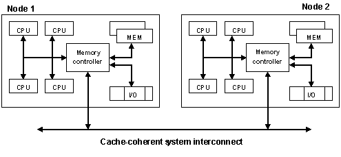
In the diagram, all eight processors can access memory in both nodes coherently. For example:

  • A processor in Node 1 can access memory within Node 1, (that is, local or “near” memory) using a direct path through the memory controller in Node 1.
  • For the same processor to access memory in Node 2 (that is, “remote” or “far” memory), the path taken is through the memory controller in Node 1, out through the system interconnect, and then through the memory controller in Node 2.

It takes more time to access memory in another node than it takes to access local memory. This difference in memory access times is the origin of the name for these systems: non-uniform memory architecture (NUMA).

The ratio of the time taken to access near memory to the time taken to access far memory is referred to as the NUMA ratio. The higher the NUMA ratio value — that is, the greater the disparity between the time it takes to access far memory as compared to near memory — the greater the effect that NUMA characteristics may have on software performance.

3:1 being an optimal ratio