Archive for February 2012

Changing vCenters IP Address

The Challenge

Currently at my work, our network team have decided they want to create a new VMware Management VLAN (Headache Time) They want us to move vCenter on to this new VLAN and assign a new…

  1. IP Address
  2. Subnet Mask
  3. Gateway
  4. VMware Port Group VLAN ID

So what can possibly go wrong?…. Apparently quite a lot

Once the networking is changed on your vCenter, the ESX(i) hosts disconnect because they store the IP address of the vCenter Server in configuration files on each of the individual servers. This incorrect address continues to be used for heartbeat packets to vCenter Server.

You may also experience connectivity issues with vSphere Update Manager, Autodeploy, Syslog and Dump Collector.

Things to remember

  1. Ensure you have a vCenter database backup.
  2. Once the vCenter IP address has changed all that should be necessary is to reconnect the hosts back into vCenter.
  3. Please ensure that the vCenter DNS entry gets updated with the correct IP address. In addition ensure you have intervlan routing configured correctly.
  4. In the worst case scenario and you have to recreate the vCenter database then all you will lose is historic performance data and resource pools.
  5. You will need to change the Port Group VLAN
  6. Creating a second nic on the vCenter and assigning it the IP address of the new VLAN won’t be of assistance as you will need to select a managed vCenter IP address if you do this

How to resolve this

There are two methods to get the ESX hosts connected again. Try each one in order

Method 1
  1. Log in as root to the ESX host with an SSH client.
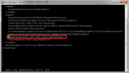
  2. Using a text editor, edit the /etc/opt/vmware/vpxa/vpxa.cfg file and change the parameter to the new IP of the vCenter Server.
  3. Or for ESXi 4 and 5, navigate to the folder /etc/vmware/vpxa and with vi open the file: vpxa.cfg. Search for the line that starts with: and then change this parameter to the new IP address of the vCenter Server.
  4. Save your changes and exit.
  5. Restart the management agents on the ESX.
  6. Restart the VirtualCenter Server service with this command: # services.sh
  7. Return to the vCenter Server and restart the “VMware VirtualCenter Server” Service.

Note: This procedure can be performed on an ESXi host through Tech Support mode with the help of a VMware Technical Support Engineer.

Method 2
  1. From vSphere Client, right-click the ESX host and click Disconnect.
  2. From vSphere Client, right-click the ESX host and click Reconnect. If the IP is still not correct, go to step 3.
  3. From vSphere Client, right-click the ESX host and click Remove.
  4. Caution: After removing the host from vCenter Server, all the performance data for the virtual machines and the performance data for the host will be lost
  5. Reinstall the VMware vCenter Server agent.
  6. Select New > Add Host.
  7. Enter the information used for connecting to the host

Firewall/Router Passthrough

If the IP traffic between the vCenter Server and ESX host is passing through a NAT device like a firewall or router and the vCenter Server’s IP is translated to an external or WAN IP, update the Managed IP address:
  1. From vSphere Client connected to the vCenter Server top menu, click Administration and choose VirtualCenter Management Server Configuration.
  2. Click Runtime Settings from the left panel.
  3. Change the vCenter Server Managed IP address.
  4. If the DNS name of the vCenter Server has changed, update the vCenter Server Name field with the new DNS name

How we changed IP Address step by step on vSphere 4.1

  • First of all Remote Desktop into your vCenter Server and change the IP Address, Subnet Mask and Gateway.
  • Make sure inter vlan routing is configured between your new subnet and the subnet your DNS servers are on if this is the case
  • Go to your DNS Server and delete the entry for your current vcenter server
  • Add the new A Record for your vCenter Server
  • You may need to run an ipconfig /flushdns on the systems you are working on.
  • Try reconnecting via Remote Desktop to your vCenter Server to establish connectivity
  • Click Home and go to vCenter Server Settings and adjust vCenter’s IP address
  • At this point, all your hosts will have disconnected? (Don’t panic!)
  • At this point we logged into the host which runs vCenter using the vClient and changed the VLAN on the port group vCenter was on.
  • Go back to your logon into vCenter
  • Right click on the first disconnected hosts and click Connect
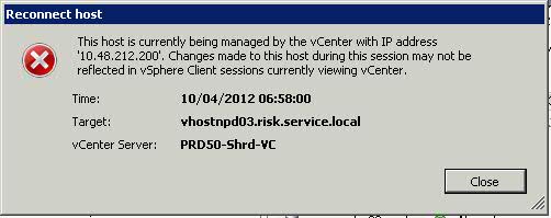
  • The below error message will appear

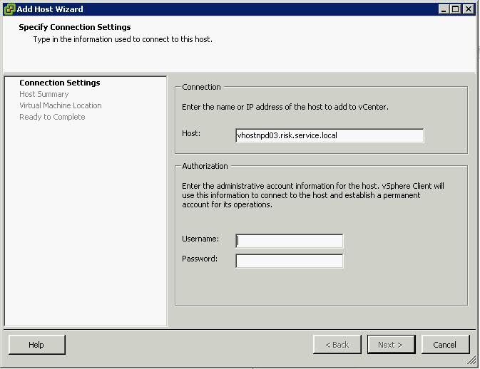
  • Click Close and then an Add host box will appear as per below screenprint

  • The host should now connect back in and adjust for HA

If you get any error messages afterwards then the IP Addres will need to be updated in a couple of other places. See link below
http://kb.vmware.com/selfservice/microsites/search.do?language=en_US&cmd=displayKC&externalId=1014213


IP Addressing and Subnet Masks

This comes up again and again and I wanted to write a post which tries to simplify this as much as possible as it’s continually been a useful skill to have as well as a reference when out and about if needed 🙂

An IP (Internet Protocol) address is a unique identifier for a node or host connection on an IP network. An IP address is a 32 bit binary number usually represented as 4 decimal values, each representing 8 bits, in the range 0 to 255 (known as octets) separated by decimal points. This is known as “dotted decimal” notation

Address classes

Class Description Binary Decimal No of Networks Number of addresses
A Universal Unicast 0xxx 1-126 27 = 128 224 = 16777216
B Universal Unicast 10xx 128-191 214 = 16384 216 = 65536
C Universal Unicast 110x 192-223 221 = 2097152 28 = 256
D Multicast 1110 224-239 tbc tbc
E Not used 1111 240-254 tbc tbc

Example

X is the network address and n is the node address on that network

Class Network and Node Address
A XXXXXXXX.nnnnnnnn.nnnnnnnn.nnnnnnnn
B XXXXXXXX.XXXXXXXX.nnnnnnnn.nnnnnnnn
C XXXXXXXX.XXXXXXXX.XXXXXXXX.nnnnnnnn

Private IP Addresses

These are non routable on the internet and are assigned as internal IP Addresses within a company/Private network

Address Range Subnet Mask
10.0.0.0 – 10.255.255.255 255.0.0.0
172.16.0.0 – 172.31.255.255 255.240.0.0
192.168.0.0 to 192.168.255.255 255.255.0.0

APIPA

APIPA is a DHCP failover mechanism for local networks. With APIPA, DHCP clients can obtain IP addresses when DHCP servers are non-functional. APIPA exists in all modern versions of Windows except Windows NT.

When a DHCP server fails, APIPA allocates IP addresses in the private range

169.254.0.1 to 169.254.255.254.

Clients verify their address is unique on the network using ARP. When the DHCP server is again able to service requests, clients update their addresses automatically.

Binary Finary

A major stumbling block to successful subnetting is often a lack of understanding of the underlying binary math. IP Addressing is based on the Power of 2 binary maths as seen below

x 2x 2x
0 20 1
1 21 2
2 22 4
3 23 8
4 24 16
5 25 32
6 26 64
7 27 128

An IP Address actually looks like the below when you write it out

10001100. 10110011.11011100.11001000

140 179 220 200
10001100 10110011 11011100 11001000

Each numerical value for the 8 1’s and 0’s can be seen in the table below. You have to add together each value in the top column where it is 1 in the octet to reach the binary address number.

So for E.g 140 above in the first octet

128 + 8+ 4 = 140

128 64 32 16 8 4 2 1
1 0 0 0 1 1 0 0

Subnet Masks

Subnetting an IP Network can be done for a variety of reasons, including organization, use of different physical media (such as Ethernet, FDDI, WAN, etc.), preservation of address space, and security. The most common reason is to control network traffic. In an Ethernet network, all nodes on a segment see all the packets transmitted by all the other nodes on that segment. Performance can be adversely affected under heavy traffic loads, due to collisions and the resulting retransmissions. A router is used to connect IP networks to minimize the amount of traffic each segment must receive

Applying a subnet mask to an IP address allows you to identify the network and node parts of the address. The network bits are represented by the 1s in the mask, and the node bits are represented by the 0s.

Default Subnet Masks

Class Address Binary Address
Class A 255.0.0.0 11111111.00000000.00000000.00000000
Class B 255.255.0.0 11111111.11111111.00000000.00000000
Class C 255.255.255.0 11111111.11111111.11111111.00000000

Performing a bitwise logical AND operation between the IP address and the subnet mask results in the Network Address or Number.

For example, using our test IP address and the default Class B subnet mask and doing the AND operation, we get

IP Address 10001100.10110011.11110000.11001000 140.179.220.200
Subnet Mask 11111111.11111111.00000000.00000000 255.255.0.0
Network Address 10001100.10110011.00000000.00000000      140.179.0.0

If both operands have nonzero values, the result has the value 1. Otherwise, the result has the value 0 so if both the IP Address and the subnet Mask have 1’s in the same part of the octet, the result is a 1. Convert to binary to find your network address.

Subnetting

In order to subnet a network, extend the natural mask using some of the bits from the host ID portion of the address to create a subnetwork ID. See the Submask row below in red

In this example we want to extend network address 204.17.5.0

IP Address 11001100.00010001.00000101.11001000 204.17.5.200
Subnet Mask 11111111.11111111.11111111.11100000 255.255.255.224
Network Address 11001100.00010001.00000101.00000000      204.17.5.0
Broadcast Address 11001100.00010001.00000101.11111111 204.17.5.255

In this example a 3 bit subnet mask was used. There are 8 (23)- 2 subnets available with this size mask however there are 2 taken for the network ID and Broadcast ID reserved addresses so 6 available subnets

The amount of bits left = 5 therefore the amount of usable addresses on this is (25)- 2 nodes = 30. (Remember that addresses with all 0’s and all 1’s are not allowed hence the -2).

So, with this in mind, these subnets have been created

Subnet addresses Host Addresses
204.17.5.0 / 255.255.255.224 1-30
204.17.5.32 / 255.255.255.224 33-62
204.17.5.64 / 255.255.255.224 65-94
204.17.5.96 / 255.255.255.224 97-126
204.17.5.128 / 255.255.255.224  129-158
204.17.5.160 / 255.255.255.224 161-190
204.17.5.192 / 255.255.255.224 193-222
204.17.5.224 / 255.255.255.224 225-254

CIDR Notation

Subnet Masks can also be described as slash notation as per below

Prefix Length in Slash Notation Equivalent Subnet Mask
/1 128.0.0.0
/2 192.0.0.0
/3 224.0.0.0
/4 240.0.0.0
/5 248.0.0.0
/6 252.0.0.0
/7 254.0.0.0
/8 255.0.0.0
/9 255.128.0.0
/10 255.292.0.0
/11 255.224.0.0
/12 255.240.0.0
/13 255.248.0.0
/14 255.252.0.0
/15 255.254.0.0
/16 255.255.0.0
/17 255.255.128.0
/18 255.255.192.0
/19 255.255.224.0
/20 255.255.240.0
/21 255.255.248.0.0
/22 255.255.252.0
/23 255.255.254.0
/24 255.255.255.0
/25 255.255.255.128
/26 255.255.255.192
/27 255.255.255.224
/28 255.255.255.240
/29 255.255.255.248
/30 255.255.255.252

Subnetting Tricks

1. How to work out your subnet range

Lets say you have a subnet Mask 255.255.255.240 (/28)

You need to do 256-240 = 16

Then your subnets are 0, 16, 32, 48, 64, 80, 96, 112, 128, 144, 160, 176, 192, 208, 224, 240

For the subnetwork 208 – 223 is the broadcast and 209-222 are the useable addresses on that subnet.

VMware “Host Mem MB” and “Guest Mem MB”

If you click on the cluster, then the virtual machines tab or on any virtual machine you will see a row of tabs with details on about performance. The below 3 give very accurate memory statistics which can help with future planning or even seeing where a performance problem lies

Memory Size -MB

The amount of memory given by an admin to the machine initially on build

Host Mem – MB

The metrics here is showing you how much memory a particular VM is consuming from the ESX(i) host that it’s being hosted on

Guest Mem – %

This is just a metric to show you how much of that memory is actually being actively used from the overall allocated memory.

VMware Memory Resource Management Doc

Understanding Memory Resource Management in VMware® ESX™ Server

Further explanation

What tends to confuse people is a rather high consumed host memory versus a low active guest memory … usually followed by the question on how exactly active guest memory is calculated.

1) Why is consumed host memory usage higher than active guest memory? (p.5)

“The hypervisor knows when to allocate host physical memory for a virtual machine because the first memory access from the virtual machine to a host physical memory will cause a page fault that can be easily captured by the hypervisor. However, it is difficult for the hypervisor to know when to free host physical memory upon virtual machine memory deallocation because the guest operating system free list is generally not publicly accessible. Hence, the hypervisor cannot easily find out the location of the free list and monitor its changes.”

So the host allocates memory pages upon their first request from the guest (that’s why consumed is less than the configured maximum), but doesn’t deallocate them once they are freed in the guest OS (because the host simply doesn’t see those guest deallocations). If the guest OS re-uses such previously allocated pages, the host won’t allocate more host memory. If the guest OS however allocates different pages, the host will also allocate more memory (up to the point where all configured memory pages for the specific guest have been allocated).

2) How is active guest memory calculated? (p.12)

“At the beginning of each sampling period, the hypervisor intentionally invalidates several randomly selected guest physical pages and starts to monitor the guest accesses to them. At the end of the sampling period, the fraction of actively used memory can be estimated as the fraction of the invalidated pages that are re-accessed by the guest during the epoch”.

DRS

What is DRS?

A DRS cluster is a collection of ESXi hosts and associated virtual machines with shared resources and a shared interface. Before you can obtain the benefits of cluster-level resource management you must create a DRS cluster.
When you add a host to a DRS cluster, the host’s resources become part of the cluster’s resources. In addition to this aggregation of resources, with a DRS cluster you can support cluster-wide resource pools and enforce cluster-level resource allocation policies. The following cluster-level resource management capabilities are also available.

DRS must use Shared Storage and a vMotion network

  • Load Balancing

The distribution and usage of CPU and memory resources for all hosts and virtual machines in the cluster are continuously monitored. DRS compares these metrics to an ideal resource utilization given the attributes of the cluster’s resource pools and virtual machines, the current demand, and the imbalance target. It then performs (or recommends) virtual machine migrations accordingly. When you first power on a virtual machine in the cluster, DRS attempts to maintain proper load balancing by either placing the virtual machine on an appropriate host or making a recommendation.

  • Power management

When the vSphere Distributed Power Management (DPM) feature is enabled, DRS compares cluster- and host-level capacity to the demands of the cluster’s virtual machines, including recent historical demand. It places (or recommends placing) hosts in standby power mode if sufficient excess capacity is found or powering on hosts if capacity is needed. Depending on the resulting host power state recommendations, virtual machines might need to be migrated to and from the hosts as well.

  • Affinity Rules

You can control the placement of virtual machines on hosts within a cluster, by
assigning affinity rules.

DRS, EVC and FT

Depending on whether or not Enhanced vMotion Compatibility (EVC) is enabled, DRS behaves differently when you use vSphere Fault Tolerance (vSphere FT) virtual machines in your cluster.

DRS

Migration Recommendations

The system supplies as many recommendations as necessary to enforce rules and balance the resources of the cluster. Each recommendation includes the virtual machine to be moved, current (source) host and destination host, and a reason for the recommendation. The reason can be one of the following:

  • Balance average CPU loads or reservations
  • Balance average memory loads or reservations
  • Satisfy resource pool reservations
  • Satisfy an affinity rule.
  • Host is entering maintenance mode or standby mode.

Note: If you are using the vSphere Distributed Power Management (DPM) feature, in addition to migration recommendations, DRS provides host power state recommendations

Using DRS Affinity Rules

You can control the placement of virtual machines on hosts within a cluster by using affinity rules. You can create two types of rules.

  • VM-Host

Used to specify affinity or anti-affinity between a group of virtual machines and a group of hosts. An affinity rule specifies that the members of a selected virtual machine DRS group can or must run on the members of a specific host DRS group. An anti-affinity rule specifies that the members of a selected virtual machine DRS group cannot run on the members of a specific host DRS group.

  • VM-VM

Used to specify affinity or anti-affinity between individual virtual machines. A rule specifying affinity causes DRS to try to keep the specified virtual machines together on the same host, for example, for performance reasons. With an anti-affinity rule, DRS tries to keep the specified virtual machines apart, for example, so that when a problem occurs with one host, you do not lose both virtual machines. When you add or edit an affinity rule, and the cluster’s current state is in violation of the rule, the system continues to operate and tries to correct the violation. For manual and partially automated DRS clusters, migration recommendations based on rule fulfillment and load balancing are presented for approval. You are not required to fulfill the rules, but the corresponding recommendations remain until the rules are fulfilled.

To check whether any enabled affinity rules are being violated and cannot be corrected by DRS, select the cluster’s DRS tab and click Faults. Any rule currently being violated has a corresponding fault on this page.
Read the fault to determine why DRS is not able to satisfy the particular rule. Rules violations also produce a log event.

DRS Automation Levels

Someone at my work asked me about these levels and wanted an explanation for the Aggressive Level. He said he envisaged machines continually moving around in a state of perpetual motion. Lets find out!

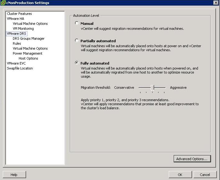
Just as a note, you access DRS Automation Level Settings by right clicking on the cluster and selecting Edit Settings, then selecting VMware DRS

There are 3 settings

  1. Manual – vCenter will suggest migration recommendations for virtual machines
  2. Partially Automated – Virtual machines will be placed onto hosts at power on and vCenter will suggest migration recommendations for virtual machines
  3. Fully Automated – Virtual machines will be automatically places on to hosts when powered on and will be automatically migrated from one host to another to optimize resource usage

For Fully Automated there is a slider called Migration threshold

You can move the slider to use one of the five levels

  • Level 1 – Apply only five-star recommendations. Includes recommendations that must be followed to satisfy cluster constraints, such as affinity rules and host maintenance. This level indicates a mandatory move, required to satisfy an affinity rule or evacuate a host that is entering maintenance mode.
  • Level 2 – Apply recommendations with four or more stars. Includes Level 1 plus recommendations that promise a significant improvement in the cluster’s load balance.
  • Level 3 – Apply recommendations with three or more stars. Includes Level 1 and 2 plus recommendations that promise a good improvement in the cluster’s load balance.
  • Level 4 – Apply recommendations with two or more stars. Includes Level 1-3 plus recommendations that promise a moderate improvement in the cluster’s load balance.
  • Level 5 – Apply all recommendations. Includes Level 1-4 plus recommendations that promise a slight improvement in the cluster’s load balance.

Some interesting facts

  • DRS has a threshold of up to 60 vMotion events per hour
  • It will check for imbalances in the cluster once every five minutes

vCenter Console

DRS

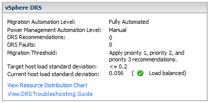
When the Current host load standard deviation exceeds the target host load standard deviation, DRS will make recommendations and take action based on the automation level and migration threshold

The target host load standard deviation is derived from the migration threshold setting. A load is considered imbalanced as long as the current value exceeds the migration threshold.

Each host has a host load metric based upon the CPU and memory resources in use. It is described as the sum of expected virtual machine loads divided by the capacity of the host. The LoadImbalanceMetric also known as the current host load standard deviation is the standard deviation (average of averages) of all host load metrics in a cluster.

DRS decides what virtual machines are migrated based on simulating a move and recalculating the current host load standard deviation and making a recommendation. As part of this simulation, a cost benefit and risk analysis is performed to determine best placement. DRS will continue to perform simulations and will make recommendations as long as the current host load exceeds the target host load.

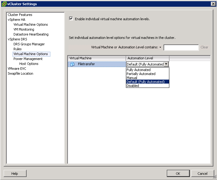
Properly size virtual machine automation levels based on Application Requirements

  • When a virtual machine is powered on, DRS is responsible for performing initial placement. During initial placement, DRS considers the “worst case scenario” for a VM. For example, when a new server that has been overspec’d gets powered on, DRS will actively attempt to identify a host that can guarantee that CPU and RAM to the VM. This is due to the fact that historical resource utilization statistics for the VM are unavailable. If DRS cannot find a cluster host able to accommodate the VM, it will be forced to “defragment” the cluster by moving other VMs around to account for the one being powered on. As such, VMs should be be sized based on their current workload.
  • When performing an assessment of a physical environment as part of a vSphere migration, an administrator should leverage the resource utilization data from VMware Capacity Planner in allocating resources to VMs.
  • Do not set VM reservations too high as this can affect DRS Balancing DRS might not have excess resources to move VMs around
  • Group Virtual Machines for a multi-tier service into a Resource Pool
  • Don’t forget to calculate memory overhead when sizing VMs into clusters
  • Use Resource Settings such as Shares, Limits and Reservations only when necessary

Automation

  • You might want to keep VMs on the same host if they are part of a tiered application that runs on multiple VMs, such as a web, application, or database server.
  • You might want to keep VMs on different hosts for servers that are clustered or redundant, such as Active Directory (AD), DNS, or web servers, so that a single ESX failure does not affect both servers at the same time. Doing this ensures that at least one will stay up and remain available while the other recovers from a host failure.
  • You might want to separate servers that have high I/O workloads so that you do not overburden a specific host with too many high-workload servers.
  • Keep servers like vCenter, the vCenter DB and Domain Controllers as a high priority

25 fun things to ask Siri on the iPhone 4S!

http://terrywhite.com/techblog/archives/8901

What machines can you “not” Storage vMotion

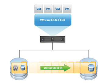
VMware Storage VMotion is a component of VMware vSphere™that provides an intuitive interface for live migration of virtual machine disk files within and across storage arrays with no downtime or disruption in service. Storage VMotion relocates virtual machine disk files from one shared storage location to another shared storage location with zero downtime, continuous service availability and complete transaction integrity. StorageVMotion enables organizations to perform proactive storage migrations, simplify array migrations, improve virtual machine storage performance and free up valuable storage capacity.Storage VMotion is fully integrated with VMware vCenter Server to provide easy migration and monitoring.

How does it work

1. Before moving a virtual machines disk file, Storage VMotion moves the “home directory” of the virtual machine to the new location. The home directory contains meta data about the virtual machine (configuration, swap and log files).

2. After relocating the home directory, Storage VMotion copies the contents of the entire virtual machine storage disk file to the destination storage host, leveraging “changed block tracking” to maintain data integrity during the migration process.

3. Next, the software queries the changed block tracking module to determine what regions of the disk were written to during the first iteration, and then performs a second iteration of copy, where those regions that were changed during the first iteration copy (there can be several more iterations).

4. Once the process is complete, the virtual machine is quickly suspended and resumed so that it can begin using the virtual machine home directory and disk file on the destination datastore location.

5. Before VMware ESX allows the virtual machine to start running again, the final changed regions of the source disk are copied over to the destination and the source home and disks are removed.

What machines can you not Storage vMotion?

1. Virtual machines with snapshots cannot be migrated using Storage vMotion

2. Migration of virtual machines during VMware Tools installation is not supported

3. The host on which the virtual machine is running must have a license that includes Storage vMotion.

4. ESX/ESXi 3.5 hosts must be licensed and configured for vMotion. ESX/ESXi 4.0 and later hosts do not require vMotion configuration in order to perform migration with Storage vMotion.

5. The host on which the virtual machine is running must have access to both the source and target datastores

6. Virtual machine disks in non-persistent mode cannot be migrated

7. Clustered applications or clustered virtual machine configurations do not support Storage vMotion.

8. For vSphere 4.0 and higher, Virtual Disks and Virtual RDM pointer files can be relocated to a destination datastore, and can be converted to thick provisioned or thin provisioned disks during migration as long as the detsination is not an NFS Datastore

9. Physical Mode Pointer files can be relocated to the destination datastore but cannot be converted

vSphere 5 Licensing

This post has been written so I and others can start to understand vSphere licensing

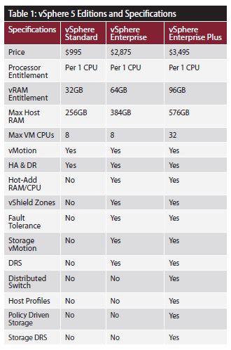
Comparison of vSphere 5 Editions

VMware vSphere 5 licensing

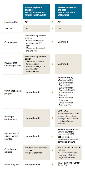
vSphere 5 will be licensed on a per processor basis with a vRAM entitlement. Each vSphere 5 processor license will entitle the purchaser to a specific amount of vRAM, or memory configured to virtual machines. The vRAM entitlement can be pooled across a vSphere environment to enable a true cloud or utility-based IT consumption model. Just like VMware technology offers customers an evolutionary path from the traditional datacenter to a cloud infrastructure, the new vSphere 5 licensing model allows customers to evolve to a cloud-like “pay for consumption” model without disrupting established purchase, deployment, and license management practices and processes. Unlike vSphere 4.x licenses, vSphere 4.x licenses, vSphere 5 licenses do not impose any limits on the number of cores per processors and maximum size of RAM capacity per host

Licensing PDF

http://www.vmware.com/files/pdf/vsphere_pricing.pdf

A diagram showing licesning changes between vSphere 4.x and vSphere 5.x

Should vCenter and the vCenter DB be on the same subnet as the hosts

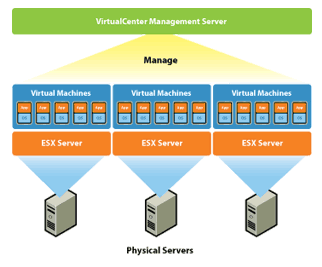
Because vSphere is not a single stand-alone server, application, or isolated computing system, the pieces of the puzzle will require some form of communication between them. There are many possible configuration scenarios depending on the environment in which vSphere is being deployed.

A vCenter Server must be able to communicate with each host and each vSphere client. Furthermore, if a remote database server is utilized rather than a local instance of the database, the required TCP/IP ports for that database installation are also required.

If an instance of vCenter Server is installed on Windows Server 2008, you must either disable the Windows Firewall or make an exception to allow communication between all of the required pieces of the environment.

vCenter Server requires several ports to be open when you select a default installation. Each of these ports will be used for a different portion of the overall communications path. To enable proper communication between each of the components, consult a network engineer to ensure the appropriate ports are open for communication.

Web ports that are required to be open include the following:

Port


Description

80

Required for the purpose of redirecting nonsecure requests to vCenter Server on a secure port

443

The default port used to communicate with vSphere Client and to look for data from vSphere Web Access Client and other VMware Software Development Kit (SDK) applications such as the VI Toolkit. You can change this port, but vSphere Client and any SDK applications must use the vCenter Server name, followed by the nondefault port number

8080

The port used by Web Services HTTP.

8443

The port used by Web Services HTTPS

389

The standard port number used for Lightweight Directory Access Protocol (LDAP) services. This port is used for the Directory Services component of vCenter Server. It must be available to vCenter Server, even if vCenter Server is not part of a Linked Mode Group. You can change from port 389 to any available port ranging from 1025 to 65535. This is the normal LDAP port that the vCenter Server Active Directory Application Mode (ADAM) instance listens on.

636

Used when using vCenter in Linked Mode. This is the Secure Sockets Layer (SSL) port of the local vCenter Server ADAM Instance. It is the preferred port number, but it can also be changed to any available port ranging from 1025 to 65535.

902

Used for multiple tasks. It is used to manage ESX and ESXi hosts and send data to them. vCenter Server also receives a heartbeat at regular intervals from hosts on port 902 over User Datagram Protocol (UDP). This port must not be blocked between vCenter Server and hosts, or between hosts. Port 902 is also used for providing remote console access to virtual machines from vSphere Client.

903

Used in the same fashion as 902: it provides remote console access of virtual machines to vSphere Client. These ports must be open for proper communication to occur between vCenter Server and vSphere Client, as well as from vSphere Client and the ESX and ESXi hosts

vCenter and the vCenter Database

If you want or need to have vCenter and the vCenter Database on separate VLAN’s, you only need to be sure you have enough network bandwidth and speed between them so that the VC performance will not be affected

A host interacts with the vCenter Server through two host management agents: hostd and vpxa. Hostd is started on the host during ESX boot up. It is primarily responsible for bookkeeping of the host-level entities like VMs, datastores, networks, and so on. It is also responsible for implementing the host-level functions of the vSphere Infrastructure API. The vCenter Server dispatches host-related operations to a host over the Web using a SOAP interface. On the host, another agent called vpxa listens to these SOAP requests and dispatches them to hostd using the vCenter Server API. When a host is added to a vCenter Server inventory, vpxa is installed and started on the host. The resource consumption of hostd and vpxa can be monitored using esxtop.
Because vCenter Server communicates with an ESX host through the vSphere Infrastructure API using a SOAP interface, one of the key contributors to the operational latencies is the number of network hops between vCenter Server and the ESX host. If the ESX host is located multiple network hops away from the vCenter Server, the operational latencies may increase significantly. It is therefore recommended that the ESX host resides as few network hops away from the vCenter Server and the DB as possible

VMware Compatibility Guide

VMware Compatibility Guide

The detailed lists show actual vendor devices that are either physically tested or are similar to the devices tested by VMware or VMware partners. VMware provides support only for the devices that are listed in this document

Benchmarking using Performance Tools

Depending on what application you’re trying to model in your VMware test lab, there are a variety of benchmarking tools you can use to stress-test your configuration. VMware provides an extensive benchmarking suite with its VMmark and View Planner offerings.

VMmark incorporates vMotion and Storage vMotion in addition to generating a simulated user workload. View Planner uses Microsoft Office, Adobe Reader and other applications to emulate a typical user workload in a virtual desktop infrastructure, allowing you to measure application delay and user experience on numerous VMs simultaneously.

There are several other load generators available, and with the exception of the SPEC and VMware View Planner benchmarks, you can download them all for free.

File Server Capacity Tool (FSCT): This Microsoft utility drives a load on a traditional CIFS/SMB/SMB2 file server and measures the highest throughput that a server (physical or virtual) can sustain.

Exchange Load Generator 2010 (LoadGen): This Microsoft utility simulates a variety of Exchange email clients at various load levels to help you size your servers before deployment.

Exchange Server Jetstress 2010: This Microsoft utility focuses on the back-end input/output subsystem of the Exchange environment.

Dell DVD Store Database Test Suite: Also part of VMmark, this test suite simulates typical ecommerce site transactions, with built-in load generation.